1989 MITSUBISHI GALANT ignition
[x] Cancel search: ignitionPage 950 of 1273
ACTIVE-ELECTRONIC CONTROL SUSPENSION - Troubleshooting 33B-11
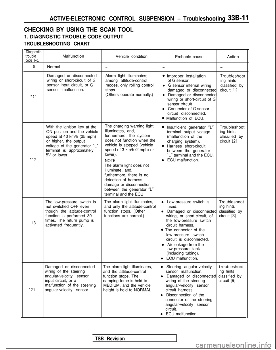
CHECKING BY USING THE SCAN TOOL
1. DIAGNOSTIC TROUBLE CODE OUTPUT
TROUBLESHOOTING CHART
DiagnostictroubleMalfunctionVehicle conditioncode No.Probable causeAction
0Normal---
Damaged or disconnected
Alarm light illuminates;0 Improper installation Troubleshoof
wiring or short-circuit of Gamong attitude-control of G sensor.
sensor input circuit, or Ging hints
modes, only rolling control
sensor malfunction. l
G sensor internal wiring
classified by
stops. damaged or disconnected. circuit
[I]
“11(Others operate normally.)l Damaged or disconnected
wiring or short-circuit of
G
sensor circurt.
l Connector of
G sensor
circuit disconnected.
0 Malfunction of ECU.
W
ith the ignition key at the
The charging warning light
ON position and the vehicle illuminates, and,
0 Insufficient generator “L”Troubleshoot
speed at 40 km/h (25 mph) furthermore, the system terminal output voltage
ing hints
or higher, the output does not function when the (malfunction of the
classified by
charging system). circuit
[2]
voltage of the generator ‘I”vehicle is stopped (vehicle0 Harness short-circuit
terminal is approximately speed of 3 km/h (2 mph) or
5V or lower
lower). between the generator“L” terminal and the ECU.“12
NOTEl ECU malfunction.
The alarm light does not illuminate, and,
furthermore, there is no
detection of harness
damage or disconnection
between the generator “L”
terminal and the ECU.
The low-pressure switch is The alarm light illuminates,
l Low-pressure switch is Troubleshoot
not switched OFF even and only the attitude-control
fused.
though the attitude-control ing hints
function stops. (Other l Damaged or disconnected classified by
function is performed 30 functions are normal.) circuit
131
13times. The return pump is wiring, or short-circuit, of
the low-pressure switch
activated frequently. circuit harness.
0 The connector of the
low-pressure switch
circuit is disconnected.
l Air leakage from the low-pressure tank
(including tubing).
l ECU malfunction.
“21
Damaged or disconnected The alarm light illuminates,l Steering angular-velocity Troubleshoot-
wiring of the steering and the attitude-control sensor malfunction.
angular-velocity sensor ing hints
function stops. The
input circuit, or a l Damaged or disconnected classified by
damping force is held to wiring of the steeringcircuit
191malfunction of the steenng
MEDIUM, and the vehicle
angular-velocity sensor. angular-velocity sensor
height is held to NORMAL circuit harness.
l Disconnection of the connector of the steering
angular-velocity sensor
circuit.
l ECU malfunction.
TSB Revision
Page 956 of 1273
![MITSUBISHI GALANT 1989 Service Repair Manual ACTIVE-ELECTRONIC CONTROL SUSPENSION - Troubleshooting 33B-17
CHECKING ACCORDING TO CHARTS CLASSIFIED BY THE MALFUNCTION SYMPTOM
[A] DIAGNOSTIC TROUBLE CODE NO.54
No
Yes
b Excessive vehicle-height ad-](/manual-img/19/57312/w960_57312-955.png "MITSUBISHI GALANT 1989 Service Repair Manual ACTIVE-ELECTRONIC CONTROL SUSPENSION - Troubleshooting 33B-17
CHECKING ACCORDING TO CHARTS CLASSIFIED BY THE MALFUNCTION SYMPTOM
[A] DIAGNOSTIC TROUBLE CODE NO.54
No
Yes
b Excessive vehicle-height ad-")
ACTIVE-ELECTRONIC CONTROL SUSPENSION - Troubleshooting 33B-17
CHECKING ACCORDING TO CHARTS CLASSIFIED BY THE MALFUNCTION SYMPTOM
[A] DIAGNOSTIC TROUBLE CODE NO.54
No
Yes
b Excessive vehicle-height ad-justment
(overload) overload). time (due to -Unload the vehicle and turn* the ignition key to OFF; then
restart the engine and check
whether or not the system
functions normally.
Is the installation position of Nothe height sensor correct?
Yes Improper setting of the heightc sensor, or malfunction of the
height sensor. l Correct the installationcposition of the height sen-
sor, or adjust the vehicle
-height sensor rod.
l Check the height sensor. Refer to troubleshooting
hints [IO] and
[ll]classified by circuit.
Are the front strut and rear
NoMalfunction of the rolling
shock absorber unit air spr-* diaphragm.
Repair the rolling diaphragm,
or replace the shock absorber
ings in normal condition?Lunit.
(become folded)
Yes
Is the sound of operation
NoThe solenoid valves remain
heard from each solenoid closed, or there is air leakage
valve necessary for th
e
’ due to a malfunction of the
vehicle-height adjustment? valve seat.
Yes
Is the air pressure in the
vehicle-height adjustment
Nopressure line 950 kPa (135
psi) or higher?
I
Yes Damaged or disconnected
wiring of the high-pressure
switch, or incorrect vehicle
-height adjustment pressureline.
l Check the high-pressure switch circuit.
* Refer to troubleshooting hint [5] classified by circuit.
l Correct the clogging pro-
blem, or replace the air
tube.
Control unit malfunction.
[B] DIAGNOSTIC TROUBLE CODE NO.55
- No
Does the compressor func-
tion normally?
Yes Replace the control unit.c l Power is not supplied to
the compressor.Refer to troubleshooting
hint
[18] classified by cir-
cuit.
0 Improper compressor com- pression.
Is the air pressure in the
Novehicle-height adjustment
pressure line 760 kPa (108psi) or lower? High-pressure
switch
isRefer to troubleshooting hint
shorted____* [5] classified by circuit.
Yes Air leakage.
TSB RevisionI
Page 957 of 1273
33B-18 ACTIVE-ELECTRONIC CONTROL SUSPENSION - Troubleshooting
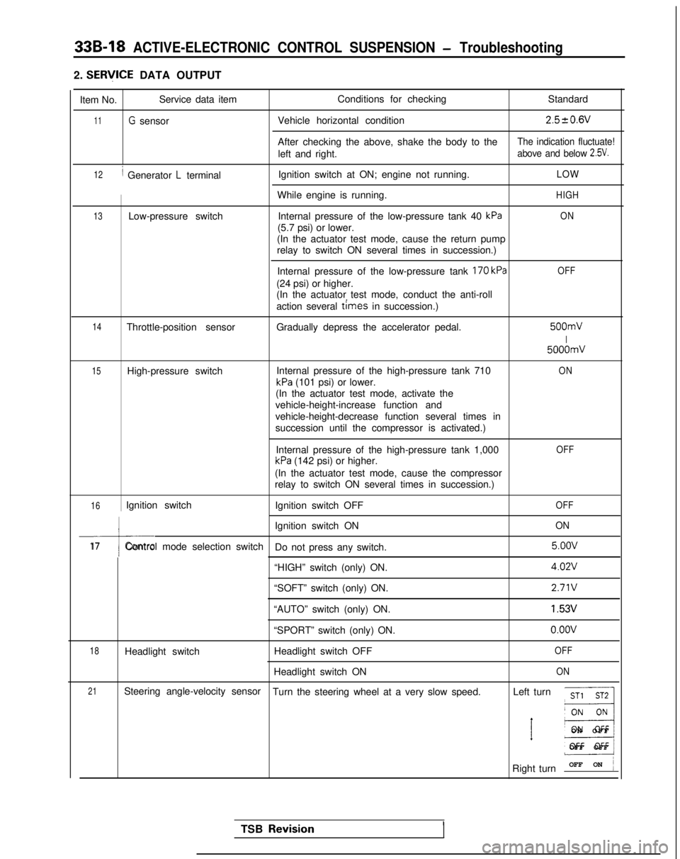
2. SERlflCE DATA OUTPUT
Item No. Service data item
Conditions for checking
Standard
11G sensorVehicle horizontal condition2.520.6V
After checking the above, shake the body to theThe indication fluctuate!
left and right.above and below 2.5V.
12/ Generator L terminalIgnition switch at ON; engine not running.LOW
While engine is running.HIGH
13Low-pressure switch
Internal pressure of the low-pressure tank 40 kPaON
(5.7 psi) or lower.
(In the actuator test mode, cause the return pump
relay to switch ON several times in succession.)
Internal pressure of the low-pressure tank
170 kPa
(24 psi) or higher.
(In the actuator test mode, conduct the anti-roll
action several
times in succession.)
OFF
14Throttle-position sensor Gradually depress the accelerator pedal. 500mV
I
5000mV
15High-pressure switch
Internal pressure of the high-pressure tank 710ON
kPa (101 psi) or lower.
(In the actuator test mode, activate the
vehicle-height-increase function and
vehicle-height-decrease function several times in
succession until the compressor is activated.)
Internal pressure of the high-pressure tank 1,000
kPa (142 psi) or higher.
OFF
(In the actuator test mode, cause the compressor
relay to switch ON several times in succession.)
16Ignition switch Ignition switch OFFOFF
I
Ignition switch ONON
17Control mode selection switch
Do not press any switch. 5.oov
“HIGH” switch (only) ON.
4.02V
“SOFT” switch (only) ON.2.71V
“AUTO” switch (only) ON.1.53V
“SPORT” switch (only) ON.o.oov
18Headlight switch Headlight switch OFFOFF
Headlight switch ONON
21Steering angle-velocity sensor
Turn the steering wheel at a very slow speed. Left turnST1 ST2
__I
’ E3
ON OF
F
OFF OFF
Right turn OFF ON
j
TSB Revisio.nI
Page 964 of 1273
ACTIVE-ELECTRONIC CONTROL SUSPENSION - Troubleshooting 33B-25
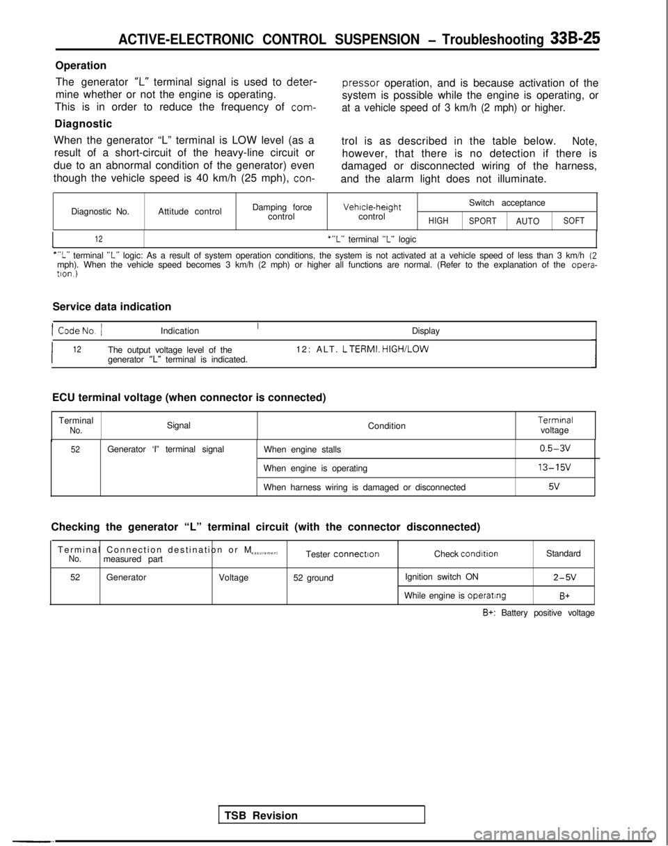
OperationThe generator
‘I-” terminal signal is used to deter-
pressor
operation, and is because activation of the
mine whether or not the engine is operating.
This is in order to reduce the frequency of
com-
system is possible while the engine is operating, or
at a vehicle speed of 3 km/h (2 mph) or higher.
Diagnostic
When the generator “L” terminal is LOW level (as a result of a short-circuit of the heavy-line circuit or
due to an abnormal condition of the generator) even
though the vehicle speed is 40 km/h (25 mph),
con-
trol is as described in the table below.Note,
however, that there is no detection if there is
damaged or disconnected wiring of the harness,
and the alarm light does not illuminate.
Diagnostic No. Attitude control Damping force
control Vehrcle-height
control
HIGH
Switch acceptance
SPORTAUTOSOFT
I12‘“L” terminal “L” logic
““L” terminal “L” logic: As a result of system operation conditions, the system is not ac\
tivated at a vehicle speed of less than 3 km/h (2mph). When the vehicle speed becomes 3 km/h (2 mph) or higher all fun\
ctions are normal. (Refer to the explanation of the opera-
tron.)
Service data indication
1 CodeNo. /Indication Display
I12The output voltage level of the12: ALT. LTERMI.
HIGH/LOW
generator “L” terminal is indicated.
TSB Revision
ECU terminal voltage (when connector is connected)
Terminal
No.Signal Condition Termrnal
voltage
52Generator ‘I” terminal signal When engine stalls
When engine is operating
When harness wiring is damaged or disconnected0.5-3v
13-15v
5v
Checking the generator “L” terminal circuit (with the connector d\
isconnected)
Terminal Connection destination or
M
easurement
No.measured part Tester connectronCheck condrtion
Standard
52 Generator
Voltage52 ground Ignition switch ON
2-5V
While engine is operatingB+
B+: Battery positive voltage
Page 972 of 1273
ACTIVE-ELECTRONIC CONTROL SUSPENSION - Troubleshooting 33B-33
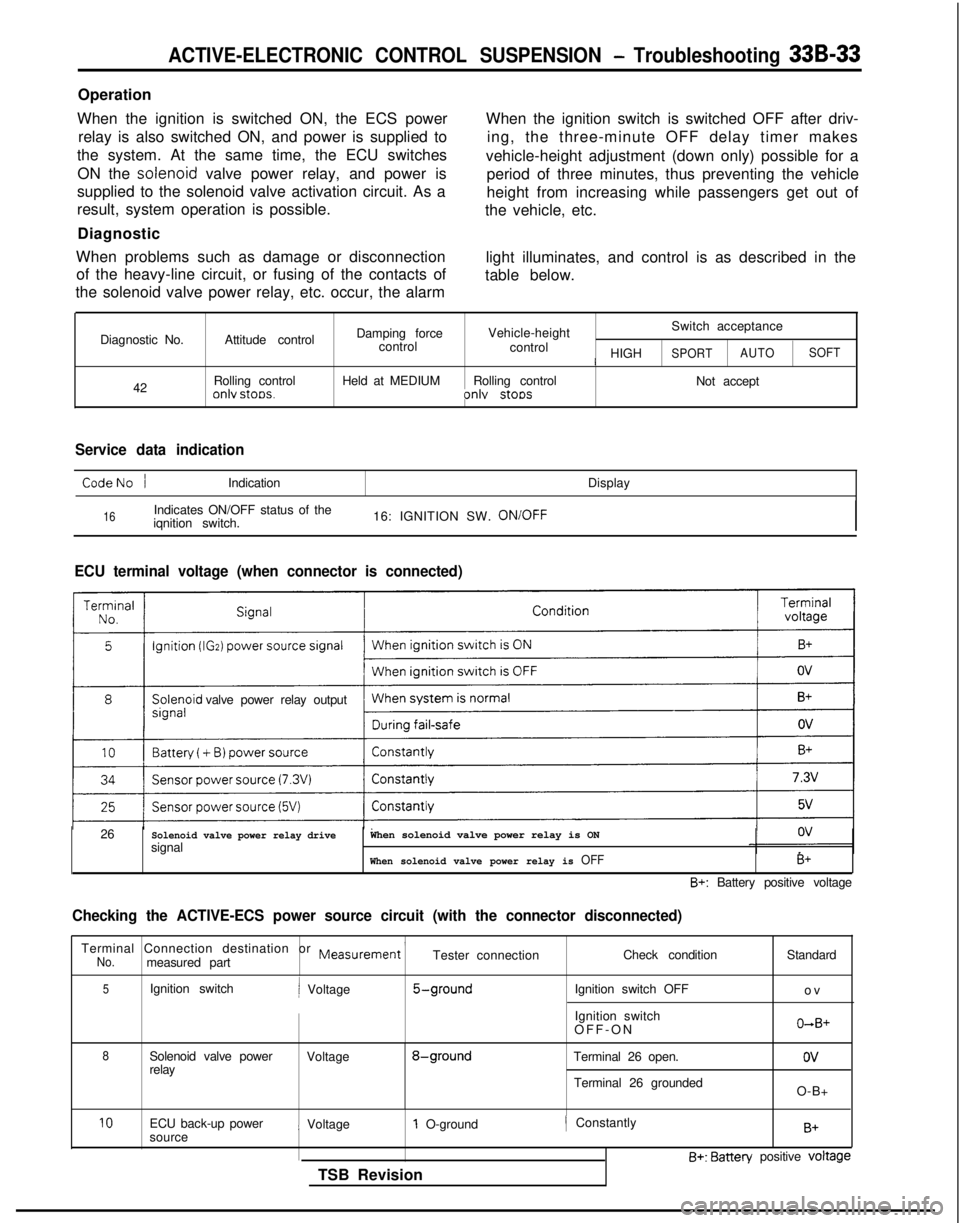
Operation
When the ignition is switched ON, the ECS power relay is also switched ON, and power is supplied to
the system. At the same time, the ECU switches
ON the solenoid
valve power relay, and power is
supplied to the solenoid valve activation circuit. As a
result, system operation is possible.
Diagnostic
When problems such as damage or disconnection of the heavy-line circuit, or fusing of the contacts of
the solenoid valve power relay, etc. occur, the alarm When the ignition switch is switched OFF after driv-
ing, the three-minute OFF delay timer makes
vehicle-height adjustment (down only) possible for a period of three minutes, thus preventing the vehicle
height from increasing while passengers get out of
the vehicle, etc.
light illuminates, and control is as described in the
table below.
Diagnostic No. 42 Attitude control
Rolling control
onlv stoos.
Damping force
Vehicle-height Switch acceptance
control control
/ HIGHSPORTAUTOSOFT
Held at MEDIUM
Rolling control
Not acceptonlv stoos
Service data indication
CodeNo /Indication Display
16Indicates ON/OFF status of the
iqnition switch. 16: IGNITION SW. ON/OFF
ECU terminal voltage (when connector is connected)
valve power relay output
26
Solenoid valve power relay drivesignalWhen solenoid valve power relay is ON
When solenoid valve power relay is OFFB+
B+: Battery positive voltage
Checking the ACTIVE-ECS power source circuit (with the connector discon\
nected)
Terminal Connection destination or Measurement ’No.measured part Tester connection
Check condition
5Ignition switchi Voltage5-groundIgnition switch OFF
Ignition switch
OFF-O
N
8Solenoid valve power
Voltage8-groundTerminal 26 open.
relay
Terminal 26 groundedStandard
o
v
O+B+
ov
O-B+
10ECU back-up power
sourcei Voltage1 O-ground
TSB Revision/ ConstantlyB+
B+: Batten/ positive voltage
Page 974 of 1273
ACTIVE-ELECTRONIC CONTROL SUSPENSION - Troubleshooting 33B-35
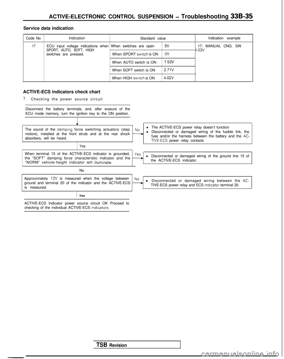
Service data indication
Code No Indication
Standard value
17ECU input voltage indications when When switches are openSPORT, AUTO, SOFT, HIGH5V
switches are pressed.When SPORT switch
is ONOV
When AUTO switch is ON1.53v
When SOFT switch is ON 2.71V
When HIGH swrtch
is ON 4.02V
ACTIVE-ECS indicators check chart
1.Checking the power source circuit
Disconnect the battery terminals, and, after erasure of the
ECU mode memory, turn the ignition key to the ON position.
1
Indication example
17: MANUAL CNG. SW
4.03v
The sound of the damplng force switching actuators (steplNoThe ACTIVE-ECS power relay doesn’t function
motors), installed at the front struts and at the rear shock
--+l Disconnected or damaged wiring of the fusible link, the
absorbers, will be heard. fuse and/or the harness between the battery and the AC-TIVE-ECS power relay contacts
Yes
When terminal 15 of the ACTIVE-ECS indicator is grounded,yes
the “SOFT” damping force characteristic indicator and the -lDisconnected or damaged wiring of the ground line 15 of
“NORM” vehicle-height indicator will
illuminate.the ACTIVE-ECS indicator.
No
Approximately
12V is measured when the voltage betweenNo
ground and terminal 20 of the indicator and the ACTIVE-ECS --+l Disconnected or damaged wiring between the AC-
is measured. TIVE-ECS power relay and ECS Indicator
terminal 20.
I Yes
TSB Revision
-. ACTIVE-ECS Indicator power source circuit OK Proceed to
checking of the individual ACTIVE-ECS
lndlcators
Page 977 of 1273
![MITSUBISHI GALANT 1989 Service Repair Manual 33B-38 ACTIVE-ELECTRONIC CONTROL SUSPENSION - Troubleshooting
[8] HEADLIGHT SWITCH CIRCUIT
Battery1I
4Ignition
Tswitch (ACC)
c-43 l-
(From 1991 models)
(From 1990 models) A-01X
Head-
light
ECU
-L
II;](/manual-img/19/57312/w960_57312-976.png "MITSUBISHI GALANT 1989 Service Repair Manual 33B-38 ACTIVE-ELECTRONIC CONTROL SUSPENSION - Troubleshooting
[8] HEADLIGHT SWITCH CIRCUIT
Battery1I
4Ignition
Tswitch (ACC)
c-43 l-
(From 1991 models)
(From 1990 models) A-01X
Head-
light
ECU
-L
II;")
33B-38 ACTIVE-ELECTRONIC CONTROL SUSPENSION - Troubleshooting
[8] HEADLIGHT SWITCH CIRCUIT
Battery1I
4Ignition
Tswitch (ACC)
c-43 l-
(From 1991 models)
(From 1990 models) A-01X
Head-
light
ECU
-L
II;
50 >
c
;-ii -I
Kin.>r(
3
OA
/\7'6
1
I
To column switch TL
‘89F-l 6
IITo meter (upper beamindicator light)
8A
headlight
pjjimmj
C-23 (From 1990 models)
12*0642
NOTE* mark and chain line indicate 1991, 1992, 1993 models.
TSB Revision
Page 990 of 1273
ACTIVE-ELECTRONIC CONTROL SUSPENSION - Troubleshooting 33B-51
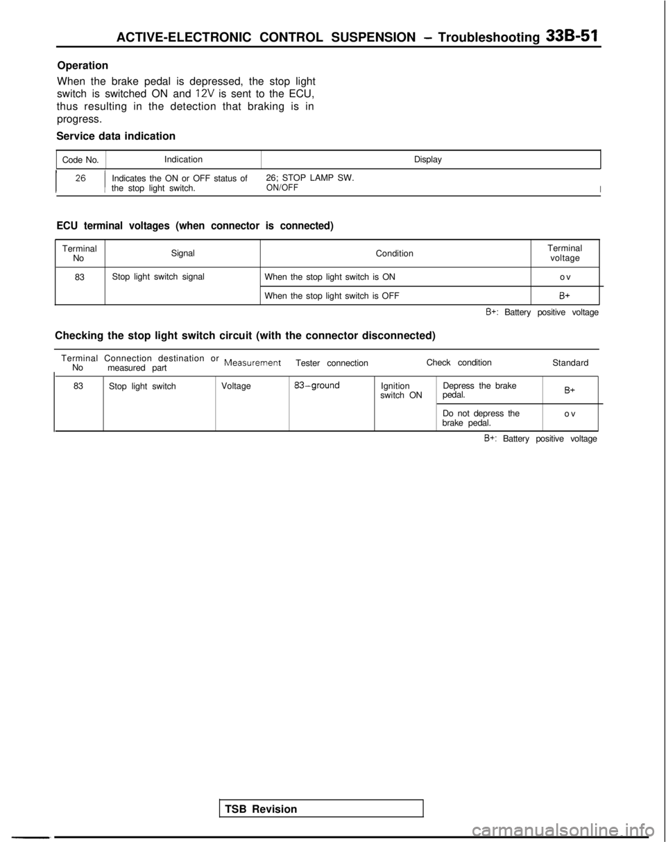
Operation
When the brake pedal is depressed, the stop light
switch is switched ON and
1% is sent to the ECU,
thus resulting in the detection that braking is in progress.
Service data indication
Code No. Indication
Display
I 26 I
Indicates the ON or OFF status of26; STOP LAMP SW.
the stop light switch.ON/OFFI
ECU terminal voltages (when connector is connected)
Terminal Signal ConditionTerminal
No voltage
83 Stop light switch signal
When the stop light switch is ON o
v
When the stop light switch is OFF
B+
B+: Battery positive voltage
Checking the stop light switch circuit (with the connector disconnected\
) Terminal Connection destination or
MeasurementNo measured part Tester connection
Check condition
Standard
83 Stop light switch Voltage
83-groundIgnitionDepress the brake
switch ON pedal.B+
Do not depress the
o
v
brake pedal.
B+: Battery positive voltage
TSB Revision
-,