1989 MITSUBISHI GALANT fuel cap
[x] Cancel search: fuel capPage 147 of 1273
FUEL SYSTEM
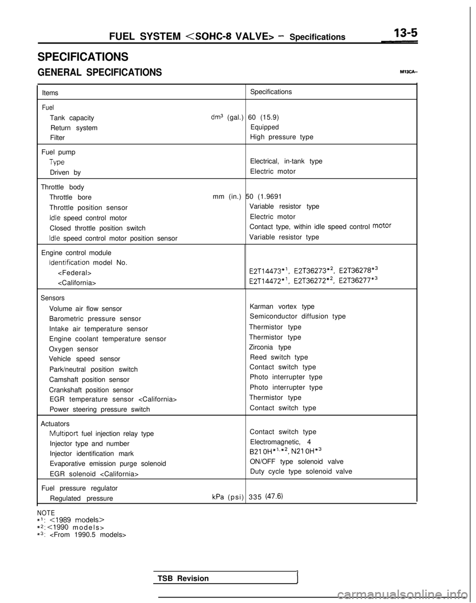
SPECIFICATIONS
GENERAL SPECIFICATIONS
Items
Fuel
Tank capacity
Return system
Filter
Fuel pump
Type
Driven by
Throttle body Throttle bore
Throttle position sensor
Idle speed control motor
Closed throttle position switch
Idle speed control motor position sensor
Engine control module Identification
model No.
Sensors
Volume air flow sensor
Barometric pressure sensor
Intake air temperature sensor
Engine coolant temperature sensor
Oxygen sensor
Vehicle speed sensor
Park/neutral position switch
Camshaft position sensor
Crankshaft position sensor EGR temperature sensor
Power steering pressure switch
Actuators
Multiport fuel injection relay type
Injector type and number
Injector identification mark
Evaporative emission purge solenoid
EGR solenoid
Fuel pressure regulator Regulated pressure
NOTE*I:
*3:
dm3 (gal.) 60 (15.9)
Equipped
High pressure type
Electrical, in-tank type
Electric motor
mm (in.) 50 (1.9691 Variable resistor type
Electric motor
Contact type, within idle speed control motor
Variable resistor type E2T14473*‘,
E2T36273*2, E2T36278*3
E2T14472”. E2T36272*2, E2T36277*3
Karman vortex type
Semiconductor diffusion type
Thermistor type
Thermistor type
Zirconia type Reed switch type
Contact switch type
Photo interrupter type
Photo interrupter type
Thermistor type
Contact switch type
Contact switch typeElectromagnetic, 4
B21 OH*‘,*2,
N21 OH*3
ON/OFF type solenoid valve
Duty cycle type solenoid valve
kPa (psi) 335 (47.6)
TSB RevisionI
Page 151 of 1273
FUEL SYSTEM
13-9
r
I Connector
6FU1216
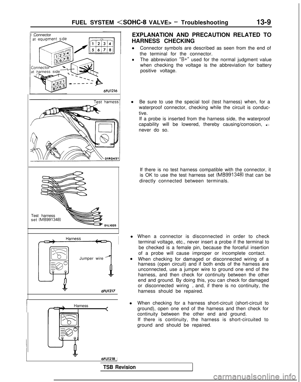
EXPLANATION AND PRECAUTION RELATED TO
HARNESS CHECKING
l Connector symbols are described as seen from the end of
the terminal for the connector.
lThe abbreviation “B+”
used for the normal judgment value
when checking the voltage is the abbreviation for battery positive voltage.
Test harness
set (MB991348)
Jumper wire
&6FU1217
Harness <
LQ
Q,
6FUlZlBj
l
Be sure to use the special tool (test harness) when, for a
waterproof connector, checking while the circuit is conduc-
tive. If a probe is inserted from the harness side, the waterproof
capability will be lowered, thereby causing/corrosion, SO
never do so.
If there is no test harness compatible with the connector, it
is OK to use the test harness set (MB991348)
that can be
directly connected between terminals.
l When a connector is disconnected in order to check terminal voltage, etc., never insert a probe if the terminal to
be checked is a female pin, because the forceful insertion
of a probe will cause improper or incomplete contact.
l When checking for damaged or disconnected wiring of a
harness (open circuit) and if both ends of the harness are
unconnected, use a jumper wire to ground one end of the
harness, and then check for continuity between the other
end and ground. By doing this, you can check for damaged
or disconnected wiring
., and, if there is no continuity, the
harness should be repaired.
l When checking for a harness short-circuit (short-circuit to
ground), open one end of the harness and then check for
continuity between the other end and ground.
If there is continuity, the harness is short-circuited to
ground and should be repaired.
TSB Revision
Page 174 of 1273
13-32
FUEL SYSTEM
FUEL TANK AND FUEL LINEMlBEAAA
Symptom Probable cause Remedy
Engtne malfunctions
Bent or kinked fuel pipe or hose Repair or replace3ue to insufficient fuel
SUPPlYClogged fuel pipe or hoseClean or replace
Clogged fuel filter or in-tank fuel filter Replace
Water in fuel filter Replace the fuel filter or clean the fuel tank
and fuel line
Dirty or rusted fuel tank interior Malfunctioning fuel pump
(Clogged filter in the pump) Clean or replace
Replace
Evaporative emission Mispiping of vapor line
Correct
control system malfunc-
tions (When fuel tank Disconnect vapor line piping joint Correct
filler tube cap is re- moved, pressure releas-
Folded, bent, cracked or clogged vapor line Replace
ng noise is heard) Faulty fuel tank filler tube cap
Malfunctioning fuel tank pressure control
valve Replace
Replace
LL
m ~~ : Paper clip-
F l!;“I /yFp- -
izd--_7-01
A0086SERVICE ADJUSTMENT PROCEDURES
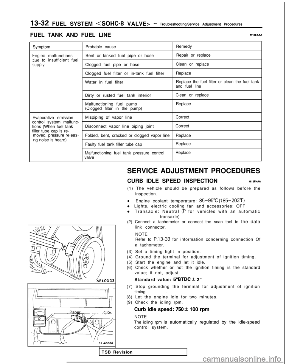
CURB IDLE SPEED INSPECTION
MlBFHAFt
(1) The vehicle should be prepared as follows before the inspection.
lEngine coolant temperature: 85-95°C (185-203°F)
l Lights, electric cooling fan and accessories: OFF
l Transaxle: Neutral
(P for vehicles with an automatic
transaxle)
(2) Connect a tachometer or connect the scan tool to the data
link connector.
NOTE
Refer to
P.13-33 for information concerning connection Of
a tachometer.
(3) Set a timing light in position.
(4) Ground the terminal for adjustment of ignition timing.
(5) Start the engine and let it idle.
(6) Check whether or not the ignition timing is the standard
value; if not, adjust.
Standard value:
5”BTDC + 2”
(7) Stop grounding the terminal for adjustment of ignition timing. .
(8) Let the engine idle for two minutes.
(9) Check the idling rpm.
Curb idle speed:
7502 100 rpm
NOTE
The idling rpm is automatically regulated by the idle-speed control system.
1
TSB Revision
Page 251 of 1273
FUEL SYSTEM
FUEL TANK MlSGA-
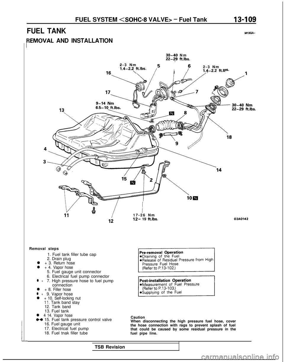
{EMOVAL AND INSTALLATION
r
30-40 N
m
22-?9
ft.lbs.
2-3 Nm
1.4-2.2,ft.lbs.IP
2-3 N
m
1.4-2.2 f-Lit
6.5-10
ft.lbs.
!I17-26 N
m
12- 19
ft.lbs.
Removal steps 1. Fuel tank filler tube cap
2. Drain plug
l + 3. Return hosel + 4. Vapor hose5. Fuel gauge unit connector
6. Electrical fuel pump connector
l +7. High pressure hose to fuel pump connection
l + 8. Filler hosel +9. Vapor hosel + 10. Self-locking nut11, Tank band stay12. Tank band13. Fuel tankl 4 14. Vapor hosee+ 15. Fuel tank pressure control valve
16. Fuel gauge unit
17. Electrical fuel pump
18. Fuel tnak filler tube
i8
03A0142
Caution
When disconnecting the high pressure fuel hose, cover
the hose connection with rags to prevent splash of fuel that could be caused by some residual pressure in the
fuel pipe line.
TSB Revision
Page 252 of 1273
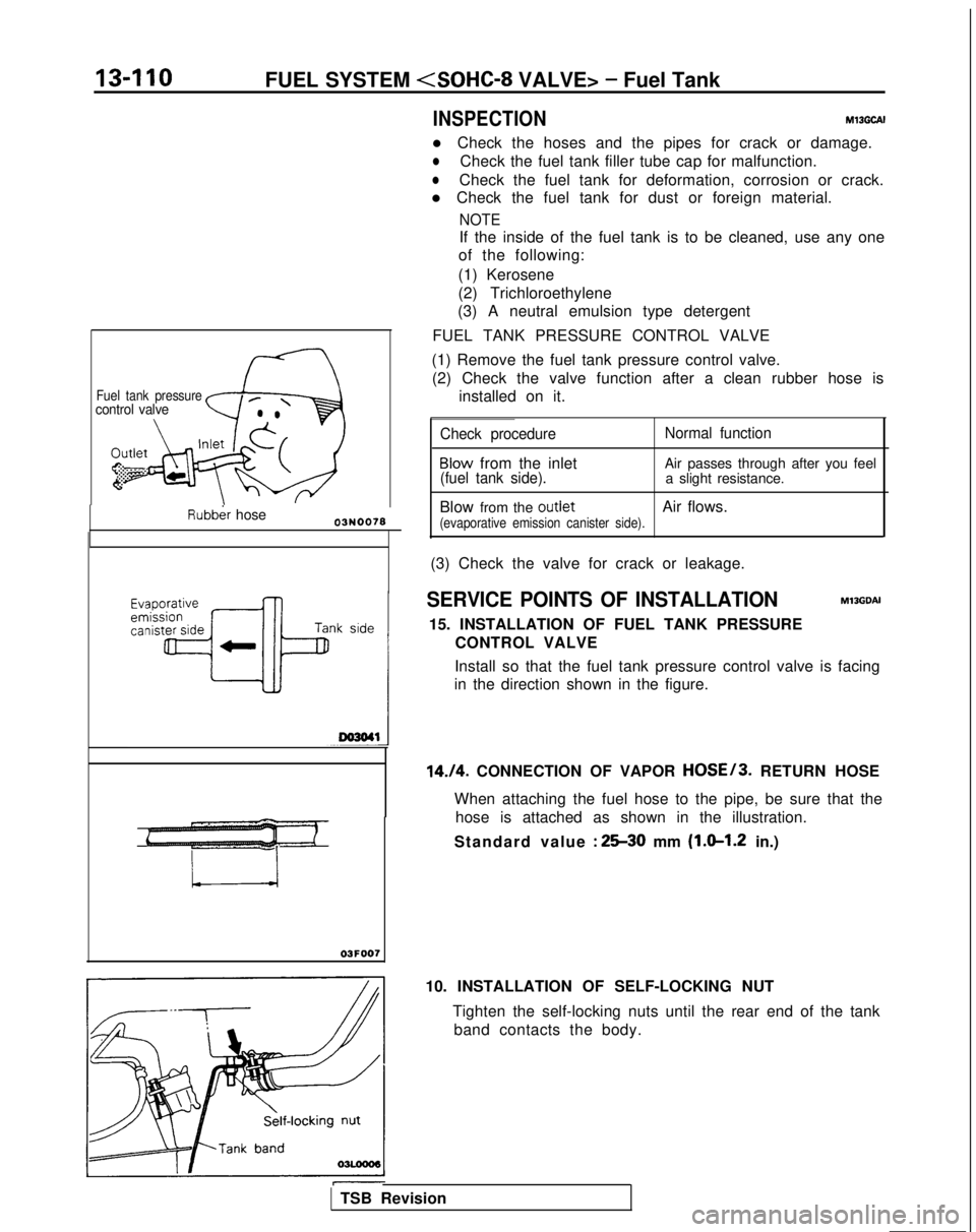
Fuel tank pressurecontrol valve
Rubber hose
n-110FUEL SYSTEM
INSPECTIONMl3GCAI
l Check the hoses and the pipes for crack or damage.
lCheck the fuel tank filler tube cap for malfunction.
lCheck the fuel tank for deformation, corrosion or crack.
l Check the fuel tank for dust or foreign material.
NOTE
If the inside of the fuel tank is to be cleaned, use any one
of the following:
(1) Kerosene
(2) Trichloroethylene
(3) A neutral emulsion type detergent
FUEL TANK PRESSURE CONTROL VALVE
(1) Remove the fuel tank pressure control valve. (2) Check the valve function after a clean rubber hose is installed on it.
Check procedure Normal function
Blow from the inlet
Air passes through after you feel(fuel tank side).a slight resistance.
Blow from the
outletAir flows.(evaporative emission canister side).
(3) Check the valve for crack or leakage.
SERVICE POINTS OF INSTALLATIONM13GDAI
15. INSTALLATION OF FUEL TANK PRESSURE CONTROL VALVE
Install so that the fuel tank pressure control valve is facing
in the direction shown in the figure.
14./4. CONNECTION OF VAPOR HOSE/3. RETURN HOSE
When attaching the fuel hose to the pipe, be sure that the hose is attached as shown in the illustration.
Standard value
: 2530 mm (l.sl.2 in.)
03F007
10. INSTALLATION OF SELF-LOCKING NUT
Tighten the self-locking nuts until the rear end of the tankband contacts the body.
TSB Revision
Page 253 of 1273
FUEL SYSTEM
03R0297
Vapor hose
mmin.)Fillerhose
i2.l
B
3FOO7
A
1
Flare nut
Skure side
03Yo43
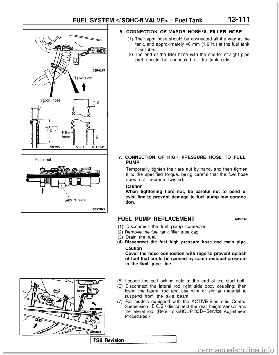
9. CONNECTION OF VAPOR HOSE/8. FILLER HOSE
(1) The vapor hose should be connected all the way at the tank, and approximately 40 mm (1.6 in.) at the fuel tank
filler tube.
(2) The end of the filler hose with the shorter straight pipe
part should be connected at the tank side.
7. CONNECTION OF HIGH PRESSURE HOSE TO FUEL PUMP
Temporarily tighten the flare nut by hand, and then tightenit to the specified torque, being careful that the fuel hose
does not become twisted.
Caution
When tightening flare nut, be careful not to bend or
twist line to prevent damage to fuel pump low connec-
tion.
FUEL PUMP REPLACEMENT
(1) Disconnect the fuel pump connector.
(2) Remove the fuel tank filler tube cap.
(3) Drain the fuel. MllGFAC
(4)
Disconnect the fuel high pressure hose and main pipe.
Caution
Cover the hose connection with rags to prevent splash
of fuel that could be caused by some residual pressure in the
fuel. pipe line.
(5) Loosen the self-locking nuts to the end of the stud bolt.
(6) Disconnect the lateral rod right side body coupling; then lower the lateral rod and use wire or similar material to
suspend from the axle beam.
(7) For models equipped with the ACTIVE-Electronic Control Suspension
(E.C.S.) disconnect the rear height sensor and
the lateral rod. (Refer to GROUP
33B-Service Adjustment
Procedures.)
Page 260 of 1273
13418FUEL SYSTEM (SOHC-16 VALVE> - Specifications
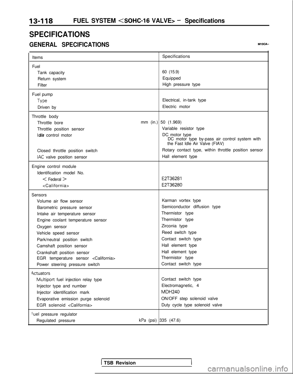
SPECIFICATIONS
GENERAL SPECIFICATIONSMISCA-
Items
Fuel
Tank capacityReturn system
Filter
Fuel pump Type
Driven by
Throttle body Throttle bore
Throttle position sensor Idle air control motor
Closed throttle position switch
IAC valve position sensor
Engine control module Identification model No.
< Federal >
Sensors
Volume air flow sensorBarometric pressure sensor
Intake air temperature sensor
Engine coolant temperature sensor
Oxygen sensor
Vehicle speed sensor
Park/neutral position switch
Camshaft position sensor
Crankshaft position sensor EGR temperature sensor
Power steering pressure switch
Cvctuators
Multiport fuel injection relay type
Injector type and number
Injector identification mark
Evaporative emission purge solenoid
EGR solenoid
pressure regulator
Regulated pressure Specifications
60 (15.9)
Equipped
High pressure type
Electrical, in-tank type
Electric motor
mm (in.) 50 (1.969) Variable resistor typeDC motor type DC motor type by-pass air control system with
the Fast Idle Air Valve (FIAV)
Rotary contact type, within throttle position sensor
Hall element type
E2T36281 E2T36280
Karman vortex type
Semiconductor diffusion type
Thermistor type
Thermistor type Zirconia type
Reed switch type
Contact switch type Hall element type
Hall element type
Thermistor type
Contact switch type
Contact switch type
Electromagnetic, 4 MDH240
ON/OFF step solenoid valve Duty cycle type solenoid valve
kPa (psi) 335 (47.6)
1 TSB Revision
Page 275 of 1273

FUEL SYSTEM
FUEL TANK AND FUEL LINEMIBEAAB
Symptom
Probable cause Remedy
Engine malfunctions
due to insufficient
fuel supply Bent or kinked fuel pipe or hose
Clogged fuel pipe or hose
Clogged fuel filter or in-tank fuel filter
Water in fuel filter Repair or replace
Clean or replace
Replace
Replace the fuel filter or clean the
fuel tank and fuel line
Dirty or rusted fuel tank interior
Clean or replace
Malfunctioning fuel pump
(Clogged filter in the pump)Replace
Evaporative emission
control system
malfunctions
[When fuel tank filler
tube cap is removed,
pressure releasingnoise is heard) Mispiping of vapor line
Disconnected vapor line piping joint
Folded, bent, cracked or clogged vapor line
Faulty fuel tank filler tube cap
Malfunctioning fuel tank pressure control valve Correct
Correct
Replace
Replace
Replace
SERVICE ADJUSTMENT
PROCEDURES
CURB IDLE SPEED INSPECTIONhll3MAE
(1) The vehicle should be prepared as follows before th
e
inspection.
lEngine coolant temperature: 85-95°C (185-203°F)
l Lights, electric cooling fan and accessories: OFF
l Transaxle: Neutral (P for vehicles with an automatic
transaxle)
(2) Connect a tachometer.
NOTE
Refer to
P.13-134 for information concerning connection Of
a tachometer.
(3) Set a timing light in position.
(4) Ground the terminal for adjustment of ignition timing.
(5) Start the engine and let it idle.
(6) Check whether or not the ignition timing is the standard
value; if not, adjust.
Standard value:
5”BTDC f 2”
(7) Stop grounding the terminal for adjustment of ignition timing.
(8) Let the engine idle for two minutes.
(9) Check the idling rpm.
Curb idle speed: 700
31100 rpm
NOTE
The idling rpm is automatically regulated by the idle aircontrol system.
(lO)lf not within the standard value range, refer to the CHECK
CHART CLASSIFIED BY PROBLEM SYMPTOMS and check
the
MFI component,
TS6 Revision1