1989 FORD FIESTA sensor
[x] Cancel search: sensorPage 147 of 296
7 Fuel pump/fuel pressure-
checking
3
Note: Refer to the warning note in Section 1
before proceeding.
Fuel pump operation check
1 Switch on the ignition, and listen for the fuel
pump (the sound of an electric motor running,
audible from beneath the rear seats).
Assuming there is sufficient fuel in the tank,
the pump should start and run for
approximately one or two seconds, then stop,
each time the ignition is switched on. Note:If
the pump runs continuously all the time the
ignition is switched on, the electronic control
system is running in the backup (or “limp-
home”) mode referred to by Ford as “Limited
Operation Strategy” (LOS). This almost
certainly indicates a fault in the EEC IV module
itself, and the vehicle should therefore be
taken to a Ford dealer for a full test of the
complete system, using the correct diagnostic
equipment; do not waste time or risk
damaging the components by trying to test
the system without such facilities.
2 Listen for fuel return noises from the fuel
pressure regulator. It should be possible to
feel the fuel pulsing in the regulator and in the
feed hose from the fuel filter.
3 If the pump does not run at all, check the
fuse, relay and wiring (see Chapter 12). Check
also that the fuel cut-off switch has not been
activated and if so, reset it.
Fuel pressure check
4 A fuel pressure gauge will be required for
this check and should be connected in the
fuel line between the fuel filter and the fuel rail,
in accordance with the gauge maker’s
instructions. On Zetec engines, a pressure
gauge equipped with an adapter to suit the
Schrader-type valve on the fuel rail pressure
test/release fitting (identifiable by its blue
plastic cap, and located on the union of the
fuel feed line and the fuel rail) will be required.
If the Ford special tool 29-033 is available, the
tool can be attached to the valve, and a
conventional-type pressure gauge attached to
the tool.
5 If using the service tool, ensure that its tap
is turned fully anti-clockwise, then attach it to
the valve. Connect the pressure gauge to the
service tool. If using a fuel pressure gauge
with its own adapter, connect it in accordance
with its maker’s instructions.
6 Start the engine and allow it to idle. Note
the gauge reading as soon as the pressure
stabilises, and compare it with the regulated
fuel pressure figures listed in the
Specifications .
a) If the pressure is high, check for a
restricted fuel return line. If the line is
clear, renew the fuel pressure regulator.
b) If the pressure is low, pinch the fuel return
line. If the pressure now goes up, renew the fuel pressure regulator. If the pressure
does not increase, check the fuel feed
line, the fuel pump and the fuel filter.
7 Detach the vacuum hose from the fuel
pressure regulator; the pressure shown on the
gauge should increase. Note the increase in
pressure, and compare it with that listed in the
Specifications . If the pressure increase is not
as specified, check the vacuum hose and
pressure regulator.
8 Reconnect the regulator vacuum hose, and
switch off the engine. Verify that the hold
pressure stays at the specified level for five
minutes after the engine is turned off.
9 Carefully disconnect the fuel pressure
gauge, depressurising the system first as
described in Section 2. Be sure to cover the
fitting with a rag before slackening it. Mop up
any spilt petrol.
10 Run the engine, and check that there are
no fuel leaks.
8 Fuel tank - removal,
inspection and refitting
3
Proceed as described in Part A, Section 8,
but before disconnecting the battery, relieve
the residual pressure in the fuel system (see
Section 2), and equalise tank pressure by
removing the fuel filler cap.
9 Fuel pump/fuel gauge sender unit - removal and
refitting
3
Refer to Part B, Section 9.
10 Fuel tank ventilation tube -
removal and refitting
3
Refer to Part A, Section 10, but note that
the ventilation tube connects to the combined
roll-over/anti-trickle-fill valve assembly but,
instead of venting to atmosphere, a further
tube runs the length of the vehicle to the
evaporative emission control system carbon canister in the front right-hand corner of the
engine compartment.
Further information on the evaporative
emission control system is contained in Part E
of this Chapter.
11 Fuel tank filler pipe -
removal and refitting
3
Refer to Part A, Section 11.
12 Fuel cut-off switch -
removal and refitting
1
Refer to Part B, Section 12.
13 Fuel injection system -
checking
3
Refer to Part B, Section 13
14 Fuel injection system components - removal and
refitting
3
Note: Refer to the warning note in Section 1
before proceeding.
Throttle housing
1 Disconnect the battery negative (earth) lead
(refer to Chapter 5A, Section 1).
2 Remove the air inlet components as
described in Section 4.
3 Disconnect the accelerator cable from the
throttle linkage (see Section 5).
4 Disconnect the throttle position sensor
multi-plug.
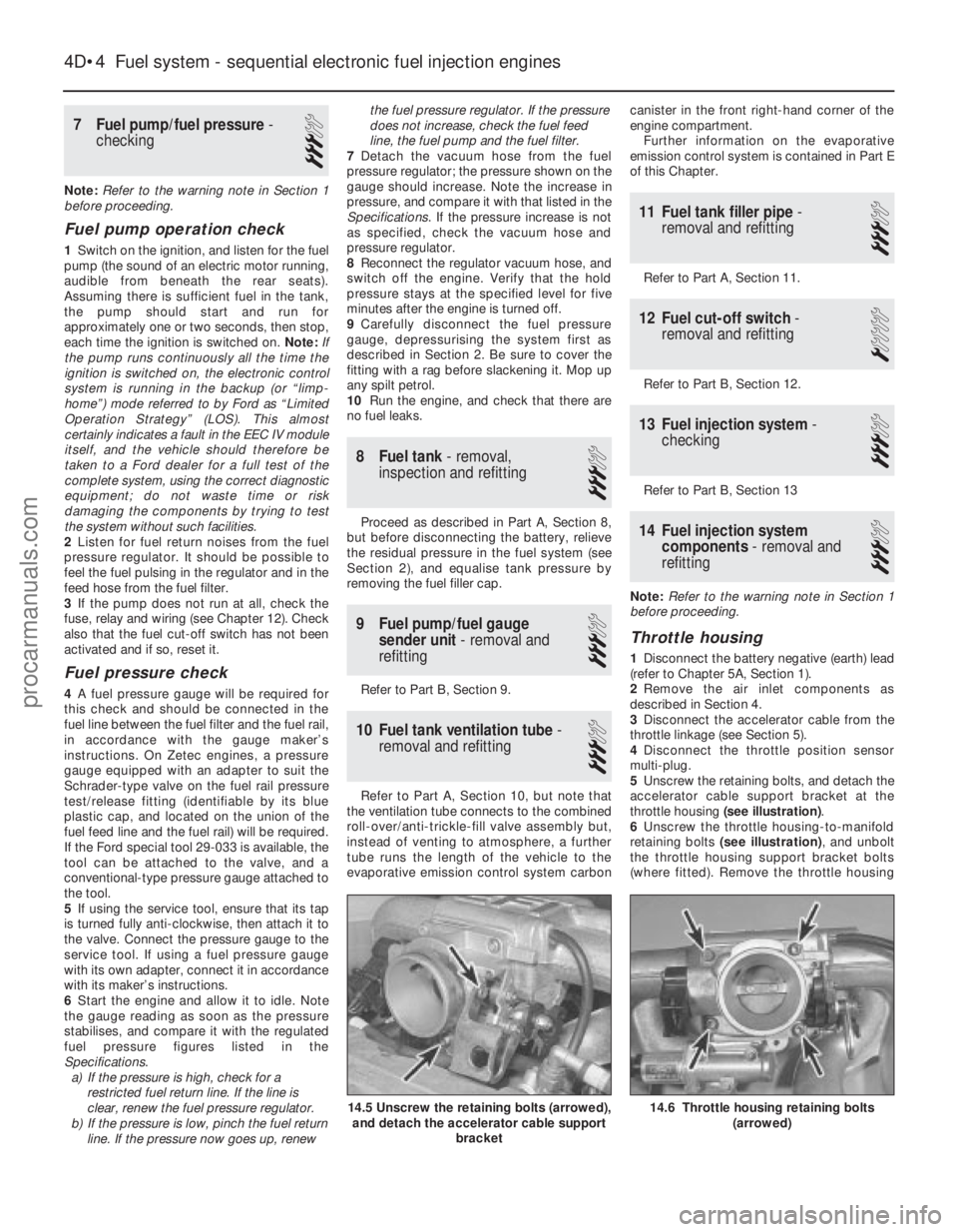
5 Unscrew the retaining bolts, and detach the
accelerator cable support bracket at the
throttle housing (see illustration) .
6 Unscrew the throttle housing-to-manifold
retaining bolts (see illustration) , and unbolt
the throttle housing support bracket bolts
(where fitted). Remove the throttle housing
4D•4 Fuel system - sequential electronic fuel injection engines
14.6 Throttle housing retaining bolts
(arrowed)14.5 Unscrew the retaining bolts (arrowed),and detach the accelerator cable support
bracket
1595Ford Fiesta Remakeprocarmanuals.com
http://vnx.su
Page 148 of 296
and gasket. Discard the gasket - this must be
renewed whenever it is disturbed.
7Refit in the reverse order of removal. Check
that the mating faces are clean, and fit a new
gasket. Adjust the accelerator cable as
described in Section 5 on completion.
Fuel rail and injectors
Note: The following procedure is applicable
mainly to Zetec engines; specific information
for the PTE engine was not available at the
time of writing. However, apart from minor
differences in component attachments, both
engine types are very similar in this area.
8 Relieve the residual pressure in the fuel
system (see Section 2), and equalise tank
pressure by removing the fuel filler cap. Warning: This procedure will
merely relieve the increased
pressure necessary for the
engine to run - remember that
fuel will still be present in the system
components, and take precautions
accordingly before disconnecting any of
them.
9 Disconnect the battery negative (earth) lead
- see Chapter 5A, Section 1.
10 Remove the air inlet components as
described in Section 4.
11 Disconnect the accelerator cable from the
throttle linkage (see Section 5).
12 Disconnect the throttle position sensor
multi-plug.
13 Remove the throttle housing mounting
screws, then detach the throttle housing and gasket from the inlet manifold. Discard the
gasket - this must be renewed whenever it is
disturbed.
14
Detach the crankcase breather hose from
the cylinder head cover, and the fuel pressure
regulator vacuum hose from the inlet
manifold.
15 Releasing the wire clips, unplug the four
fuel injector multi-plugs and the inlet air
temperature sensor multi-plug.
16 Refer to Section 3 and disconnect the fuel
feed and return lines at the quick-release
couplings, then unclip the fuel hoses from the
inlet manifold; use rag to soak up any spilt
fuel. Note: Do not disturb the threaded
couplings at the fuel rail unions unless
absolutely necessary; these are sealed at the
factory. The quick-release couplings will
suffice for all normal service operations.
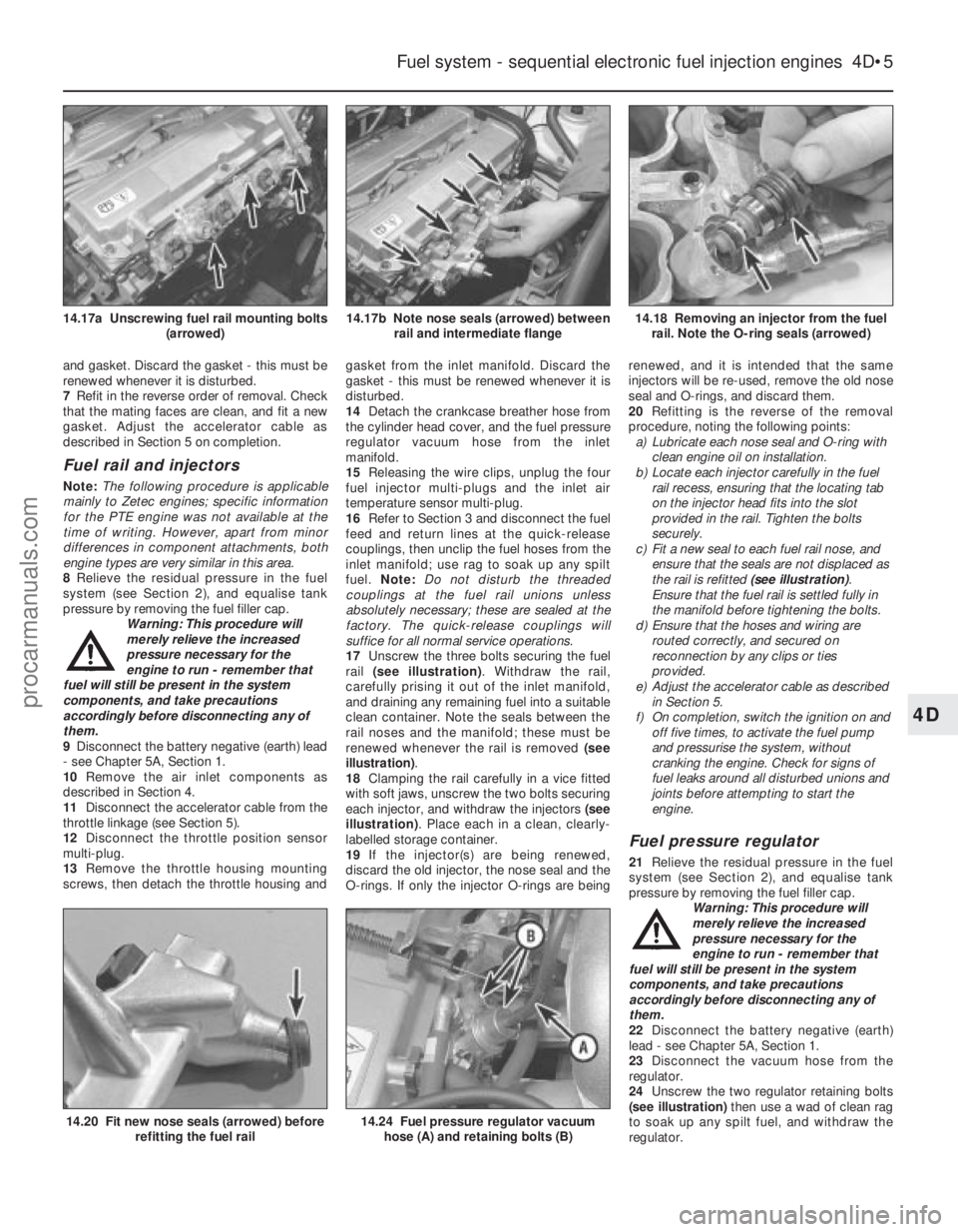
17 Unscrew the three bolts securing the fuel
rail (see illustration) . Withdraw the rail,
carefully prising it out of the inlet manifold,
and draining any remaining fuel into a suitable
clean container. Note the seals between the
rail noses and the manifold; these must be
renewed whenever the rail is removed (see
illustration) .
18 Clamping the rail carefully in a vice fitted
with soft jaws, unscrew the two bolts securing
each injector, and withdraw the injectors (see
illustration) . Place each in a clean, clearly-
labelled storage container.
19 If the injector(s) are being renewed,
discard the old injector, the nose seal and the
O- rings. If only the injector O-rings are being renewed, and it is intended that the same
injectors will be re-used, remove the old nose
seal and O-rings, and discard them.
20
Refitting is the reverse of the removal
procedure, noting the following points:
a) Lubricate each nose seal and O-ring with clean engine oil on installation.
b) Locate each injector carefully in the fuel
rail recess, ensuring that the locating tab
on the injector head fits into the slot
provided in the rail. Tighten the bolts
securely.
c) Fit a new seal to each fuel rail nose, and
ensure that the seals are not displaced as
the rail is refitted (see illustration).
Ensure that the fuel rail is settled fully in
the manifold before tightening the bolts.
d) Ensure that the hoses and wiring are
routed correctly, and secured on
reconnection by any clips or ties
provided.
e) Adjust the accelerator cable as described
in Section 5.
f) On completion, switch the ignition on and off five times, to activate the fuel pump
and pressurise the system, without
cranking the engine. Check for signs of
fuel leaks around all disturbed unions and
joints before attempting to start the
engine.
Fuel pressure regulator
21 Relieve the residual pressure in the fuel
system (see Section 2), and equalise tank
pressure by removing the fuel filler cap.
Warning: This procedure will
merely relieve the increased
pressure necessary for the
engine to run - remember that
fuel will still be present in the system
components, and take precautions
accordingly before disconnecting any of
them.
22 Disconnect the battery negative (earth)
lead - see Chapter 5A, Section 1.
23 Disconnect the vacuum hose from the
regulator.
24 Unscrew the two regulator retaining bolts
(see illustration) then use a wad of clean rag
to soak up any spilt fuel, and withdraw the
regulator.
Fuel system - sequential electronic fuel injection engines 4D•5
14.18 Removing an injector from the fuel rail. Note the O-ring seals (arrowed)14.17b Note nose seals (arrowed) between rail and intermediate flange14.17a Unscrewing fuel rail mounting bolts (arrowed)
14.24 Fuel pressure regulator vacuumhose (A) and retaining bolts (B)14.20 Fit new nose seals (arrowed) before refitting the fuel rail
4D
1595Ford Fiesta Remakeprocarmanuals.com
http://vnx.su
Page 149 of 296
25Refitting is the reverse of the removal
procedure, noting the following points: a) Renew the regulator sealing O-ring
whenever the regulator is disturbed.
Lubricate the new O-ring with clean
engine oil on installation.
b) Locate the regulator carefully in the fuel
rail recess, and tighten the bolts securely.
c) On completion, switch the ignition on and off five times, to activate the fuel pump
and pressurise the system, without
cranking the engine. Check for signs of
fuel leaks around all disturbed unions and
joints before attempting to start the
engine.
Idle speed control valve
26 Disconnect the battery negative (earth)
lead (refer to Chapter 5A, Section 1).
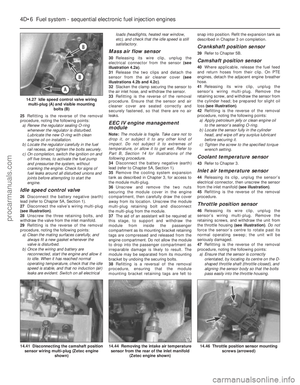
27 Disconnect the valve’s wiring multi-plug
(see illustration) .
28 Unscrew the three retaining bolts, and
withdraw the valve from the inlet manifold.
29 Refitting is the reverse of the removal
procedure, noting the following points: a) Clean the mating surfaces carefully, and
always fit a new gasket whenever the
valve is disturbed.
b) Once the wiring and battery are
reconnected, start the engine and allow it
to idle. When it has reached normal
operating temperature, check that the idle
speed is stable, and that no induction (air)
leaks are evident. Switch on all electrical loads (headlights, heated rear window,
etc), and check that the idle speed is still
satisfactory.
Mass air flow sensor
30
Releasing its wire clip, unplug the
electrical connector from the sensor (see
illustration 4.2a) .
31 Release the two clips and detach the
sensor from the air cleaner cover (see
illustrations 4.2b and 4.2c) .
32 Slacken the clamp securing the sensor to
the air inlet hose, and withdraw the sensor.
33 Refitting is the reverse of the removal
procedure. Ensure that the sensor and air
cleaner cover are seated correctly and
securely fastened, so that there are no air
leaks.
EEC IV engine management
module
Note: The module is fragile. Take care not to
drop it, or subject it to any other kind of
impact. Do not subject it to extremes of
temperature, or allow it to get wet. Refer to
Part B, Section 14 for illustrations of the
following procedure.
34 Disconnect the battery negative (earth)
lead (refer to Chapter 5A, Section 1).
35 Remove the cooling system expansion
tank as described in Chapter 3, for access to
the module multi-plug.
36 Unscrew and remove the two nuts
securing the module cover in the engine
compartment, then carefully draw the cover
away from its location. Unscrew the module
multi-plug retaining bolt and disconnect
the multi-plug from the module.
37 The aid of an assistant will be required at
this stage, to support and withdraw the
module from inside the passenger
compartment as its mounting bracket retaining
tags are compressed and released from the
engine compartment. Do not allow the module
to drop into the passenger compartment as
irreparable damage is likely to result. The
module may be separated from its mounting
bracket by undoing the securing bolts.
38 Refitting is a reversal of the removal
procedure, ensuring that the module
mounting bracket retaining tags are felt to snap into position. Refit the expansion tank as
described in Chapter 3 on completion.
Crankshaft position sensor
39
Refer to Chapter 5B.
Camshaft position sensor
40Where applicable, release the fuel feed
and return hoses from their clip. On PTE
engines, detach the adjacent engine breather
hose.
41 Releasing its wire clip, unplug the
sensor’s wiring multi-plug. Remove the
retaining screw, and withdraw the sensor from
the cylinder head; be prepared for slight oil
loss (see illustration) .
42 Refitting is the reverse of the removal
procedure, noting the following points: a) Apply petroleum jelly or clean engine oil
to the sensor’s sealing O-ring.
b) Locate the sensor fully in the cylinder
head, and wipe off any surplus lubricant
before securing it.
c) Tighten the screw to the specified torque wrench setting.
Coolant temperature sensor
43 Refer to Chapter 3.
Inlet air temperature sensor
44Releasing its clip, unplug the sensor’s
electrical connector, then unscrew the sensor
from the inlet manifold (see illustration).
45 Refitting is the reverse of the removal
procedure.
Throttle position sensor
46 Releasing its wire clip, unplug the
sensor’s wiring multi-plug. Remove the
retaining screws, and withdraw the unit from
the throttle housing (see illustration). Do not
force the sensor’s centre to rotate past its
normal operating sweep; the unit will be
seriously damaged.
47 Refitting is the reverse of the removal
procedure, noting the following points: a) Ensure that the sensor is correctly orientated, by locating its centre on the D-
shaped throttle shaft (throttle closed), and
aligning the sensor body so that the bolts
pass easily into the throttle housing.
4D•6 Fuel system - sequential electronic fuel injection engines
14.46 Throttle position sensor mounting screws (arrowed)14.44 Removing the intake air temperaturesensor from the rear of the inlet manifold
(Zetec engine shown)14.41 Disconnecting the camshaft positionsensor wiring multi-plug (Zetec engine
shown)
14.27 Idle speed control valve wiringmulti-plug (A) and visible mounting bolts (B)
1595Ford Fiesta Remakeprocarmanuals.com
http://vnx.su
Page 150 of 296
b)Tighten the screws evenly and securely
(but do not overtighten them, or the
potentiometer body will be cracked).
Vehicle speed sensor
48 The sensor is mounted at the base of the
speedometer drive cable, and is removed with
the speedometer drive pinion. Refer to the
relevant Section of Chapter 7A or B, as
applicable.
Power steering pressure switch
49 Releasing its clip, unplug the switch’s
electrical connector, then unscrew the switch
from the power steering high pressure pipe.
Place a wad of rag underneath, to catch any
spilt fluid. If a sealing washer is fitted, renew it
if it is worn or damaged.
50 Refitting is the reverse of the removal
procedure; tighten the switch securely, then
top-up the fluid reservoir (see “Weekly
Checks”) to replace any fluid lost from the
system, and bleed out any trapped air (see
Chapter 10).
Oxygen sensor
Note: The sensor is delicate, and will not work
if it is dropped or knocked, if its power supply
is disrupted, or if any cleaning materials are
used on it.
51 Raise and support the front of the vehicle
if required to remove the sensor from
underneath (“see Jacking and vehicle
support” ).
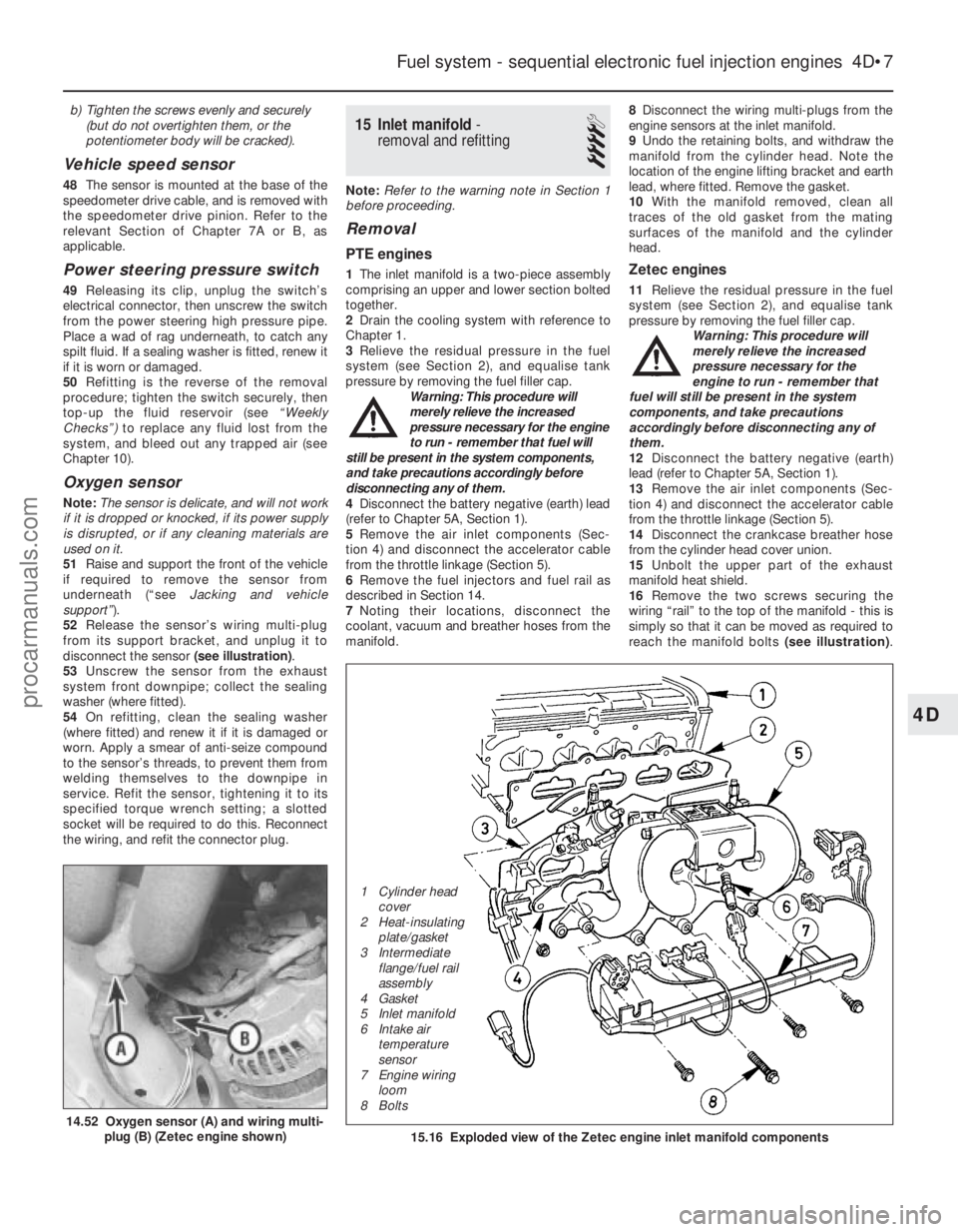
52 Release the sensor’s wiring multi-plug
from its support bracket, and unplug it to
disconnect the sensor (see illustration).
53 Unscrew the sensor from the exhaust
system front downpipe; collect the sealing
washer (where fitted).
54 On refitting, clean the sealing washer
(where fitted) and renew it if it is damaged or
worn. Apply a smear of anti-seize compound
to the sensor’s threads, to prevent them from
welding themselves to the downpipe in
service. Refit the sensor, tightening it to its
specified torque wrench setting; a slotted
socket will be required to do this. Reconnect
the wiring, and refit the connector plug.
15 Inlet manifold -
removal and refitting
4
Note: Refer to the warning note in Section 1
before proceeding.
Removal
PTE engines
1 The inlet manifold is a two-piece assembly
comprising an upper and lower section bolted
together.
2 Drain the cooling system with reference to
Chapter 1.
3 Relieve the residual pressure in the fuel
system (see Section 2), and equalise tank
pressure by removing the fuel filler cap. Warning: This procedure will
merely relieve the increased
pressure necessary for the engine
to run - remember that fuel will
still be present in the system components,
and take precautions accordingly before
disconnecting any of them.
4 Disconnect the battery negative (earth) lead
(refer to Chapter 5A, Section 1).
5 Remove the air inlet components (Sec-
tion 4) and disconnect the accelerator cable
from the throttle linkage (Section 5).
6 Remove the fuel injectors and fuel rail as
described in Section 14.
7 Noting their locations, disconnect the
coolant, vacuum and breather hoses from the
manifold. 8
Disconnect the wiring multi-plugs from the
engine sensors at the inlet manifold.
9 Undo the retaining bolts, and withdraw the
manifold from the cylinder head. Note the
location of the engine lifting bracket and earth
lead, where fitted. Remove the gasket.
10 With the manifold removed, clean all
traces of the old gasket from the mating
surfaces of the manifold and the cylinder
head.Zetec engines
11 Relieve the residual pressure in the fuel
system (see Section 2), and equalise tank
pressure by removing the fuel filler cap. Warning: This procedure will
merely relieve the increased
pressure necessary for the
engine to run - remember that
fuel will still be present in the system
components, and take precautions
accordingly before disconnecting any of
them.
12 Disconnect the battery negative (earth)
lead (refer to Chapter 5A, Section 1).
13 Remove the air inlet components (Sec-
tion 4) and disconnect the accelerator cable
from the throttle linkage (Section 5).
14 Disconnect the crankcase breather hose
from the cylinder head cover union.
15 Unbolt the upper part of the exhaust
manifold heat shield.
16 Remove the two screws securing the
wiring “rail” to the top of the manifold - this is
simply so that it can be moved as required to
reach the manifold bolts (see illustration).
Fuel system - sequential electronic fuel injection engines 4D•7
14.52 Oxygen sensor (A) and wiring multi-
plug (B) (Zetec engine shown)15.16 Exploded view of the Zetec engine inlet manifold components
4D
1595Ford Fiesta Remake
1 Cylinder head
cover
2 Heat-insulating plate/gasket
3 Intermediate flange/fuel rail
assembly
4 Gasket
5 Inlet manifold
6 Intake air temperature
sensor
7 Engine wiring
loom
8 Boltsprocarmanuals.com
http://vnx.su
Page 151 of 296
Unplug the electrical connectors at the
camshaft position sensor and the coolant
temperature sensor, then unclip the wiring
from the ignition coil bracket, and secure it to
the manifold.
17Remove the three screws securing the
wiring “rail” to the rear of the manifold.
Releasing its wire clip, unplug the large
electrical connector (next to the fuel pressure
regulator) to disconnect the wiring of the
manifold components from the engine wiring
loom.
18 Marking or labelling them as they are
unplugged, disconnect the vacuum hoses at
the manifold and throttle housing.
19 Undo the fuel feed and return lines
connecting the engine to the chassis. Plug or
cap all open fittings. 20
Unbolt the earth lead from the cylinder
head rear support plate/engine lifting eye,
then unscrew the bolt securing the support
plate/lifting eye.
21 Unscrew the nuts and bolts securing the
manifold to the cylinder head, and withdraw it.
Take care not to damage vulnerable
components as the manifold assembly is
manoeuvred out of the engine compartment.
22 With the manifold removed, clean all
traces of the old gasket from the mating
surfaces of the manifold and the cylinder head.
Refitting
All engines
23 Refitting is the reverse of the removal
procedure, noting the following points: a) Fit a new gasket, then locate the manifold on the head and install the nuts and bolts.
b) Tighten the nuts/bolts in three or four
equal steps to the specified torque,
working from the centre outwards, to
avoid warping the manifold.
c) Refit the remaining parts in the reverse order of removal - tighten all fasteners to
the torque wrench settings specified
(where given).
d) Where drained, refill the cooling system
as described in Chapter 1.
e) Before starting the engine, check the accelerator cable for correct adjustment
and the throttle linkage for smooth
operation (Section 5).
f) When the engine is fully warmed-up,
check for signs of fuel, inlet and/or
vacuum leaks.
4D•8 Fuel system - sequential electronic fuel injection engines
1595Ford Fiesta Remakeprocarmanuals.com
http://vnx.su
Page 153 of 296
into the engine induction system and thence
into the combustion chambers. This
arrangement eliminates any fuel mixture
control problems. The operating principles for
the system used on the Endura-E engine are
basically the same as just described with
revisions to the component locations and
hose arrangement.On CVH and PTE engines, a closed-circuit
type crankcase ventilation system is used, the
function of which is basically the same as that
described for the HCS engine type, but the
breather hose connects directly to the rocker
cover. The oil filler cap incorporates a
separate filter in certain applications. On Zetec engines, the crankcase ventilation
system main components are the oil
separator mounted on the front (radiator) side
of the cylinder block/crankcase, and the
Positive Crankcase Ventilation (PCV) valve set
in a rubber grommet in the separator’s left-
hand upper end. The associated pipework
consists of a crankcase breather pipe and two
flexible hoses connecting the PCV valve to a
union on the left-hand end of the inlet
manifold, and a crankcase breather hose
connecting the cylinder head cover to the air
cleaner assembly. A small foam filter in the air
cleaner prevents dirt from being drawn
directly into the engine.
Evaporative emissions control system
This system is fitted to minimise the escape
of unburned hydrocarbons into the
atmosphere. Fuel evaporative emissions
control systems are limited on vehicles
meeting earlier emissions regulations;
carburettor float chambers are vented
internally, whilst fuel tanks vent to atmosphere
through a combined roll-over/anti-trickle-fill
valve. On vehicles meeting the more stringent
emissions regulations, the fuel tank filler cap
is sealed, and a charcoal canister is used to
collect and store petrol vapours generated in
the tank when the vehicle is parked. When the
engine is running, the vapours are cleared
from the canister (under the control of the
EEC IV engine management module via the
canister-purge solenoid valve) into the inlet
tract, to be burned by the engine during
normal combustion. To ensure that the engine runs correctly
when it is cold and/or idling, and to protect
the catalytic converter from the effects of an
over-rich mixture, the canister-purge solenoid
valve is not opened by the EEC IV module
until the engine is fully warmed-up and
running under part-load; the solenoid valve is
then switched on and off, to allow the stored
vapour to pass into the inlet tract.
Pulse-air system
This system consists of the pulse-air
solenoid valve, the pulse-air valve itself, the
delivery tubing, a pulse-air filter, and on some
models, a check valve. The system injects
filtered air directly into the exhaust ports,
using the pressure variations in the exhaust
gases to draw air through from the filter housing; air will flow into the exhaust only
when its pressure is below atmospheric. The
pulse-air valve can allow gases to flow only
one way, so there is no risk of hot exhaust
gases flowing back into the filter.
The system’s primary function is raise
exhaust gas temperatures on start-up, thus
reducing the amount of time taken for the
catalytic converter to reach operating
temperature. Until this happens, the system
reduces emissions of unburned hydrocarbon
particles (HC) and carbon monoxide (CO) by
ensuring that a considerable proportion of
these substances remaining in the exhaust
gases after combustion are burned up, either
in the manifold itself or in the catalytic
converter.
To ensure that the system does not upset
the smooth running of the engine under
normal driving conditions, it is linked by the
pulse-air solenoid valve to the EEC IV module,
so that it only functions during engine warm-
up, when the oxygen sensor is not influencing
the fuel/air mixture ratio.
Catalytic converter
Catalytic converters have been introduced
progressively on all models in the range, to
meet the various emissions regulations.
The catalytic converter is located in the
exhaust system, and operates in conjunction
with an exhaust gas oxygen sensor to reduce
exhaust gas emissions. The catalytic
converter uses precious metals (platinum and
palladium or rhodium) as catalysts to speed
up the reaction between the pollutants and
the oxygen in the vehicle’s exhaust gases, CO
and HC being oxidised to form H
2O and CO2and (in the three-way type of catalytic
converter) NO
xbeing reduced to N2. Note :
The catalytic converter is not a filter in the
physical sense; its function is to promote a
chemical reaction, but it is not itself affected
by that reaction. The converter consists of an element (or
“substrate”) of ceramic honeycomb, coated
with a combination of precious metals in such
a way as to produce a vast surface area over
which the exhaust gases must flow; the whole
being mounted in a stainless-steel box. A
simple “oxidation” (or “two-way”) catalytic
converter can deal with CO and HC only,
while a “reduction” (or “three-way”) catalytic
converter can deal with CO, HC and NO
x.
Three-way catalytic converters are further
sub-divided into “open-loop” (or
“unregulated”) converters, which can remove
50 to 70% of pollutants and “closed-loop”
(also known as “controlled” or “regulated”)
converters, which can remove over 90% of
pollutants.
In order for a closed-loop catalytic
converter to operate effectively, the air/fuel
mixture must be very accurately controlled,
and this is achieved by measuring the oxygen
content of the exhaust gas. The oxygen
sensor transmits information on the exhaust
gas oxygen content to the EEC IV engine management module, which adjusts the
air/fuel mixture strength accordingly.
The sensor has a built-in heating element
which is controlled by the EEC IV module, in
order to bring the sensor’s tip to an efficient
operating temperature as rapidly as possible.
The sensor’s tip is sensitive to oxygen, and
sends the module a varying voltage
depending on the amount of oxygen in the
exhaust gases; if the inlet air/fuel mixture is
too rich, the sensor sends a high-voltage
signal. The voltage falls as the mixture
weakens. Peak conversion efficiency of all
major pollutants occurs if the inlet air/fuel
mixture is maintained at the chemically-
correct ratio for the complete combustion of
petrol - 14.7 parts (by weight) of air to 1 part
of fuel (the “stoichiometric” ratio). The sensor
output voltage alters in a large step at this
point, the module using the signal change as
a reference point, and correcting the inlet
air/fuel mixture accordingly by altering the fuel
injector pulse width (injector opening time). Removal and refitting procedures for
the oxygen sensor are given in Parts B, C
and D of this Chapter according to fuel
system type.
2 Exhaust system - renewal
2
Warning: Inspection and repair
of exhaust system components
should be done only after
enough time has elapsed after
driving the vehicle to allow the system
components to cool completely. This
applies particularly to the catalytic
converter, which runs at very high
temperatures. Also, when working under
the vehicle, make sure it is securely
supported on axle stands.
If the exhaust system components are
extremely corroded or rusted together, they
will probably have to be cut from the exhaust
system. The most convenient way of
accomplishing this is to have a quick-fit
exhaust repair specialist remove the corroded
sections. Alternatively, you can simply cut off
the old components with a hacksaw. If you do
decide to tackle the job at home, be sure to
wear eye protection, to protect your eyes from
metal chips, and work gloves, to protect your
hands. If the production-fit system is still
fitted, it must be cut for the service-
replacement system sections to fit. The best
way of determining the correct cutting point is
to obtain the new centre or rear section first
then, with the old system removed, lay the
two side by side on the ground. It should now
be relatively easy to determine where the old
system needs to be cut, and it can be marked
accordingly. Remember to allow for the
overlap where the two sections will plug
together.
4E•2 Exhaust and emission control systems
1595Ford Fiesta Remakeprocarmanuals.com
http://vnx.su
Page 155 of 296
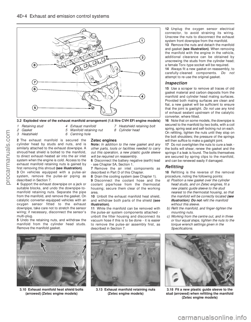
2The exhaust manifold is secured the
cylinder head by studs and nuts, and is
similarly attached to the exhaust downpipe. A
shroud/heat shield is bolted to the manifold,
to direct exhaust-heated air into the air inlet
system when the engine is cold. Access to the
exhaust manifold retaining nuts is gained by
first removing this shroud (see illustration).
3 On vehicles equipped with a pulse-air
system, remove the pulse-air piping as
described in Section 7.
4 Support the exhaust downpipe on a jack or
suitable blocks, and undo the downpipe-to-
manifold retaining nuts. Separate the pipe
from the manifold, and remove the gasket. On
catalytic converter-equipped vehicles with an
oxygen sensor fitted to the exhaust
downpipe, take care not to stretch the sensor
wiring; if necessary, disconnect the sensor’s
multi-plug.
5 Undo the retaining nuts, and withdraw the
manifold from the cylinder head studs.
Remove the manifold gasket.Zetec enginesNote: In addition to the new gasket and any
other parts, tools or facilities needed to carry
out this operation, a new plastic guide sleeve
will be required on reassembly.
6 Disconnect the battery negative (earth) lead
- see Chapter 5A, Section 1.
7 Remove the air inlet components as
described in Part D of this Chapter.
8 Drain the cooling system (see Chapter 1).
9 Disconnect the coolant hose and the
coolant pipe/hose from the thermostat
housing; secure them clear of the working
area.
10 Unbolt the exhaust manifold heat shield,
and withdraw both parts of the shield (see
illustration) .
11 While the manifold can be removed with
the pulse-air system components attached -
unbolt the filter housing and disconnect its
vacuum hose if this is to be done - it is easier
to remove the pulse-air assembly first, as
described in Section 7. 12
Unplug the oxygen sensor electrical
connector, to avoid straining its wiring.
Unscrew the nuts to disconnect the exhaust
system front downpipe from the manifold.
13 Remove the nuts and detach the manifold
and gasket (see illustration) . When removing
the manifold with the engine in the vehicle,
additional clearance can be obtained by
unscrewing the studs from the cylinder head;
a female Torx-type socket will be required.
14 Always fit a new gasket on reassembly, to
carefully-cleaned components. Do not
attempt to re-use the original gasket.
Inspection
15 Use a scraper to remove all traces of old
gasket material and carbon deposits from the
manifold and cylinder head mating surfaces.
Provided both mating surfaces are clean and
flat, a new gasket will be sufficient to ensure
that the joint is gastight. Do not use any kind
of exhaust sealant upstream of the catalytic
converter, where fitted.
16 Note that on some models, the downpipe is
secured to the manifold by two bolts, with a coil
spring, spring seat and self-locking nut on each.
On refitting, tighten the nuts until they stop on
the bolt shoulders; the pressure of the springs
will then suffice to make a gastight joint.
17 Do not overtighten the nuts to cure a leak -
the bolts will shear; renew the gasket and the
springs if a leak is found. The bolts themselves
are secured by spring clips to the manifold,
and can be renewed easily if damaged.
Refitting
18 Refitting is the reverse of the removal
procedure, noting the following points: a) Position a new gasket over the cylinder head studs, and on Zetec engines, fit a
new plastic guide sleeve to the stud
nearest to the thermostat housing, so that
the manifold will be correctly located (see
illustration) . Do notrefit the manifold
without this sleeve.
b) Refit the manifold, and finger-tighten the
mounting nuts.
c) Working from the centre out, and in three or four equal steps, tighten the nuts to the
torque wrench settings given in the
Specifications.
4E•4 Exhaust and emission control systems
3.18 Fit a new plastic guide sleeve to the
stud (arrowed) when refitting the manifold
(Zetec engine models)3.13 Exhaust manifold retaining nuts(Zetec engine models)3.10 Exhaust manifold heat shield bolts(arrowed) (Zetec engine models)
3.2 Exploded view of the exhaust manifold arrangement (1.6 litre CVH E\
Fi engine models)
1 Retaining stud
2 Gasket
3 Heatshield 4 Exhaust manifold
5 Manifold retaining nut
6 Centring hole 7 Heatshield retaining bolt
8 Cylinder head
1595Ford Fiesta Remakeprocarmanuals.com
http://vnx.su
Page 163 of 296
6 Alternator-
removal and refitting
2
Removal
1 Disconnect the battery negative (earth) lead
(refer to Section 1).
2 Chock the rear wheels then jack up the
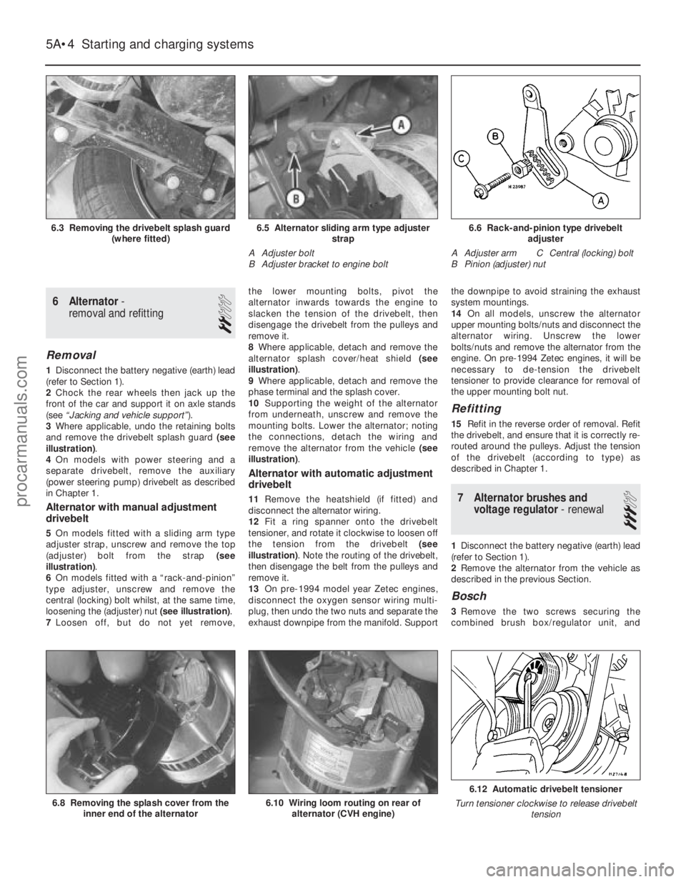
front of the car and support it on axle stands
(see “Jacking and vehicle support” ).
3 Where applicable, undo the retaining bolts
and remove the drivebelt splash guard (see
illustration) .
4 On models with power steering and a
separate drivebelt, remove the auxiliary
(power steering pump) drivebelt as described
in Chapter 1.
Alternator with manual adjustment
drivebelt
5 On models fitted with a sliding arm type
adjuster strap, unscrew and remove the top
(adjuster) bolt from the strap (see
illustration) .
6 On models fitted with a “rack-and-pinion”
type adjuster, unscrew and remove the
central (locking) bolt whilst, at the same time,
loosening the (adjuster) nut (see illustration).
7 Loosen off, but do not yet remove, the lower mounting bolts, pivot the
alternator inwards towards the engine to
slacken the tension of the drivebelt, then
disengage the drivebelt from the pulleys and
remove it.
8
Where applicable, detach and remove the
alternator splash cover/heat shield (see
illustration) .
9 Where applicable, detach and remove the
phase terminal and the splash cover.
10 Supporting the weight of the alternator
from underneath, unscrew and remove the
mounting bolts. Lower the alternator; noting
the connections, detach the wiring and
remove the alternator from the vehicle (see
illustration) .
Alternator with automatic adjustment
drivebelt
11Remove the heatshield (if fitted) and
disconnect the alternator wiring.
12 Fit a ring spanner onto the drivebelt
tensioner, and rotate it clockwise to loosen off
the tension from the drivebelt (see
illustration) . Note the routing of the drivebelt,
then disengage the belt from the pulleys and
remove it.
13 On pre-1994 model year Zetec engines,
disconnect the oxygen sensor wiring multi-
plug, then undo the two nuts and separate the
exhaust downpipe from the manifold. Support the downpipe to avoid straining the exhaust
system mountings.
14
On all models, unscrew the alternator
upper mounting bolts/nuts and disconnect the
alternator wiring. Unscrew the lower
bolts/nuts and remove the alternator from the
engine. On pre-1994 Zetec engines, it will be
necessary to de-tension the drivebelt
tensioner to provide clearance for removal of
the upper mounting bolt nut.
Refitting
15 Refit in the reverse order of removal. Refit
the drivebelt, and ensure that it is correctly re-
routed around the pulleys. Adjust the tension
of the drivebelt (according to type) as
described in Chapter 1.
7 Alternator brushes and voltage regulator - renewal
3
1Disconnect the battery negative (earth) lead
(refer to Section 1).
2 Remove the alternator from the vehicle as
described in the previous Section.
Bosch
3 Remove the two screws securing the
combined brush box/regulator unit, and
5A•4 Starting and charging systems
6.12 Automatic drivebelt tensioner
Turn tensioner clockwise to release drivebelt tension
6.10 Wiring loom routing on rear ofalternator (CVH engine)6.8 Removing the splash cover from the inner end of the alternator
6.6 Rack-and-pinion type drivebelt adjuster
A Adjuster arm C Central (locking) bolt
B Pinion (adjuster) nut6.5 Alternator sliding arm type adjuster strap
A Adjuster bolt
B Adjuster bracket to engine bolt6.3 Removing the drivebelt splash guard (where fitted)
1595Ford Fiesta Remakeprocarmanuals.com
http://vnx.su