1989 FORD FIESTA sensor
[x] Cancel search: sensorPage 48 of 296
23Refer to the procedure in Section 9 when
refitting the camshaft sprocket.
24 Refit and tension the timing belt as
described in Section 8.
25 Lubricate the hydraulic tappets with
hypoid oil before refitting them into their
original locations in the cylinder head.
26 Lubricate and refit the rocker arms and
guides in their original sequence, use new
nuts and tighten them to the specified torque
setting. It is essential, before each rocker arm
is installed and its nut tightened, that the
respective cam follower is positioned at its
lowest point (in contact with the cam base
circle). Turn the cam (using the crankshaft
pulley bolt) as necessary to achieve this.
27 Refit the rocker cover as described in
Section 4.
28 Refit the remaining components with
reference to the relevant Sections in this
Chapter or elsewhere in the manual.
29 On completion, reconnect the battery
negative lead.
12 Cylinder head -
removal and refitting
4
Removal
Note: The following procedure describes
removal and refitting of the cylinder head
complete with inlet and exhaust manifolds. If
wished, the manifolds may be removed first,
as described in the relevant Part of Chapter 4,
and the cylinder head then removed on its
own.
1 On fuel-injected engines, depressurise the
fuel system as described in Chapter 4B or 4C.
2 Disconnect the battery negative (earth) lead
(refer to Chapter 5A, Section 1).
3 Refer to Chapter 1 and drain the cooling
system. 4
Remove the rocker cover as described in
Section 4.
5 Disconnect the accelerator and choke
cables as applicable (refer to the relevant Part
of Chapter 4).
6 Loosen off the retaining clips and
disconnect the upper coolant hose, the
expansion tank hose and the heater hose
from the thermostat housing. Also disconnect
the heater hose from the inlet manifold.
7 On CFi models, disconnect the heated
coolant hose from the injector unit.
8 On EFi and SEFi models, disconnect the
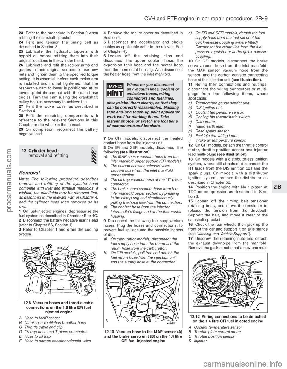
following (see illustration) :
a) The MAP sensor vacuum hose from the inlet manifold upper section (EFi models).
b) The carbon canister solenoid valve
vacuum hose from the inlet manifold
upper section.
c) The oil trap vacuum hose at the “T” piece
connector.
d) The brake servo vacuum hose from the
inlet manifold upper section by pressing
in the clamp ring and simultaneously
pulling the hose free from the connection.
e) The coolant hose from the injector
intermediate flange and at the thermostat
housing.
9 Disconnect the following fuel supply/return
hoses. Plug the hoses and connections, to
prevent fuel spillage and the possible ingress
of dirt.
a) On carburettor models, disconnect the fuel supply hose from the pump and the
return hose from the carburettor.
b) On CFi models, pull free and detach the
fuel return hose from the injection unit
and the supply hose at the connector. c) On EFi and SEFi models, detach the fuel
supply hose from the fuel rail or at the
quick-release coupling (where fitted).
Disconnect the return line from the fuel
pressure regulator or at the quick-release
coupling.
10 On CFi models, disconnect the brake
servo vacuum hose from the inlet manifold,
the MAP sensor vacuum hose from the
sensor, and the carbon canister connecting
hose at the injection unit (see illustration).
11 Noting their connections and routings,
disconnect the wiring connectors or multi-
plugs from the following items, where
applicable:
a) Temperature gauge sender unit.
b) DIS ignition coil.
c) Coolant temperature sensor.
d) Cooling fan thermostatic switch.
e) Carburettor.
f) Radio earth lead.
g) Road speed sensor.
h) Fuel injector wiring loom.
i) Intake air temperature sensor.
12 On CFi models, detach the throttle control
motor, throttle position sensor and injector
lead multi-plugs (see illustration) .
13 On models with a distributorless ignition
system, where still attached, disconnect the
HT leads from the DIS ignition coil and the
spark plugs. On models with a distributor
ignition system, remove the distributor as
described in Chapter 5B.
14 Position the engine with No 1 piston at
TDC on compression as described in Sec-
tion 3.
15 Loosen off the timing belt tensioner
retaining bolts, and move the tensioner to
release the tension from the drivebelt.
Support the belt, and move it clear of the
camshaft sprocket.
16 Chock the rear wheels then jack up the
front of the car and support it on axle stands
(see “Jacking and Vehicle Support” ).
17 Unscrew the retaining nuts and detach
the exhaust downpipe from the manifold.
Remove the gasket; note that a new one must
CVH and PTE engine in-car repair procedures 2B•9
12.12 Wiring connections to be detached on the 1.4 litre CFi fuel injected engine
A Coolant temperature sensor
B Throttle plate control motor
C Throttle position sensor
D Injector
12.10 Vacuum hose to the MAP sensor (A)
and the brake servo unit (B) on the 1.4 litre
CFi fuel-injected engine
12.8 Vacuum hoses and throttle cableconnections on the 1.6 litre EFi fuel injected engine
A Hose to MAP sensor
B Crankcase ventilation breather hose
C Throttle cable and clip
D Oil trap hose and T-piece connector
E Hose to oil trap
F Hose to carbon canister solenoid valve
2B
1595Ford Fiesta Remake
Whenever you disconnect
any vacuum lines, coolant or
emissions hoses, wiring
connectors and fuel lines,
always label them clearly, so that they
can be correctly reassembled. Masking
tape and/or a touch-up paint applicator
work well for marking items. Take
instant photos, or sketch the locations
of components and brackets.
procarmanuals.com
http://vnx.su
Page 49 of 296
be fitted on reassembly. Tie the downpipe up
to support it.
18Before it is released and removed, the
cylinder head must first have cooled down to
room temperature (about 20ºC).
19 Unscrew the cylinder head retaining bolts
progressively in the reverse order to that
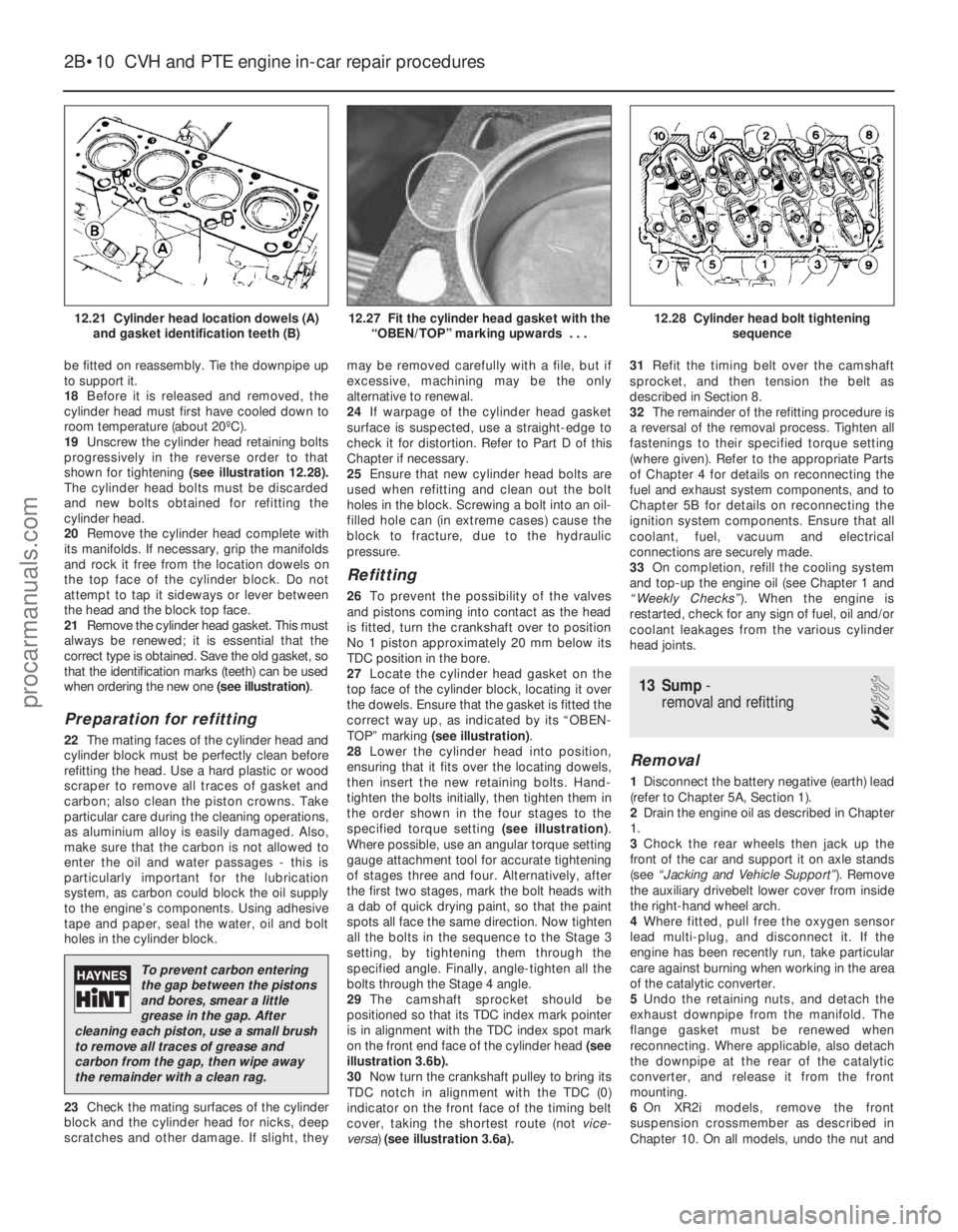
shown for tightening (see illustration 12.28).
The cylinder head bolts must be discarded
and new bolts obtained for refitting the
cylinder head.
20 Remove the cylinder head complete with
its manifolds. If necessary, grip the manifolds
and rock it free from the location dowels on
the top face of the cylinder block. Do not
attempt to tap it sideways or lever between
the head and the block top face.
21 Remove the cylinder head gasket. This must
always be renewed; it is essential that the
correct type is obtained. Save the old gasket, so
that the identification marks (teeth) can be used
when ordering the new one (see illustration).
Preparation for refitting
22The mating faces of the cylinder head and
cylinder block must be perfectly clean before
refitting the head. Use a hard plastic or wood
scraper to remove all traces of gasket and
carbon; also clean the piston crowns. Take
particular care during the cleaning operations,
as aluminium alloy is easily damaged. Also,
make sure that the carbon is not allowed to
enter the oil and water passages - this is
particularly important for the lubrication
system, as carbon could block the oil supply
to the engine’s components. Using adhesive
tape and paper, seal the water, oil and bolt
holes in the cylinder block.
23 Check the mating surfaces of the cylinder
block and the cylinder head for nicks, deep
scratches and other damage. If slight, they may be removed carefully with a file, but if
excessive, machining may be the only
alternative to renewal.
24
If warpage of the cylinder head gasket
surface is suspected, use a straight-edge to
check it for distortion. Refer to Part D of this
Chapter if necessary.
25 Ensure that new cylinder head bolts are
used when refitting and clean out the bolt
holes in the block. Screwing a bolt into an oil-
filled hole can (in extreme cases) cause the
block to fracture, due to the hydraulic
pressure.
Refitting
26 To prevent the possibility of the valves
and pistons coming into contact as the head
is fitted, turn the crankshaft over to position
No 1 piston approximately 20 mm below its
TDC position in the bore.
27 Locate the cylinder head gasket on the
top face of the cylinder block, locating it over
the dowels. Ensure that the gasket is fitted the
correct way up, as indicated by its “OBEN-
TOP” marking (see illustration) .
28 Lower the cylinder head into position,
ensuring that it fits over the locating dowels,
then insert the new retaining bolts. Hand-
tighten the bolts initially, then tighten them in
the order shown in the four stages to the
specified torque setting (see illustration).
Where possible, use an angular torque setting
gauge attachment tool for accurate tightening
of stages three and four. Alternatively, after
the first two stages, mark the bolt heads with
a dab of quick drying paint, so that the paint
spots all face the same direction. Now tighten
all the bolts in the sequence to the Stage 3
setting, by tightening them through the
specified angle. Finally, angle-tighten all the
bolts through the Stage 4 angle.
29 The camshaft sprocket should be
positioned so that its TDC index mark pointer
is in alignment with the TDC index spot mark
on the front end face of the cylinder head (see
illustration 3.6b).
30 Now turn the crankshaft pulley to bring its
TDC notch in alignment with the TDC (0)
indicator on the front face of the timing belt
cover, taking the shortest route (not vice-
versa) (see illustration 3.6a). 31
Refit the timing belt over the camshaft
sprocket, and then tension the belt as
described in Section 8.
32 The remainder of the refitting procedure is
a reversal of the removal process. Tighten all
fastenings to their specified torque setting
(where given). Refer to the appropriate Parts
of Chapter 4 for details on reconnecting the
fuel and exhaust system components, and to
Chapter 5B for details on reconnecting the
ignition system components. Ensure that all
coolant, fuel, vacuum and electrical
connections are securely made.
33 On completion, refill the cooling system
and top-up the engine oil (see Chapter 1 and
“Weekly Checks” ). When the engine is
restarted, check for any sign of fuel, oil and/or
coolant leakages from the various cylinder
head joints.
13 Sump -
removal and refitting
2
Removal
1 Disconnect the battery negative (earth) lead
(refer to Chapter 5A, Section 1).
2 Drain the engine oil as described in Chapter
1.
3 Chock the rear wheels then jack up the
front of the car and support it on axle stands
(see “Jacking and Vehicle Support” ). Remove
the auxiliary drivebelt lower cover from inside
the right-hand wheel arch.
4 Where fitted, pull free the oxygen sensor
lead multi-plug, and disconnect it. If the
engine has been recently run, take particular
care against burning when working in the area
of the catalytic converter.
5 Undo the retaining nuts, and detach the
exhaust downpipe from the manifold. The
flange gasket must be renewed when
reconnecting. Where applicable, also detach
the downpipe at the rear of the catalytic
converter, and release it from the front
mounting.
6 On XR2i models, remove the front
suspension crossmember as described in
Chapter 10. On all models, undo the nut and
2B•10 CVH and PTE engine in-car repair procedures
12.28 Cylinder head bolt tightening
sequence12.27 Fit the cylinder head gasket with the“OBEN/TOP” marking upwards . . .12.21 Cylinder head location dowels (A)and gasket identification teeth (B)
1595Ford Fiesta Remake
To prevent carbon entering
the gap between the pistons
and bores, smear a little
grease in the gap. After
cleaning each piston, use a small brush
to remove all traces of grease and
carbon from the gap, then wipe away
the remainder with a clean rag.
procarmanuals.com
http://vnx.su
Page 62 of 296
and evenly the pressure of the valve springs
on the caps.
5Withdraw the caps, noting their markings
and the presence of the locating dowels, then
remove the camshafts and withdraw their oil
seals. The inlet camshaft can be identified by
the reference lobe for the camshaft position
sensor; therefore, there is no need to mark the
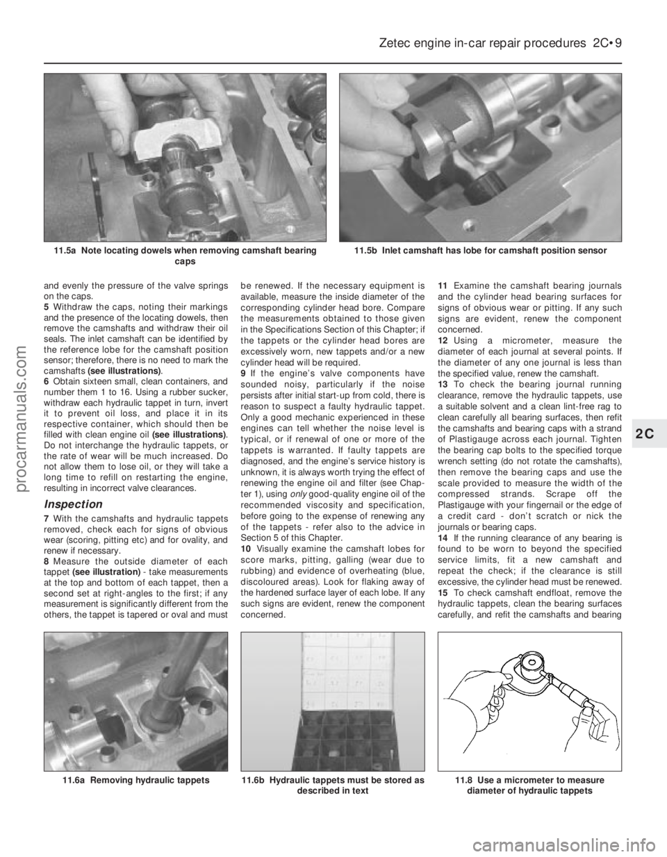
camshafts (see illustrations) .
6 Obtain sixteen small, clean containers, and
number them 1 to 16. Using a rubber sucker,
withdraw each hydraulic tappet in turn, invert
it to prevent oil loss, and place it in its
respective container, which should then be
filled with clean engine oil (see illustrations).
Do not interchange the hydraulic tappets, or
the rate of wear will be much increased. Do
not allow them to lose oil, or they will take a
long time to refill on restarting the engine,
resulting in incorrect valve clearances.
Inspection
7 With the camshafts and hydraulic tappets
removed, check each for signs of obvious
wear (scoring, pitting etc) and for ovality, and
renew if necessary.
8 Measure the outside diameter of each
tappet (see illustration) - take measurements
at the top and bottom of each tappet, then a
second set at right-angles to the first; if any
measurement is significantly different from the
others, the tappet is tapered or oval and must be renewed. If the necessary equipment is
available, measure the inside diameter of the
corresponding cylinder head bore. Compare
the measurements obtained to those given
in the Specifications Section of this Chapter; if
the tappets or the cylinder head bores are
excessively worn, new tappets and/or a new
cylinder head will be required.
9
If the engine’s valve components have
sounded noisy, particularly if the noise
persists after initial start-up from cold, there is
reason to suspect a faulty hydraulic tappet.
Only a good mechanic experienced in these
engines can tell whether the noise level is
typical, or if renewal of one or more of the
tappets is warranted. If faulty tappets are
diagnosed, and the engine’s service history is
unknown, it is always worth trying the effect of
renewing the engine oil and filter (see Chap-
ter 1), using onlygood-quality engine oil of the
recommended viscosity and specification,
before going to the expense of renewing any
of the tappets - refer also to the advice in
Section 5 of this Chapter.
10 Visually examine the camshaft lobes for
score marks, pitting, galling (wear due to
rubbing) and evidence of overheating (blue,
discoloured areas). Look for flaking away of
the hardened surface layer of each lobe. If any
such signs are evident, renew the component
concerned. 11
Examine the camshaft bearing journals
and the cylinder head bearing surfaces for
signs of obvious wear or pitting. If any such
signs are evident, renew the component
concerned.
12 Using a micrometer, measure the
diameter of each journal at several points. If
the diameter of any one journal is less than
the specified value, renew the camshaft.
13 To check the bearing journal running
clearance, remove the hydraulic tappets, use
a suitable solvent and a clean lint-free rag to
clean carefully all bearing surfaces, then refit
the camshafts and bearing caps with a strand
of Plastigauge across each journal. Tighten
the bearing cap bolts to the specified torque
wrench setting (do not rotate the camshafts),
then remove the bearing caps and use the
scale provided to measure the width of the
compressed strands. Scrape off the
Plastigauge with your fingernail or the edge of
a credit card - don’t scratch or nick the
journals or bearing caps.
14 If the running clearance of any bearing is
found to be worn to beyond the specified
service limits, fit a new camshaft and
repeat the check; if the clearance is still
excessive, the cylinder head must be renewed.
15 To check camshaft endfloat, remove the
hydraulic tappets, clean the bearing surfaces
carefully, and refit the camshafts and bearing
Zetec engine in-car repair procedures 2C•9
11.6a Removing hydraulic tappets
11.5b Inlet camshaft has lobe for camshaft position sensor11.5a Note locating dowels when removing camshaft bearing caps
11.8 Use a micrometer to measurediameter of hydraulic tappets11.6b Hydraulic tappets must be stored as described in text
2C
1595Ford Fiesta Remakeprocarmanuals.com
http://vnx.su
Page 64 of 296
5Disconnect the accelerator cable from the
throttle linkage as described in Chapter 4D.
Secure the cable clear of the engine/
transmission.
6 Remove the auxiliary drivebelt (see Chap-
ter 1).
7 Remove the three screws securing the
wiring “rail” to the rear of the manifold.
Releasing its wire clip, unplug the large
electrical connector (next to the fuel pressure
regulator) to disconnect the engine wiring from
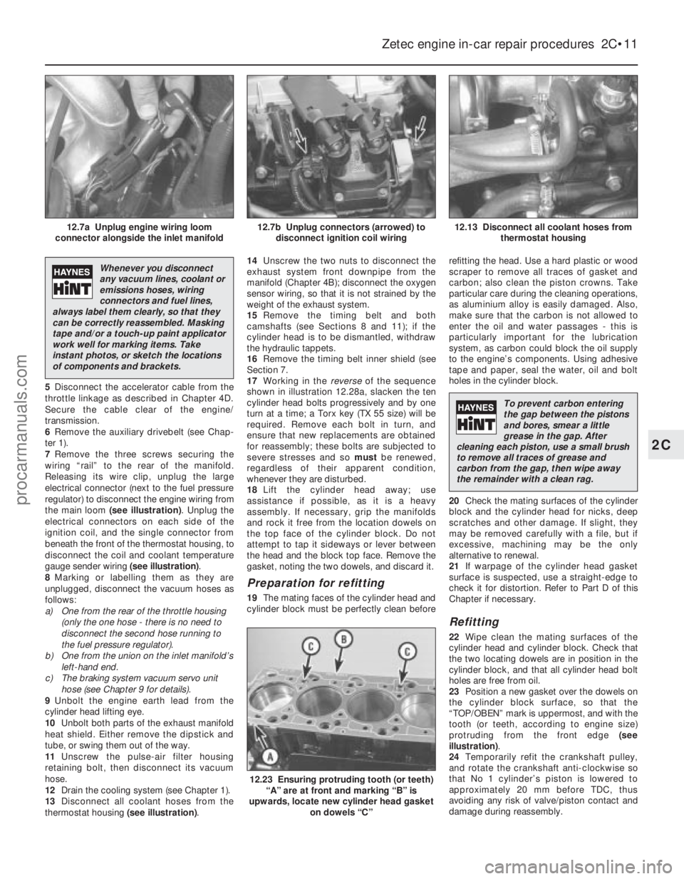
the main loom (see illustration) . Unplug the
electrical connectors on each side of the
ignition coil, and the single connector from
beneath the front of the thermostat housing, to
disconnect the coil and coolant temperature
gauge sender wiring (see illustration).
8 Marking or labelling them as they are
unplugged, disconnect the vacuum hoses as
follows:
a) One from the rear of the throttle housing
(only the one hose - there is no need to
disconnect the second hose running to
the fuel pressure regulator).
b) One from the union on the inlet manifold’s
left-hand end.
c) The braking system vacuum servo unit hose (see Chapter 9 for details).
9 Unbolt the engine earth lead from the
cylinder head lifting eye.
10 Unbolt both parts of the exhaust manifold
heat shield. Either remove the dipstick and
tube, or swing them out of the way.
11 Unscrew the pulse-air filter housing
retaining bolt, then disconnect its vacuum
hose.
12 Drain the cooling system (see Chapter 1).
13 Disconnect all coolant hoses from the
thermostat housing (see illustration).14
Unscrew the two nuts to disconnect the
exhaust system front downpipe from the
manifold (Chapter 4B); disconnect the oxygen
sensor wiring, so that it is not strained by the
weight of the exhaust system.
15 Remove the timing belt and both
camshafts (see Sections 8 and 11); if the
cylinder head is to be dismantled, withdraw
the hydraulic tappets.
16 Remove the timing belt inner shield (see
Section 7.
17 Working in the reverseof the sequence
shown in illustration 12.28a, slacken the ten
cylinder head bolts progressively and by one
turn at a time; a Torx key (TX 55 size) will be
required. Remove each bolt in turn, and
ensure that new replacements are obtained
for reassembly; these bolts are subjected to
severe stresses and so mustbe renewed,
regardless of their apparent condition,
whenever they are disturbed.
18 Lift the cylinder head away; use
assistance if possible, as it is a heavy
assembly. If necessary, grip the manifolds
and rock it free from the location dowels on
the top face of the cylinder block. Do not
attempt to tap it sideways or lever between
the head and the block top face. Remove the
gasket, noting the two dowels, and discard it.
Preparation for refitting
19 The mating faces of the cylinder head and
cylinder block must be perfectly clean before refitting the head. Use a hard plastic or wood
scraper to remove all traces of gasket and
carbon; also clean the piston crowns. Take
particular care during the cleaning operations,
as aluminium alloy is easily damaged. Also,
make sure that the carbon is not allowed to
enter the oil and water passages - this is
particularly important for the lubrication
system, as carbon could block the oil supply
to the engine’s components. Using adhesive
tape and paper, seal the water, oil and bolt
holes in the cylinder block.
20
Check the mating surfaces of the cylinder
block and the cylinder head for nicks, deep
scratches and other damage. If slight, they
may be removed carefully with a file, but if
excessive, machining may be the only
alternative to renewal.
21 If warpage of the cylinder head gasket
surface is suspected, use a straight-edge to
check it for distortion. Refer to Part D of this
Chapter if necessary.
Refitting
22 Wipe clean the mating surfaces of the
cylinder head and cylinder block. Check that
the two locating dowels are in position in the
cylinder block, and that all cylinder head bolt
holes are free from oil.
23 Position a new gasket over the dowels on
the cylinder block surface, so that the
“TOP/OBEN” mark is uppermost, and with the
tooth (or teeth, according to engine size)
protruding from the front edge (see
illustration) .
24 Temporarily refit the crankshaft pulley,
and rotate the crankshaft anti-clockwise so
that No 1 cylinder’s piston is lowered to
approximately 20 mm before TDC, thus
avoiding any risk of valve/piston contact and
damage during reassembly.
Zetec engine in-car repair procedures 2C•11
12.13 Disconnect all coolant hoses from thermostat housing12.7b Unplug connectors (arrowed) todisconnect ignition coil wiring12.7a Unplug engine wiring loom
connector alongside the inlet manifold
12.23 Ensuring protruding tooth (or teeth) “A” are at front and marking “B” is
upwards, locate new cylinder head gasket on dowels “C”
2C
1595Ford Fiesta Remake
Whenever you disconnect
any vacuum lines, coolant or
emissions hoses, wiring
connectors and fuel lines,
always label them clearly, so that they
can be correctly reassembled. Masking
tape and/or a touch-up paint applicator
work well for marking items. Take
instant photos, or sketch the locations
of components and brackets.
To prevent carbon entering
the gap between the pistons
and bores, smear a little
grease in the gap. After
cleaning each piston, use a small brush
to remove all traces of grease and
carbon from the gap, then wipe away
the remainder with a clean rag.
procarmanuals.com
http://vnx.su
Page 65 of 296
25As the cylinder head is such a heavy and
awkward assembly to refit with manifolds, it is
helpful to make up a pair of guide studs from
two 10 mm (thread size) studs approximately
90 mm long, with a screwdriver slot cut in one
end - two old cylinder head bolts with their
heads cut off would make a good starting
point. Screw these guide studs, screwdriver
slot upwards to permit removal, into the bolt
holes at diagonally-opposite corners of the
cylinder block surface (or into those where the
locating dowels are fitted); ensure that
approximately 70 mm of stud protrudes
above the gasket.
26 Refit the cylinder head, sliding it down the
guide studs (if used) and locating it on the
dowels. Unscrew the guide studs (if used)
when the head is in place.
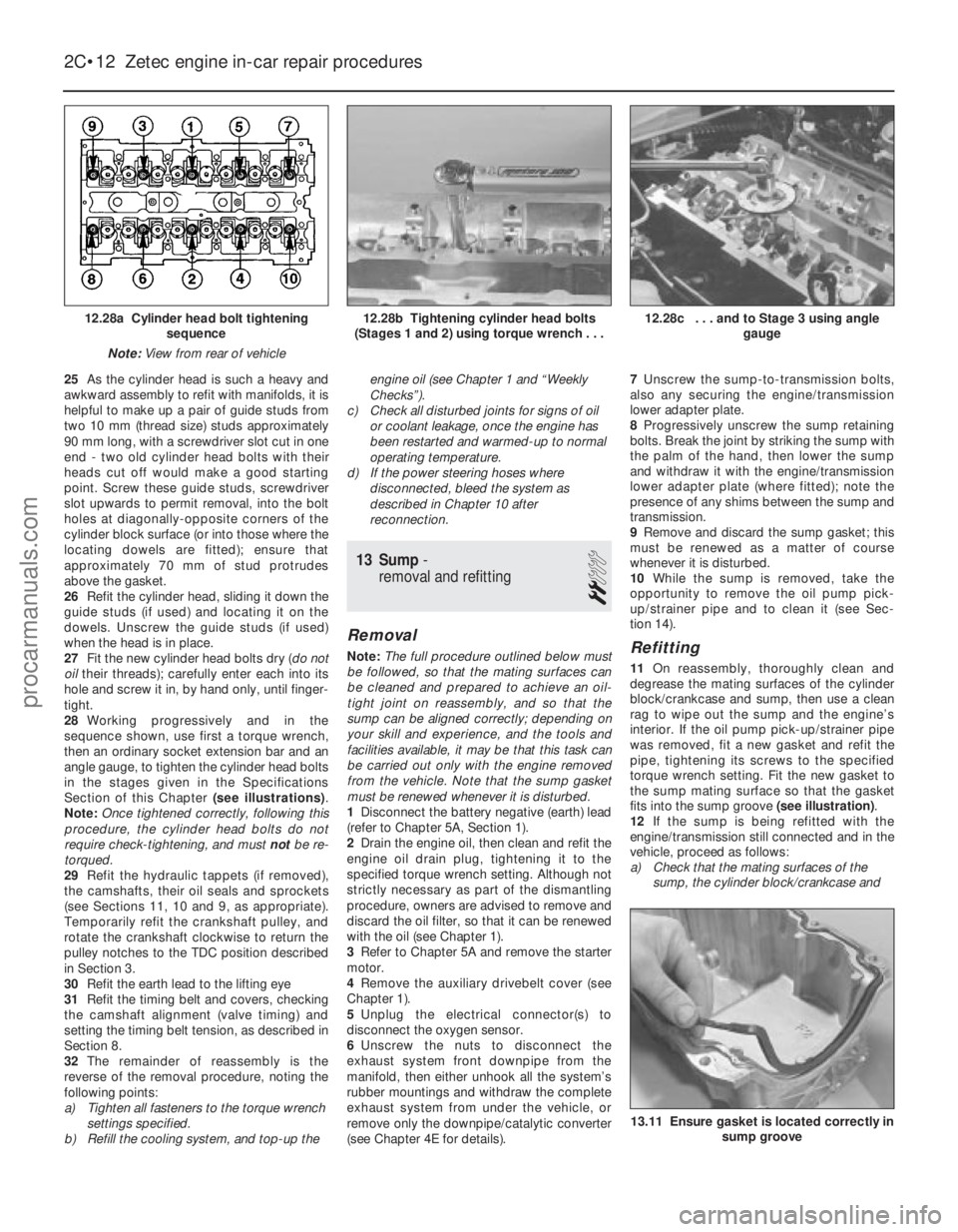
27 Fit the new cylinder head bolts dry ( do not
oil their threads); carefully enter each into its
hole and screw it in, by hand only, until finger-
tight.
28 Working progressively and in the
sequence shown, use first a torque wrench,
then an ordinary socket extension bar and an
angle gauge, to tighten the cylinder head bolts
in the stages given in the Specifications
Section of this Chapter (see illustrations).
Note: Once tightened correctly, following this
procedure, the cylinder head bolts do not
require check-tightening, and must notbe re-
torqued.
29 Refit the hydraulic tappets (if removed),
the camshafts, their oil seals and sprockets
(see Sections 11, 10 and 9, as appropriate).
Temporarily refit the crankshaft pulley, and
rotate the crankshaft clockwise to return the
pulley notches to the TDC position described
in Section 3.
30 Refit the earth lead to the lifting eye
31 Refit the timing belt and covers, checking
the camshaft alignment (valve timing) and
setting the timing belt tension, as described in
Section 8.
32 The remainder of reassembly is the
reverse of the removal procedure, noting the
following points:
a) Tighten all fasteners to the torque wrench settings specified.
b) Refill the cooling system, and top-up the engine oil (see Chapter 1 and “Weekly
Checks”).
c) Check all disturbed joints for signs of oil or coolant leakage, once the engine has
been restarted and warmed-up to normal
operating temperature.
d) If the power steering hoses where
disconnected, bleed the system as
described in Chapter 10 after
reconnection.
13 Sump -
removal and refitting
2
Removal
Note: The full procedure outlined below must
be followed, so that the mating surfaces can
be cleaned and prepared to achieve an oil-
tight joint on reassembly, and so that the
sump can be aligned correctly; depending on
your skill and experience, and the tools and
facilities available, it may be that this task can
be carried out only with the engine removed
from the vehicle. Note that the sump gasket
must be renewed whenever it is disturbed.
1 Disconnect the battery negative (earth) lead
(refer to Chapter 5A, Section 1).
2 Drain the engine oil, then clean and refit the
engine oil drain plug, tightening it to the
specified torque wrench setting. Although not
strictly necessary as part of the dismantling
procedure, owners are advised to remove and
discard the oil filter, so that it can be renewed
with the oil (see Chapter 1).
3 Refer to Chapter 5A and remove the starter
motor.
4 Remove the auxiliary drivebelt cover (see
Chapter 1).
5 Unplug the electrical connector(s) to
disconnect the oxygen sensor.
6 Unscrew the nuts to disconnect the
exhaust system front downpipe from the
manifold, then either unhook all the system’s
rubber mountings and withdraw the complete
exhaust system from under the vehicle, or
remove only the downpipe/catalytic converter
(see Chapter 4E for details). 7
Unscrew the sump-to-transmission bolts,
also any securing the engine/transmission
lower adapter plate.
8 Progressively unscrew the sump retaining
bolts. Break the joint by striking the sump with
the palm of the hand, then lower the sump
and withdraw it with the engine/transmission
lower adapter plate (where fitted); note the
presence of any shims between the sump and
transmission.
9 Remove and discard the sump gasket; this
must be renewed as a matter of course
whenever it is disturbed.
10 While the sump is removed, take the
opportunity to remove the oil pump pick-
up/strainer pipe and to clean it (see Sec-
tion 14).Refitting
11 On reassembly, thoroughly clean and
degrease the mating surfaces of the cylinder
block/crankcase and sump, then use a clean
rag to wipe out the sump and the engine’s
interior. If the oil pump pick-up/strainer pipe
was removed, fit a new gasket and refit the
pipe, tightening its screws to the specified
torque wrench setting. Fit the new gasket to
the sump mating surface so that the gasket
fits into the sump groove (see illustration).
12 If the sump is being refitted with the
engine/transmission still connected and in the
vehicle, proceed as follows:
a) Check that the mating surfaces of the sump, the cylinder block/crankcase and
2C•12 Zetec engine in-car repair procedures
13.11 Ensure gasket is located correctly in sump groove
12.28c . . . and to Stage 3 using angle gauge12.28b Tightening cylinder head bolts
(Stages 1 and 2) using torque wrench . . .12.28a Cylinder head bolt tightening sequence
Note: View from rear of vehicle
1595Ford Fiesta Remakeprocarmanuals.com
http://vnx.su
Page 69 of 296
4Check the mountings to see if the rubber is
cracked, hardened or separated from the
metal components. Sometimes, the rubber
will split right down the centre.
5 Check for relative movement between each
mounting’s brackets and the engine/
transmission or body (use a large screwdriver
or lever to attempt to move the mountings). If
movement is noted, lower the engine and
check-tighten the mounting fasteners.
Renewal
6 The engine mountings can be removed if
the weight of the engine/transmission is
supported by one of the following alternative
methods.
7 Either support the weight of the assembly
from underneath using a jack and a suitable
piece of wood between the jack saddle and
the sump or transmission (to prevent
damage), or from above by attaching a hoist
to the engine. A third method is to use a
suitable support bar with end pieces which
will engage in the water channel each side of
the bonnet lid aperture. Using an adjustable
hook and chain connected to the engine, the
weight of the engine and transmission can
then be taken from the mountings.
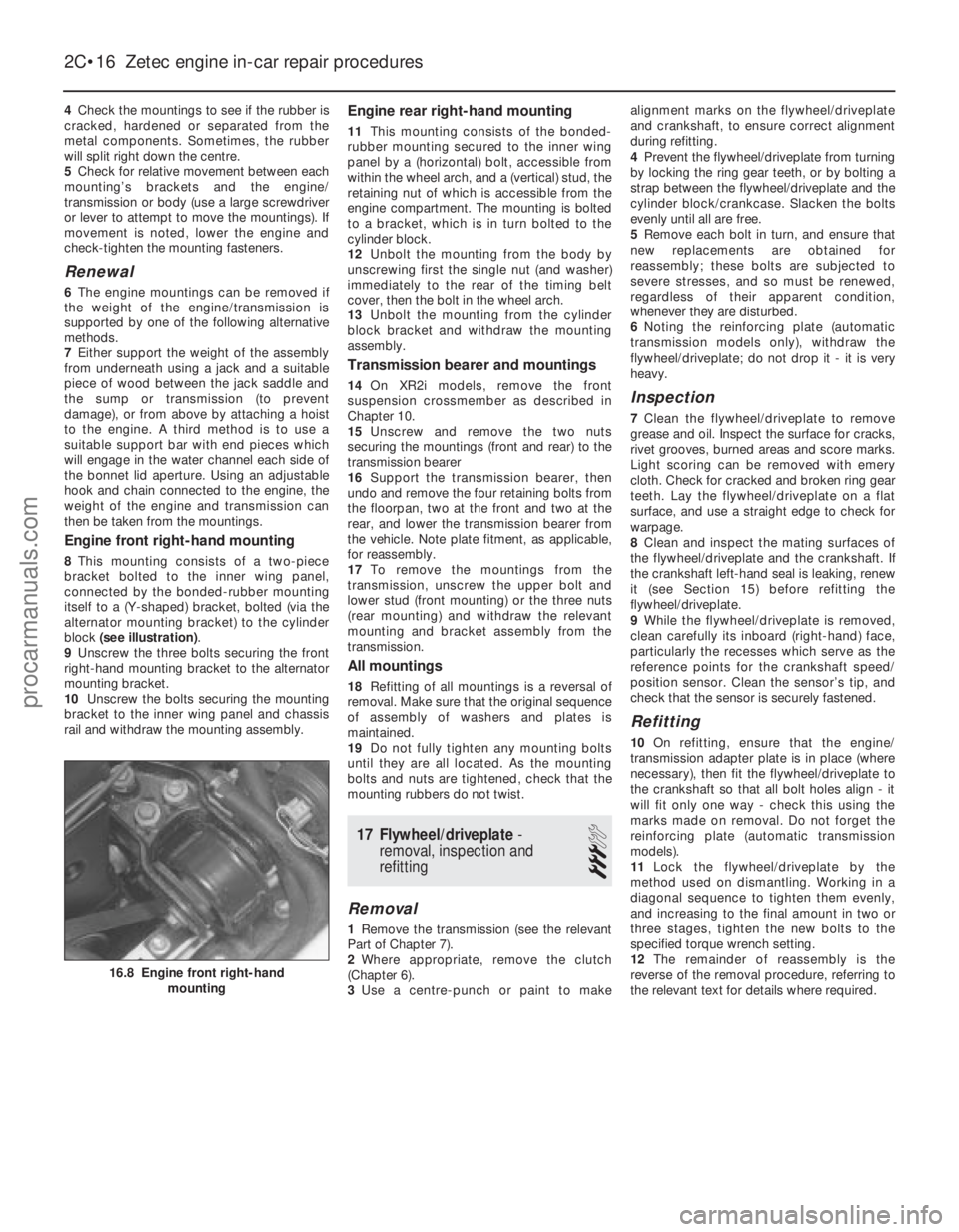
Engine front right-hand mounting
8 This mounting consists of a two-piece
bracket bolted to the inner wing panel,
connected by the bonded-rubber mounting
itself to a (Y-shaped) bracket, bolted (via the
alternator mounting bracket) to the cylinder
block (see illustration) .
9 Unscrew the three bolts securing the front
right-hand mounting bracket to the alternator
mounting bracket.
10 Unscrew the bolts securing the mounting
bracket to the inner wing panel and chassis
rail and withdraw the mounting assembly.
Engine rear right-hand mounting
11 This mounting consists of the bonded-
rubber mounting secured to the inner wing
panel by a (horizontal) bolt, accessible from
within the wheel arch, and a (vertical) stud, the
retaining nut of which is accessible from the
engine compartment. The mounting is bolted
to a bracket, which is in turn bolted to the
cylinder block.
12 Unbolt the mounting from the body by
unscrewing first the single nut (and washer)
immediately to the rear of the timing belt
cover, then the bolt in the wheel arch.
13 Unbolt the mounting from the cylinder
block bracket and withdraw the mounting
assembly.
Transmission bearer and mountings
14 On XR2i models, remove the front
suspension crossmember as described in
Chapter 10.
15 Unscrew and remove the two nuts
securing the mountings (front and rear) to the
transmission bearer
16 Support the transmission bearer, then
undo and remove the four retaining bolts from
the floorpan, two at the front and two at the
rear, and lower the transmission bearer from
the vehicle. Note plate fitment, as applicable,
for reassembly.
17 To remove the mountings from the
transmission, unscrew the upper bolt and
lower stud (front mounting) or the three nuts
(rear mounting) and withdraw the relevant
mounting and bracket assembly from the
transmission.
All mountings
18 Refitting of all mountings is a reversal of
removal. Make sure that the original sequence
of assembly of washers and plates is
maintained.
19 Do not fully tighten any mounting bolts
until they are all located. As the mounting
bolts and nuts are tightened, check that the
mounting rubbers do not twist.
17 Flywheel/driveplate -
removal, inspection and
refitting
3
Removal
1 Remove the transmission (see the relevant
Part of Chapter 7).
2 Where appropriate, remove the clutch
(Chapter 6).
3 Use a centre-punch or paint to make alignment marks on the flywheel/driveplate
and crankshaft, to ensure correct alignment
during refitting.
4
Prevent the flywheel/driveplate from turning
by locking the ring gear teeth, or by bolting a
strap between the flywheel/driveplate and the
cylinder block/crankcase. Slacken the bolts
evenly until all are free.
5 Remove each bolt in turn, and ensure that
new replacements are obtained for
reassembly; these bolts are subjected to
severe stresses, and so must be renewed,
regardless of their apparent condition,
whenever they are disturbed.
6 Noting the reinforcing plate (automatic
transmission models only), withdraw the
flywheel/driveplate; do not drop it - it is very
heavy.
Inspection
7 Clean the flywheel/driveplate to remove
grease and oil. Inspect the surface for cracks,
rivet grooves, burned areas and score marks.
Light scoring can be removed with emery
cloth. Check for cracked and broken ring gear
teeth. Lay the flywheel/driveplate on a flat
surface, and use a straight edge to check for
warpage.
8 Clean and inspect the mating surfaces of
the flywheel/driveplate and the crankshaft. If
the crankshaft left-hand seal is leaking, renew
it (see Section 15) before refitting the
flywheel/driveplate.
9 While the flywheel/driveplate is removed,
clean carefully its inboard (right-hand) face,
particularly the recesses which serve as the
reference points for the crankshaft speed/
position sensor. Clean the sensor’s tip, and
check that the sensor is securely fastened.
Refitting
10 On refitting, ensure that the engine/
transmission adapter plate is in place (where
necessary), then fit the flywheel/driveplate to
the crankshaft so that all bolt holes align - it
will fit only one way - check this using the
marks made on removal. Do not forget the
reinforcing plate (automatic transmission
models).
11 Lock the flywheel/driveplate by the
method used on dismantling. Working in a
diagonal sequence to tighten them evenly,
and increasing to the final amount in two or
three stages, tighten the new bolts to the
specified torque wrench setting.
12 The remainder of reassembly is the
reverse of the removal procedure, referring to
the relevant text for details where required.
2C•16 Zetec engine in-car repair procedures
16.8 Engine front right-hand mounting
1595Ford Fiesta Remakeprocarmanuals.com
http://vnx.su
Page 76 of 296
3Referring to Chapter 1 for details, drain the
coolant and engine oil. Refit the drain plug to
the sump on completion.
4 Remove the bonnet as described in
Chapter 11.
5 Remove the air cleaner assembly as
described in the relevant Part of Chapter 4.
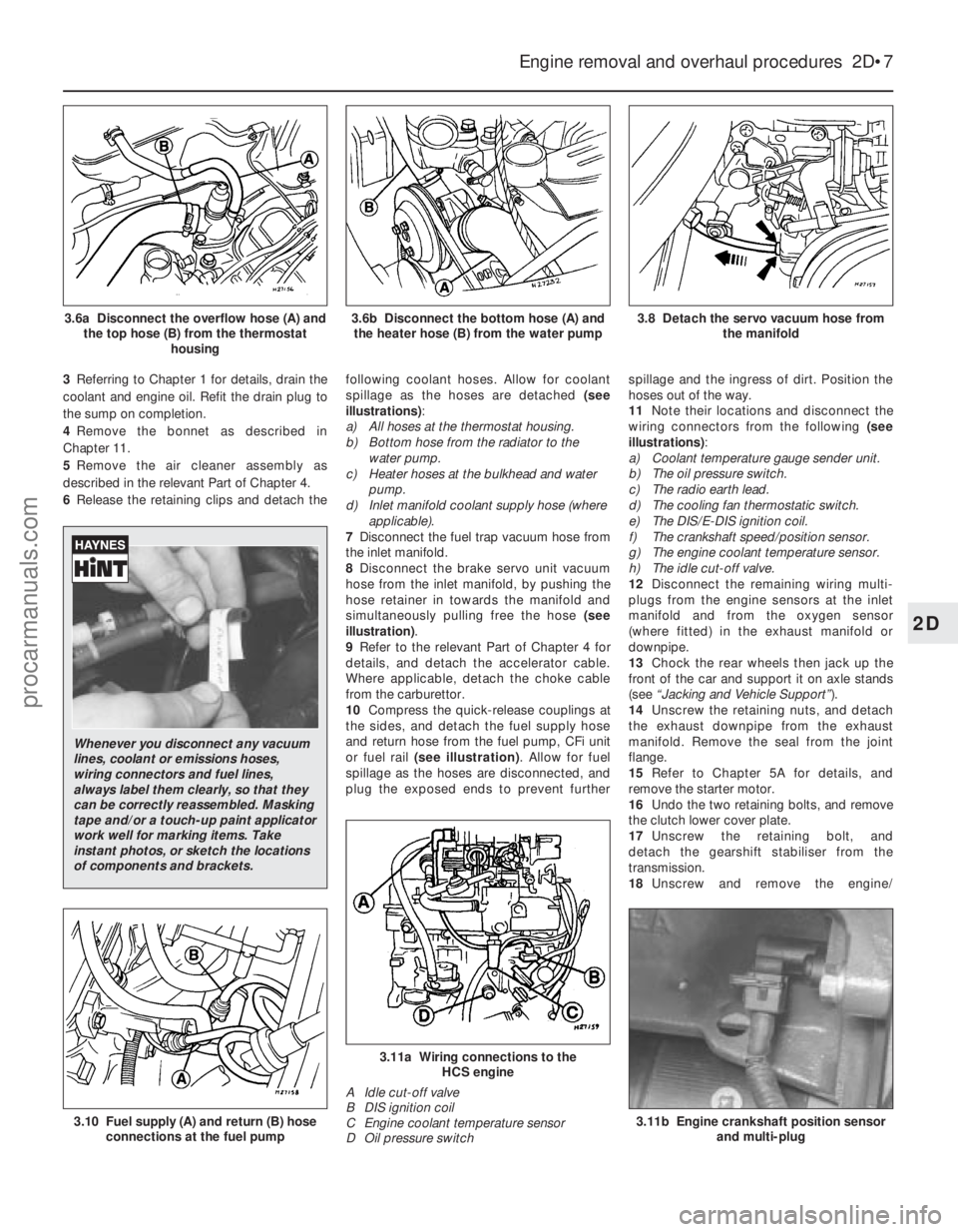
6 Release the retaining clips and detach the following coolant hoses. Allow for coolant
spillage as the hoses are detached
(see
illustrations) :
a) All hoses at the thermostat housing.
b) Bottom hose from the radiator to the
water pump.
c) Heater hoses at the bulkhead and water
pump.
d) Inlet manifold coolant supply hose (where
applicable).
7 Disconnect the fuel trap vacuum hose from
the inlet manifold.
8 Disconnect the brake servo unit vacuum
hose from the inlet manifold, by pushing the
hose retainer in towards the manifold and
simultaneously pulling free the hose (see
illustration) .
9 Refer to the relevant Part of Chapter 4 for
details, and detach the accelerator cable.
Where applicable, detach the choke cable
from the carburettor.
10 Compress the quick-release couplings at
the sides, and detach the fuel supply hose
and return hose from the fuel pump, CFi unit
or fuel rail (see illustration) . Allow for fuel
spillage as the hoses are disconnected, and
plug the exposed ends to prevent further spillage and the ingress of dirt. Position the
hoses out of the way.
11
Note their locations and disconnect the
wiring connectors from the following (see
illustrations) :
a) Coolant temperature gauge sender unit.
b) The oil pressure switch.
c) The radio earth lead.
d) The cooling fan thermostatic switch.
e) The DIS/E-DIS ignition coil.
f) The crankshaft speed/position sensor.
g) The engine coolant temperature sensor.
h) The idle cut-off valve.
12 Disconnect the remaining wiring multi-
plugs from the engine sensors at the inlet
manifold and from the oxygen sensor
(where fitted) in the exhaust manifold or
downpipe.
13 Chock the rear wheels then jack up the
front of the car and support it on axle stands
(see “Jacking and Vehicle Support” ).
14 Unscrew the retaining nuts, and detach
the exhaust downpipe from the exhaust
manifold. Remove the seal from the joint
flange.
15 Refer to Chapter 5A for details, and
remove the starter motor.
16 Undo the two retaining bolts, and remove
the clutch lower cover plate.
17 Unscrew the retaining bolt, and
detach the gearshift stabiliser from the
transmission.
18 Unscrew and remove the engine/
Engine removal and overhaul procedures 2D•7
3.8 Detach the servo vacuum hose from
the manifold3.6b Disconnect the bottom hose (A) andthe heater hose (B) from the water pump3.6a Disconnect the overflow hose (A) and the top hose (B) from the thermostat housing
3.11b Engine crankshaft position sensorand multi-plug
3.11a Wiring connections to the HCS engine
A Idle cut-off valve
B DIS ignition coil
C Engine coolant temperature sensor
D Oil pressure switch
3.10 Fuel supply (A) and return (B) hose connections at the fuel pump
2D
1595Ford Fiesta Remake
Whenever you disconnect any vacuum
lines, coolant or emissions hoses,
wiring connectors and fuel lines,
always label them clearly, so that they
can be correctly reassembled. Masking
tape and/or a touch-up paint applicator
work well for marking items. Take
instant photos, or sketch the locations
of components and brackets.
procarmanuals.com
http://vnx.su
Page 78 of 296
7Refer to the relevant Part of Chapter 4 for
details, and disconnect the accelerator cable
from the throttle linkage and support/adjuster
bracket. Where applicable, also disconnect
the choke cable. Position the cable(s) out of
the way.
8 On carburettor models, disconnect the fuel
supply hose from the fuel pump, and the
return hose from the carburettor.
9 On CFi models, detach the fuel hose at the
injector/pressure regulator unit, and the return
line, by compressing the couplings whilst
pulling the hoses free from their connections.
On EFi and SEFi models, unscrew the union
nut to detach the fuel line from the fuel rail;
release the retaining clip to detach the return
pipe from the pressure regulator. Plug the
exposed ends of the hoses and connections,
to prevent fuel spillage and the ingress of dirt.
Position the hoses out of the way.
10 Press the clamp ring inwards, and
simultaneously pull free the brake servo hose from the inlet manifold. Position it out of the
way.
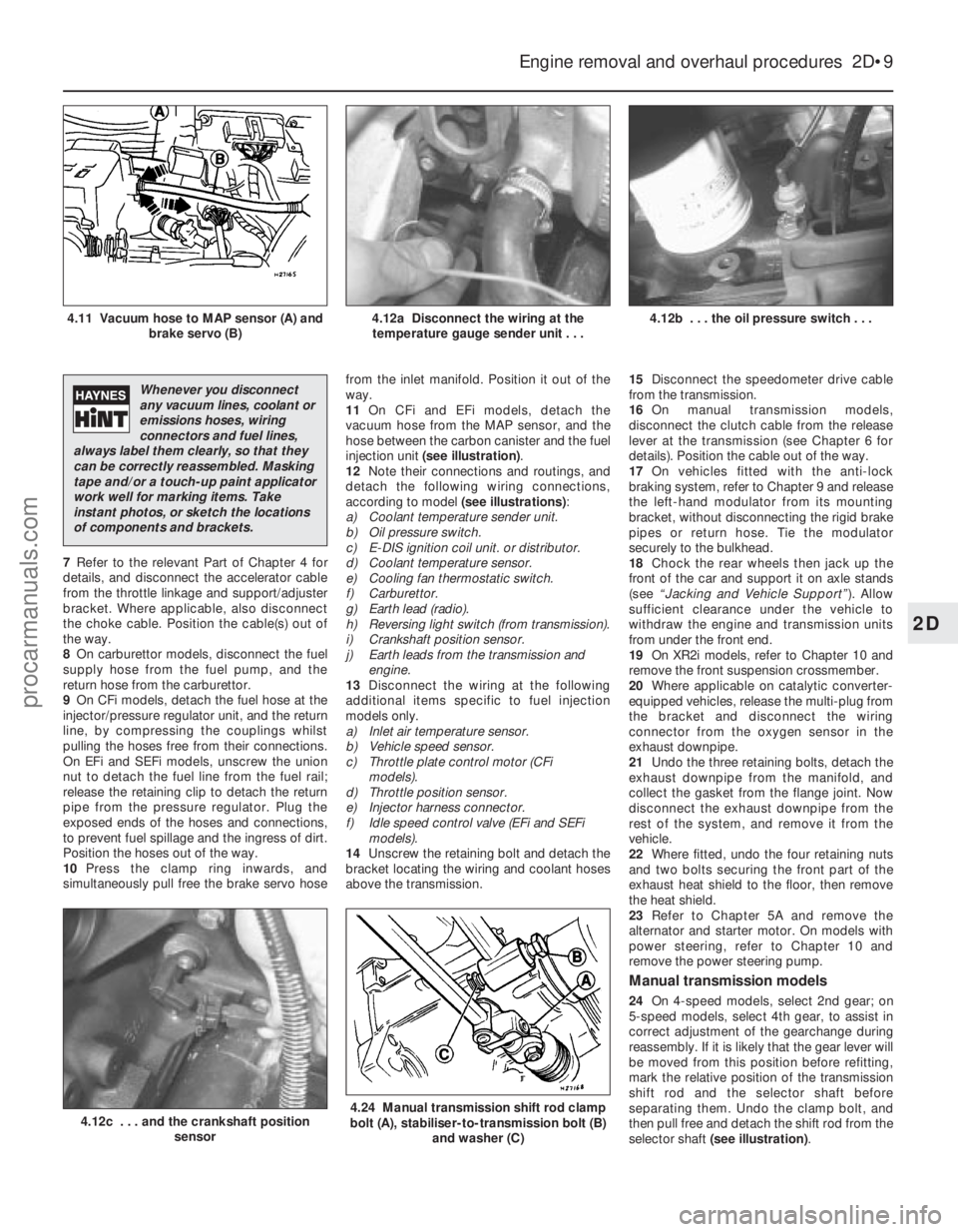
11
On CFi and EFi models, detach the
vacuum hose from the MAP sensor, and the
hose between the carbon canister and the fuel
injection unit (see illustration) .
12 Note their connections and routings, and
detach the following wiring connections,
according to model (see illustrations):
a) Coolant temperature sender unit.
b) Oil pressure switch.
c) E-DIS ignition coil unit. or distributor.
d) Coolant temperature sensor.
e) Cooling fan thermostatic switch.
f) Carburettor.
g) Earth lead (radio).
h) Reversing light switch (from transmission).
i) Crankshaft position sensor.
j) Earth leads from the transmission and engine.
13 Disconnect the wiring at the following
additional items specific to fuel injection
models only.
a) Inlet air temperature sensor.
b) Vehicle speed sensor.
c) Throttle plate control motor (CFi models).
d) Throttle position sensor.
e) Injector harness connector.
f) Idle speed control valve (EFi and SEFi models).
14 Unscrew the retaining bolt and detach the
bracket locating the wiring and coolant hoses
above the transmission. 15
Disconnect the speedometer drive cable
from the transmission.
16 On manual transmission models,
disconnect the clutch cable from the release
lever at the transmission (see Chapter 6 for
details). Position the cable out of the way.
17 On vehicles fitted with the anti-lock
braking system, refer to Chapter 9 and release
the left-hand modulator from its mounting
bracket, without disconnecting the rigid brake
pipes or return hose. Tie the modulator
securely to the bulkhead.
18 Chock the rear wheels then jack up the
front of the car and support it on axle stands
(see “Jacking and Vehicle Support” ). Allow
sufficient clearance under the vehicle to
withdraw the engine and transmission units
from under the front end.
19 On XR2i models, refer to Chapter 10 and
remove the front suspension crossmember.
20 Where applicable on catalytic converter-
equipped vehicles, release the multi-plug from
the bracket and disconnect the wiring
connector from the oxygen sensor in the
exhaust downpipe.
21 Undo the three retaining bolts, detach the
exhaust downpipe from the manifold, and
collect the gasket from the flange joint. Now
disconnect the exhaust downpipe from the
rest of the system, and remove it from the
vehicle.
22 Where fitted, undo the four retaining nuts
and two bolts securing the front part of the
exhaust heat shield to the floor, then remove
the heat shield.
23 Refer to Chapter 5A and remove the
alternator and starter motor. On models with
power steering, refer to Chapter 10 and
remove the power steering pump.
Manual transmission models
24 On 4-speed models, select 2nd gear; on
5-speed models, select 4th gear, to assist in
correct adjustment of the gearchange during
reassembly. If it is likely that the gear lever will
be moved from this position before refitting,
mark the relative position of the transmission
shift rod and the selector shaft before
separating them. Undo the clamp bolt, and
then pull free and detach the shift rod from the
selector shaft (see illustration) .
Engine removal and overhaul procedures 2D•9
4.12b . . . the oil pressure switch . . .4.12a Disconnect the wiring at the
temperature gauge sender unit . . .4.11 Vacuum hose to MAP sensor (A) and brake servo (B)
4.24 Manual transmission shift rod clamp
bolt (A), stabiliser-to-transmission bolt (B)
and washer (C)4.12c . . . and the crankshaft position sensor
2D
1595Ford Fiesta Remake
Whenever you disconnect
any vacuum lines, coolant or
emissions hoses, wiring
connectors and fuel lines,
always label them clearly, so that they
can be correctly reassembled. Masking
tape and/or a touch-up paint applicator
work well for marking items. Take
instant photos, or sketch the locations
of components and brackets.
procarmanuals.com
http://vnx.su