1989 FORD FIESTA wheel bolts
[x] Cancel search: wheel boltsPage 45 of 296
of the crankshaft sprocket, and then pull the
belt vertically upright on its right-hand run.
Keep it taut, and engage it with the teeth of
the camshaft sprocket. If the original belt is
being refitted, check that the belt’s direction
of travel is correct, and realign the belt-to-
sprocket marks made during removal, to
ensure that the exact original engagement
positions are retained. When the belt is fully
fitted on the sprockets, check that the
sprocket positions have not altered.
9Carefully manoeuvre the belt around the
tensioner, and engage its teeth with the water
pump sprocket, again ensuring that the TDC
positions of the crankshaft and camshaft
are not disturbed as the belt is finally
located.
10 Refit the lower timing belt cover, and
tighten its retaining bolts to the specified
torque setting. Refit the crankshaft pulley, and
tighten its retaining bolt to the specified
torque setting.
11 To take up belt slack, loosen off the
tensioner and move it towards the front of the
car to apply an initial tension to the belt.
Secure the tensioner in this position, then
remove the flywheel ring gear locking device.
12 Rotate the crankshaft through two full
revolutions in (the normal direction of travel),
returning to the TDC position (camshaft
sprocket-to-cylinder head). Check that the
crankshaft pulley notch is aligned with the
TDC (0) mark on the lower half of the timing
belt cover.
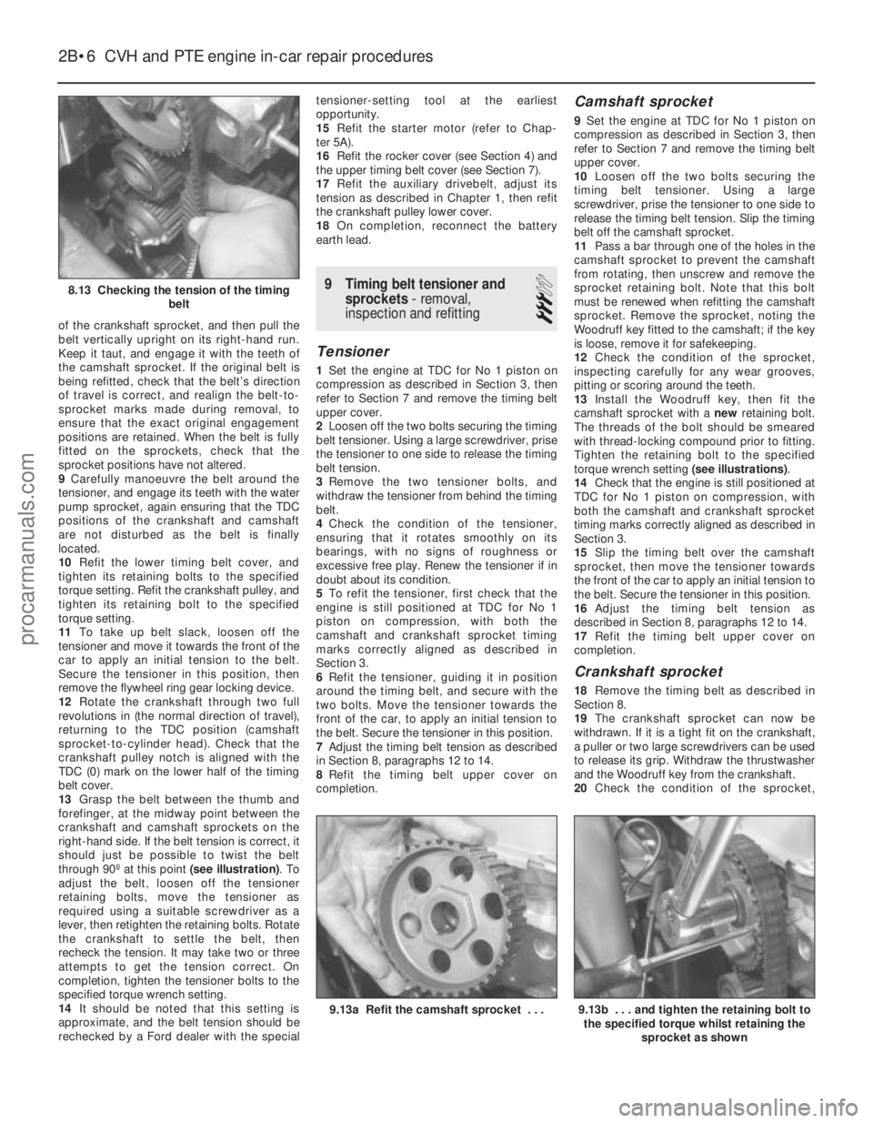
13 Grasp the belt between the thumb and
forefinger, at the midway point between the
crankshaft and camshaft sprockets on the
right-hand side. If the belt tension is correct, it
should just be possible to twist the belt
through 90º at this point (see illustration). To
adjust the belt, loosen off the tensioner
retaining bolts, move the tensioner as
required using a suitable screwdriver as a
lever, then retighten the retaining bolts. Rotate
the crankshaft to settle the belt, then
recheck the tension. It may take two or three
attempts to get the tension correct. On
completion, tighten the tensioner bolts to the
specified torque wrench setting.
14 It should be noted that this setting is
approximate, and the belt tension should be
rechecked by a Ford dealer with the special tensioner-setting tool at the earliest
opportunity.
15
Refit the starter motor (refer to Chap-
ter 5A).
16 Refit the rocker cover (see Section 4) and
the upper timing belt cover (see Section 7).
17 Refit the auxiliary drivebelt, adjust its
tension as described in Chapter 1, then refit
the crankshaft pulley lower cover.
18 On completion, reconnect the battery
earth lead.
9 Timing belt tensioner and sprockets - removal,
inspection and refitting
3
Tensioner
1 Set the engine at TDC for No 1 piston on
compression as described in Section 3, then
refer to Section 7 and remove the timing belt
upper cover.
2 Loosen off the two bolts securing the timing
belt tensioner. Using a large screwdriver, prise
the tensioner to one side to release the timing
belt tension.
3 Remove the two tensioner bolts, and
withdraw the tensioner from behind the timing
belt.
4 Check the condition of the tensioner,
ensuring that it rotates smoothly on its
bearings, with no signs of roughness or
excessive free play. Renew the tensioner if in
doubt about its condition.
5 To refit the tensioner, first check that the
engine is still positioned at TDC for No 1
piston on compression, with both the
camshaft and crankshaft sprocket timing
marks correctly aligned as described in
Section 3.
6 Refit the tensioner, guiding it in position
around the timing belt, and secure with the
two bolts. Move the tensioner towards the
front of the car, to apply an initial tension to
the belt. Secure the tensioner in this position.
7 Adjust the timing belt tension as described
in Section 8, paragraphs 12 to 14.
8 Refit the timing belt upper cover on
completion.
Camshaft sprocket
9 Set the engine at TDC for No 1 piston on
compression as described in Section 3, then
refer to Section 7 and remove the timing belt
upper cover.
10 Loosen off the two bolts securing the
timing belt tensioner. Using a large
screwdriver, prise the tensioner to one side to
release the timing belt tension. Slip the timing
belt off the camshaft sprocket.
11 Pass a bar through one of the holes in the
camshaft sprocket to prevent the camshaft
from rotating, then unscrew and remove the
sprocket retaining bolt. Note that this bolt
must be renewed when refitting the camshaft
sprocket. Remove the sprocket, noting the
Woodruff key fitted to the camshaft; if the key
is loose, remove it for safekeeping.
12 Check the condition of the sprocket,
inspecting carefully for any wear grooves,
pitting or scoring around the teeth.
13 Install the Woodruff key, then fit the
camshaft sprocket with a newretaining bolt.
The threads of the bolt should be smeared
with thread-locking compound prior to fitting.
Tighten the retaining bolt to the specified
torque wrench setting (see illustrations).
14 Check that the engine is still positioned at
TDC for No 1 piston on compression, with
both the camshaft and crankshaft sprocket
timing marks correctly aligned as described in
Section 3.
15 Slip the timing belt over the camshaft
sprocket, then move the tensioner towards
the front of the car to apply an initial tension to
the belt. Secure the tensioner in this position.
16 Adjust the timing belt tension as
described in Section 8, paragraphs 12 to 14.
17 Refit the timing belt upper cover on
completion.
Crankshaft sprocket
18 Remove the timing belt as described in
Section 8.
19 The crankshaft sprocket can now be
withdrawn. If it is a tight fit on the crankshaft,
a puller or two large screwdrivers can be used
to release its grip. Withdraw the thrustwasher
and the Woodruff key from the crankshaft.
20 Check the condition of the sprocket,
2B•6 CVH and PTE engine in-car repair procedures
9.13b . . . and tighten the retaining bolt to
the specified torque whilst retaining the
sprocket as shown9.13a Refit the camshaft sprocket . . .
8.13 Checking the tension of the timing belt
1595Ford Fiesta Remakeprocarmanuals.com
http://vnx.su
Page 48 of 296
23Refer to the procedure in Section 9 when
refitting the camshaft sprocket.
24 Refit and tension the timing belt as
described in Section 8.
25 Lubricate the hydraulic tappets with
hypoid oil before refitting them into their
original locations in the cylinder head.
26 Lubricate and refit the rocker arms and
guides in their original sequence, use new
nuts and tighten them to the specified torque
setting. It is essential, before each rocker arm
is installed and its nut tightened, that the
respective cam follower is positioned at its
lowest point (in contact with the cam base
circle). Turn the cam (using the crankshaft
pulley bolt) as necessary to achieve this.
27 Refit the rocker cover as described in
Section 4.
28 Refit the remaining components with
reference to the relevant Sections in this
Chapter or elsewhere in the manual.
29 On completion, reconnect the battery
negative lead.
12 Cylinder head -
removal and refitting
4
Removal
Note: The following procedure describes
removal and refitting of the cylinder head
complete with inlet and exhaust manifolds. If
wished, the manifolds may be removed first,
as described in the relevant Part of Chapter 4,
and the cylinder head then removed on its
own.
1 On fuel-injected engines, depressurise the
fuel system as described in Chapter 4B or 4C.
2 Disconnect the battery negative (earth) lead
(refer to Chapter 5A, Section 1).
3 Refer to Chapter 1 and drain the cooling
system. 4
Remove the rocker cover as described in
Section 4.
5 Disconnect the accelerator and choke
cables as applicable (refer to the relevant Part
of Chapter 4).
6 Loosen off the retaining clips and
disconnect the upper coolant hose, the
expansion tank hose and the heater hose
from the thermostat housing. Also disconnect
the heater hose from the inlet manifold.
7 On CFi models, disconnect the heated
coolant hose from the injector unit.
8 On EFi and SEFi models, disconnect the
following (see illustration) :
a) The MAP sensor vacuum hose from the inlet manifold upper section (EFi models).
b) The carbon canister solenoid valve
vacuum hose from the inlet manifold
upper section.
c) The oil trap vacuum hose at the “T” piece
connector.
d) The brake servo vacuum hose from the
inlet manifold upper section by pressing
in the clamp ring and simultaneously
pulling the hose free from the connection.
e) The coolant hose from the injector
intermediate flange and at the thermostat
housing.
9 Disconnect the following fuel supply/return
hoses. Plug the hoses and connections, to
prevent fuel spillage and the possible ingress
of dirt.
a) On carburettor models, disconnect the fuel supply hose from the pump and the
return hose from the carburettor.
b) On CFi models, pull free and detach the
fuel return hose from the injection unit
and the supply hose at the connector. c) On EFi and SEFi models, detach the fuel
supply hose from the fuel rail or at the
quick-release coupling (where fitted).
Disconnect the return line from the fuel
pressure regulator or at the quick-release
coupling.
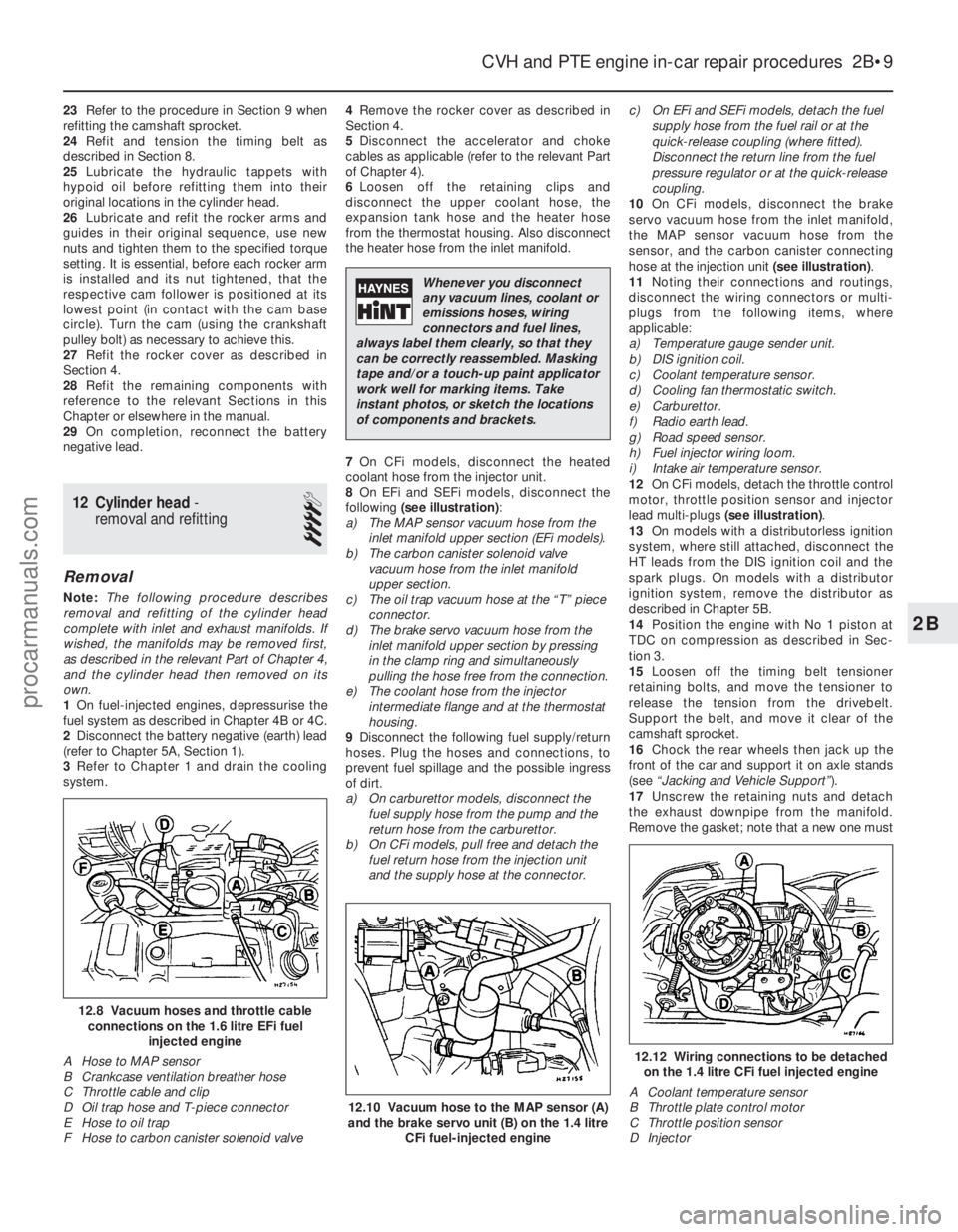
10 On CFi models, disconnect the brake
servo vacuum hose from the inlet manifold,
the MAP sensor vacuum hose from the
sensor, and the carbon canister connecting
hose at the injection unit (see illustration).
11 Noting their connections and routings,
disconnect the wiring connectors or multi-
plugs from the following items, where
applicable:
a) Temperature gauge sender unit.
b) DIS ignition coil.
c) Coolant temperature sensor.
d) Cooling fan thermostatic switch.
e) Carburettor.
f) Radio earth lead.
g) Road speed sensor.
h) Fuel injector wiring loom.
i) Intake air temperature sensor.
12 On CFi models, detach the throttle control
motor, throttle position sensor and injector
lead multi-plugs (see illustration) .
13 On models with a distributorless ignition
system, where still attached, disconnect the
HT leads from the DIS ignition coil and the
spark plugs. On models with a distributor
ignition system, remove the distributor as
described in Chapter 5B.
14 Position the engine with No 1 piston at
TDC on compression as described in Sec-
tion 3.
15 Loosen off the timing belt tensioner
retaining bolts, and move the tensioner to
release the tension from the drivebelt.
Support the belt, and move it clear of the
camshaft sprocket.
16 Chock the rear wheels then jack up the
front of the car and support it on axle stands
(see “Jacking and Vehicle Support” ).
17 Unscrew the retaining nuts and detach
the exhaust downpipe from the manifold.
Remove the gasket; note that a new one must
CVH and PTE engine in-car repair procedures 2B•9
12.12 Wiring connections to be detached on the 1.4 litre CFi fuel injected engine
A Coolant temperature sensor
B Throttle plate control motor
C Throttle position sensor
D Injector
12.10 Vacuum hose to the MAP sensor (A)
and the brake servo unit (B) on the 1.4 litre
CFi fuel-injected engine
12.8 Vacuum hoses and throttle cableconnections on the 1.6 litre EFi fuel injected engine
A Hose to MAP sensor
B Crankcase ventilation breather hose
C Throttle cable and clip
D Oil trap hose and T-piece connector
E Hose to oil trap
F Hose to carbon canister solenoid valve
2B
1595Ford Fiesta Remake
Whenever you disconnect
any vacuum lines, coolant or
emissions hoses, wiring
connectors and fuel lines,
always label them clearly, so that they
can be correctly reassembled. Masking
tape and/or a touch-up paint applicator
work well for marking items. Take
instant photos, or sketch the locations
of components and brackets.
procarmanuals.com
http://vnx.su
Page 49 of 296
be fitted on reassembly. Tie the downpipe up
to support it.
18Before it is released and removed, the
cylinder head must first have cooled down to
room temperature (about 20ºC).
19 Unscrew the cylinder head retaining bolts
progressively in the reverse order to that
shown for tightening (see illustration 12.28).
The cylinder head bolts must be discarded
and new bolts obtained for refitting the
cylinder head.
20 Remove the cylinder head complete with
its manifolds. If necessary, grip the manifolds
and rock it free from the location dowels on
the top face of the cylinder block. Do not
attempt to tap it sideways or lever between
the head and the block top face.
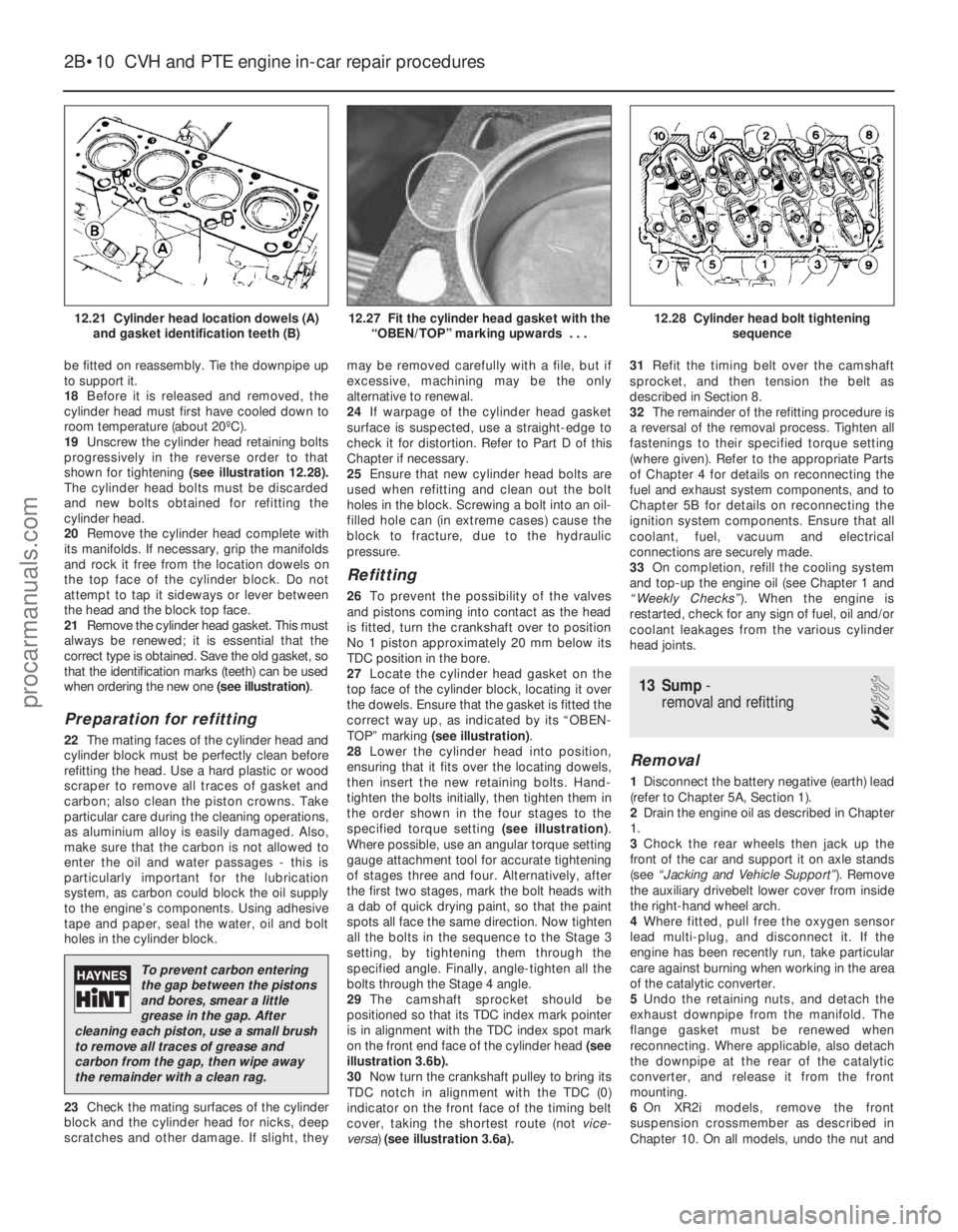
21 Remove the cylinder head gasket. This must
always be renewed; it is essential that the
correct type is obtained. Save the old gasket, so
that the identification marks (teeth) can be used
when ordering the new one (see illustration).
Preparation for refitting
22The mating faces of the cylinder head and
cylinder block must be perfectly clean before
refitting the head. Use a hard plastic or wood
scraper to remove all traces of gasket and
carbon; also clean the piston crowns. Take
particular care during the cleaning operations,
as aluminium alloy is easily damaged. Also,
make sure that the carbon is not allowed to
enter the oil and water passages - this is
particularly important for the lubrication
system, as carbon could block the oil supply
to the engine’s components. Using adhesive
tape and paper, seal the water, oil and bolt
holes in the cylinder block.
23 Check the mating surfaces of the cylinder
block and the cylinder head for nicks, deep
scratches and other damage. If slight, they may be removed carefully with a file, but if
excessive, machining may be the only
alternative to renewal.
24
If warpage of the cylinder head gasket
surface is suspected, use a straight-edge to
check it for distortion. Refer to Part D of this
Chapter if necessary.
25 Ensure that new cylinder head bolts are
used when refitting and clean out the bolt
holes in the block. Screwing a bolt into an oil-
filled hole can (in extreme cases) cause the
block to fracture, due to the hydraulic
pressure.
Refitting
26 To prevent the possibility of the valves
and pistons coming into contact as the head
is fitted, turn the crankshaft over to position
No 1 piston approximately 20 mm below its
TDC position in the bore.
27 Locate the cylinder head gasket on the
top face of the cylinder block, locating it over
the dowels. Ensure that the gasket is fitted the
correct way up, as indicated by its “OBEN-
TOP” marking (see illustration) .
28 Lower the cylinder head into position,
ensuring that it fits over the locating dowels,
then insert the new retaining bolts. Hand-
tighten the bolts initially, then tighten them in
the order shown in the four stages to the
specified torque setting (see illustration).
Where possible, use an angular torque setting
gauge attachment tool for accurate tightening
of stages three and four. Alternatively, after
the first two stages, mark the bolt heads with
a dab of quick drying paint, so that the paint
spots all face the same direction. Now tighten
all the bolts in the sequence to the Stage 3
setting, by tightening them through the
specified angle. Finally, angle-tighten all the
bolts through the Stage 4 angle.
29 The camshaft sprocket should be
positioned so that its TDC index mark pointer
is in alignment with the TDC index spot mark
on the front end face of the cylinder head (see
illustration 3.6b).
30 Now turn the crankshaft pulley to bring its
TDC notch in alignment with the TDC (0)
indicator on the front face of the timing belt
cover, taking the shortest route (not vice-
versa) (see illustration 3.6a). 31
Refit the timing belt over the camshaft
sprocket, and then tension the belt as
described in Section 8.
32 The remainder of the refitting procedure is
a reversal of the removal process. Tighten all
fastenings to their specified torque setting
(where given). Refer to the appropriate Parts
of Chapter 4 for details on reconnecting the
fuel and exhaust system components, and to
Chapter 5B for details on reconnecting the
ignition system components. Ensure that all
coolant, fuel, vacuum and electrical
connections are securely made.
33 On completion, refill the cooling system
and top-up the engine oil (see Chapter 1 and
“Weekly Checks” ). When the engine is
restarted, check for any sign of fuel, oil and/or
coolant leakages from the various cylinder
head joints.
13 Sump -
removal and refitting
2
Removal
1 Disconnect the battery negative (earth) lead
(refer to Chapter 5A, Section 1).
2 Drain the engine oil as described in Chapter
1.
3 Chock the rear wheels then jack up the
front of the car and support it on axle stands
(see “Jacking and Vehicle Support” ). Remove
the auxiliary drivebelt lower cover from inside
the right-hand wheel arch.
4 Where fitted, pull free the oxygen sensor
lead multi-plug, and disconnect it. If the
engine has been recently run, take particular
care against burning when working in the area
of the catalytic converter.
5 Undo the retaining nuts, and detach the
exhaust downpipe from the manifold. The
flange gasket must be renewed when
reconnecting. Where applicable, also detach
the downpipe at the rear of the catalytic
converter, and release it from the front
mounting.
6 On XR2i models, remove the front
suspension crossmember as described in
Chapter 10. On all models, undo the nut and
2B•10 CVH and PTE engine in-car repair procedures
12.28 Cylinder head bolt tightening
sequence12.27 Fit the cylinder head gasket with the“OBEN/TOP” marking upwards . . .12.21 Cylinder head location dowels (A)and gasket identification teeth (B)
1595Ford Fiesta Remake
To prevent carbon entering
the gap between the pistons
and bores, smear a little
grease in the gap. After
cleaning each piston, use a small brush
to remove all traces of grease and
carbon from the gap, then wipe away
the remainder with a clean rag.
procarmanuals.com
http://vnx.su
Page 51 of 296
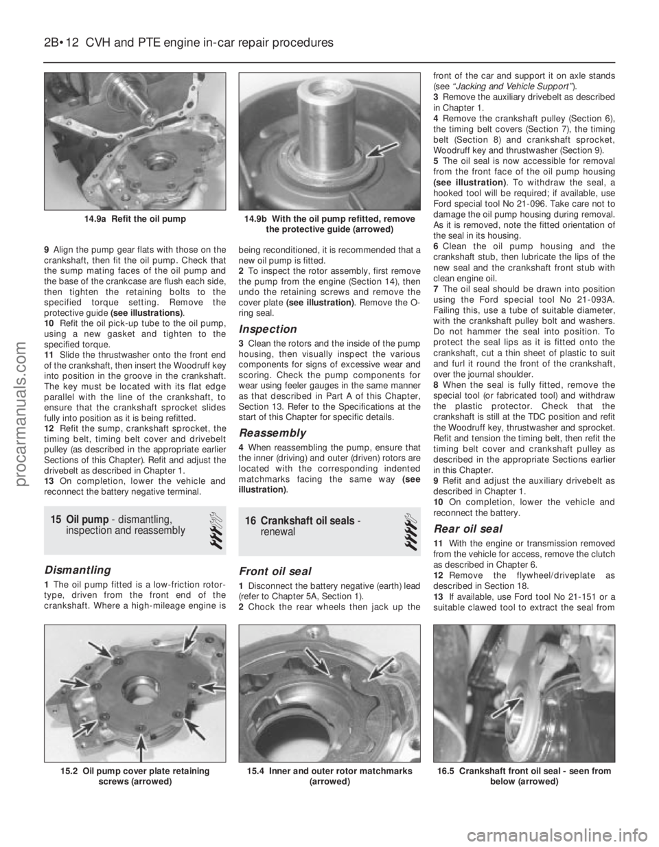
9Align the pump gear flats with those on the
crankshaft, then fit the oil pump. Check that
the sump mating faces of the oil pump and
the base of the crankcase are flush each side,
then tighten the retaining bolts to the
specified torque setting. Remove the
protective guide (see illustrations) .
10 Refit the oil pick-up tube to the oil pump,
using a new gasket and tighten to the
specified torque.
11 Slide the thrustwasher onto the front end
of the crankshaft, then insert the Woodruff key
into position in the groove in the crankshaft.
The key must be located with its flat edge
parallel with the line of the crankshaft, to
ensure that the crankshaft sprocket slides
fully into position as it is being refitted.
12 Refit the sump, crankshaft sprocket, the
timing belt, timing belt cover and drivebelt
pulley (as described in the appropriate earlier
Sections of this Chapter). Refit and adjust the
drivebelt as described in Chapter 1.
13 On completion, lower the vehicle and
reconnect the battery negative terminal.
15 Oil pump - dismantling,
inspection and reassembly
3
Dismantling
1 The oil pump fitted is a low-friction rotor-
type, driven from the front end of the
crankshaft. Where a high-mileage engine is being reconditioned, it is recommended that a
new oil pump is fitted.
2
To inspect the rotor assembly, first remove
the pump from the engine (Section 14), then
undo the retaining screws and remove the
cover plate (see illustration) . Remove the O-
ring seal.
Inspection
3 Clean the rotors and the inside of the pump
housing, then visually inspect the various
components for signs of excessive wear and
scoring. Check the pump components for
wear using feeler gauges in the same manner
as that described in Part A of this Chapter,
Section 13. Refer to the Specifications at the
start of this Chapter for specific details.
Reassembly
4 When reassembling the pump, ensure that
the inner (driving) and outer (driven) rotors are
located with the corresponding indented
matchmarks facing the same way (see
illustration) .
16Crankshaft oil seals -
renewal
4
Front oil seal
1 Disconnect the battery negative (earth) lead
(refer to Chapter 5A, Section 1).
2 Chock the rear wheels then jack up the front of the car and support it on axle stands
(see
“Jacking and Vehicle Support” ).
3 Remove the auxiliary drivebelt as described
in Chapter 1.
4 Remove the crankshaft pulley (Section 6),
the timing belt covers (Section 7), the timing
belt (Section 8) and crankshaft sprocket,
Woodruff key and thrustwasher (Section 9).
5 The oil seal is now accessible for removal
from the front face of the oil pump housing
(see illustration) . To withdraw the seal, a
hooked tool will be required; if available, use
Ford special tool No 21-096. Take care not to
damage the oil pump housing during removal.
As it is removed, note the fitted orientation of
the seal in its housing.
6 Clean the oil pump housing and the
crankshaft stub, then lubricate the lips of the
new seal and the crankshaft front stub with
clean engine oil.
7 The oil seal should be drawn into position
using the Ford special tool No 21-093A.
Failing this, use a tube of suitable diameter,
with the crankshaft pulley bolt and washers.
Do not hammer the seal into position. To
protect the seal lips as it is fitted onto the
crankshaft, cut a thin sheet of plastic to suit
and furl it round the front of the crankshaft,
over the journal shoulder.
8 When the seal is fully fitted, remove the
special tool (or fabricated tool) and withdraw
the plastic protector. Check that the
crankshaft is still at the TDC position and refit
the Woodruff key, thrustwasher and sprocket.
Refit and tension the timing belt, then refit the
timing belt cover and crankshaft pulley as
described in the appropriate Sections earlier
in this Chapter.
9 Refit and adjust the auxiliary drivebelt as
described in Chapter 1.
10 On completion, lower the vehicle and
reconnect the battery.
Rear oil seal
11 With the engine or transmission removed
from the vehicle for access, remove the clutch
as described in Chapter 6.
12 Remove the flywheel/driveplate as
described in Section 18.
13 If available, use Ford tool No 21-151 or a
suitable clawed tool to extract the seal from
2B•12 CVH and PTE engine in-car repair procedures
16.5 Crankshaft front oil seal - seen from
below (arrowed)15.4 Inner and outer rotor matchmarks (arrowed)15.2 Oil pump cover plate retainingscrews (arrowed)
14.9b With the oil pump refitted, removethe protective guide (arrowed)14.9a Refit the oil pump
1595Ford Fiesta Remakeprocarmanuals.com
http://vnx.su
Page 52 of 296
its housing. If the seal housing is removed
from the rear face of the engine, the seal can
be removed as described in paragraph 18. As
it is removed, note the direction of fitting, and
take care not to damage the seal housing as
the seal is extracted.
14Clean the seal housing, the crankshaft
rear flange face, and the flywheel/driveplate
mating surfaces.
15 One of two possible methods may be
used to insert the new oil seal, depending on
the tools available.
16 If Ford special service tool No 21-095 is
available, lubricate the seal lips of the seal and
its running face on the crankshaft with clean
engine oil. Position the seal (correctly
orientated) into the special tool, then draw the
seal into the housing using two
flywheel/driveplate securing bolts so that the
seal is against the stop.
17 If the correct Ford service tool is not
available, it will be necessary to remove the oil
seal carrier housing. To do this, first remove
the sump as described in Section 13, then
unscrew the seal housing retaining bolts and
remove the housing from the rear face of the
crankcase.
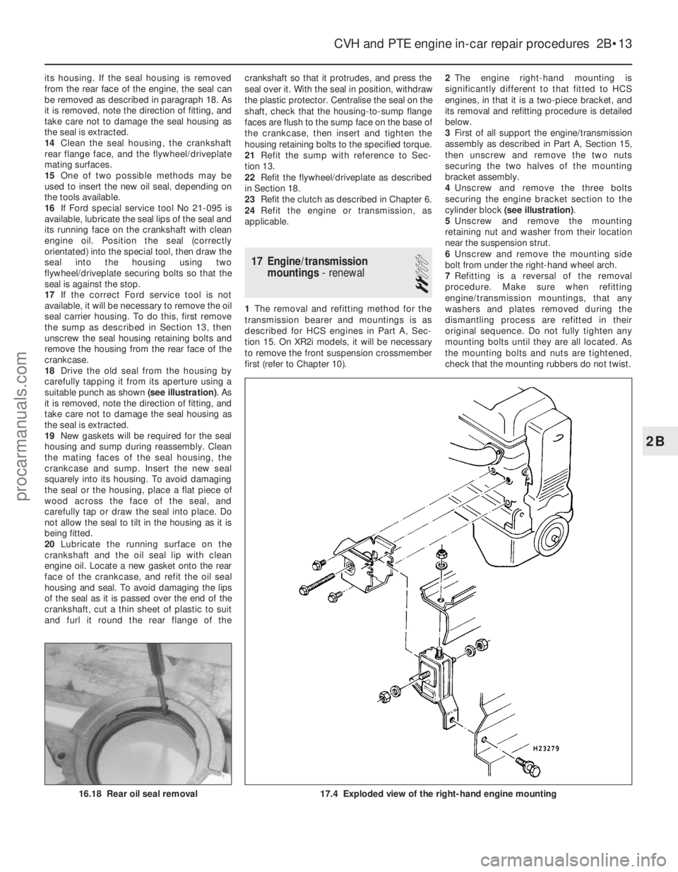
18 Drive the old seal from the housing by
carefully tapping it from its aperture using a
suitable punch as shown (see illustration). As
it is removed, note the direction of fitting, and
take care not to damage the seal housing as
the seal is extracted.
19 New gaskets will be required for the seal
housing and sump during reassembly. Clean
the mating faces of the seal housing, the
crankcase and sump. Insert the new seal
squarely into its housing. To avoid damaging
the seal or the housing, place a flat piece of
wood across the face of the seal, and
carefully tap or draw the seal into place. Do
not allow the seal to tilt in the housing as it is
being fitted.
20 Lubricate the running surface on the
crankshaft and the oil seal lip with clean
engine oil. Locate a new gasket onto the rear
face of the crankcase, and refit the oil seal
housing and seal. To avoid damaging the lips
of the seal as it is passed over the end of the
crankshaft, cut a thin sheet of plastic to suit
and furl it round the rear flange of the crankshaft so that it protrudes, and press the
seal over it. With the seal in position, withdraw
the plastic protector. Centralise the seal on the
shaft, check that the housing-to-sump flange
faces are flush to the sump face on the base of
the crankcase, then insert and tighten the
housing retaining bolts to the specified torque.
21
Refit the sump with reference to Sec-
tion 13.
22 Refit the flywheel/driveplate as described
in Section 18.
23 Refit the clutch as described in Chapter 6.
24 Refit the engine or transmission, as
applicable.
17 Engine/transmission mountings - renewal
2
1The removal and refitting method for the
transmission bearer and mountings is as
described for HCS engines in Part A, Sec-
tion 15. On XR2i models, it will be necessary
to remove the front suspension crossmember
first (refer to Chapter 10). 2
The engine right-hand mounting is
significantly different to that fitted to HCS
engines, in that it is a two-piece bracket, and
its removal and refitting procedure is detailed
below.
3 First of all support the engine/transmission
assembly as described in Part A, Section 15,
then unscrew and remove the two nuts
securing the two halves of the mounting
bracket assembly.
4 Unscrew and remove the three bolts
securing the engine bracket section to the
cylinder block (see illustration) .
5 Unscrew and remove the mounting
retaining nut and washer from their location
near the suspension strut.
6 Unscrew and remove the mounting side
bolt from under the right-hand wheel arch.
7 Refitting is a reversal of the removal
procedure. Make sure when refitting
engine/transmission mountings, that any
washers and plates removed during the
dismantling process are refitted in their
original sequence. Do not fully tighten any
mounting bolts until they are all located. As
the mounting bolts and nuts are tightened,
check that the mounting rubbers do not twist.
CVH and PTE engine in-car repair procedures 2B•13
17.4 Exploded view of the right-hand engine mounting16.18 Rear oil seal removal
2B
1595Ford Fiesta Remakeprocarmanuals.com
http://vnx.su
Page 53 of 296
18 Flywheel/driveplate-
removal, inspection and
refitting
3
Removal
1 Access to the flywheel (manual transmission)
or driveplate (automatic transmission) is gained
by first removing the transmission (Chapter 7A
or B). On manual transmission models, remove
the clutch (Chapter 6).
2 Unscrew and remove the six
flywheel/driveplate retaining bolts, and
carefully withdraw the flywheel/driveplate from the rear face of the crankshaft. Take care
not to drop the flywheel, as it is heavy. Note
that the retaining bolts must be renewed when
refitting.
Inspection
3
The inspection procedures for the
flywheel/driveplate are the same as those
described for the HCS engine in Part A of this
Chapter, but note that the grinding procedures
do not apply to automatic transmission
models (the driveplate cannot be reground).
Refitting
4 Check that the mating faces of the flywheel/driveplate and crankshaft are clean
before refitting.
5
Smear the new retaining bolt threads with
thread-locking compound. Fit the
flywheel/driveplate into position on the rear end
face of the crankshaft. Check that all of the bolt
holes in the flywheel/driveplate are in exact
alignment with the corresponding bolt holes in
the crankshaft, then insert the newbolts and
tighten them in a progressive sequence to the
specified torque wrench setting.
6 Refit the clutch (manual transmission
models) as described in Chapter 6.
7 Refit the transmission (according to type) as
described in Chapter 7A or B.
2B•14 CVH and PTE engine in-car repair procedures
1595Ford Fiesta Remakeprocarmanuals.com
http://vnx.su
Page 55 of 296
Torque wrench settingsNmlbf ft
Cylinder head cover bolts: Stage 1 . . . . . . . . . . . . . . . . . . . . . . . . . . . . . . . . . . . .\
. . . . . . . . . . . . 2 1.5
Stage 2 . . . . . . . . . . . . . . . . . . . . . . . . . . . . . . . . . . . .\
. . . . . . . . . . . . 7 5
Camshaft sprocket bolts . . . . . . . . . . . . . . . . . . . . . . . . . . . . . . . . . . . .\
6850
Camshaft bearing cap bolts: Stage 1 . . . . . . . . . . . . . . . . . . . . . . . . . . . . . . . . . . . .\
. . . . . . . . . . . . 9 7
Stage 2 . . . . . . . . . . . . . . . . . . . . . . . . . . . . . . . . . . . .\
. . . . . . . . . . . . 1914
Cylinder head bolts: Stage 1 . . . . . . . . . . . . . . . . . . . . . . . . . . . . . . . . . . . .\
. . . . . . . . . . . . 2418
Stage 2 . . . . . . . . . . . . . . . . . . . . . . . . . . . . . . . . . . . .\
. . . . . . . . . . . . 4533
Stage 3 . . . . . . . . . . . . . . . . . . . . . . . . . . . . . . . . . . . .\
. . . . . . . . . . . . Angle-tighten a further 105º
Timing belt cover fasteners: Upper-to-middle (outer) cover bolts . . . . . . . . . . . . . . . . . . . . . . . . . . 4 3
Cover-to-cylinder head or block bolts . . . . . . . . . . . . . . . . . . . . . . . . 7 5
Cover studs-to-cylinder head or block . . . . . . . . . . . . . . . . . . . . . . . . 9 7
Timing belt tensioner bolt . . . . . . . . . . . . . . . . . . . . . . . . . . . . . . . . . . . .\
3828
Timing belt tensioner backplate locating peg . . . . . . . . . . . . . . . . . . . . . 9 7
Timing belt tensioner spring retaining pin . . . . . . . . . . . . . . . . . . . . . . . 9 7
Timing belt guide pulley bolts . . . . . . . . . . . . . . . . . . . . . . . . . . . . . . . . . 3828
Water pump pulley bolts . . . . . . . . . . . . . . . . . . . . . . . . . . . . . . . . . . . .\
. 9 7
Auxiliary drivebelt idler pulley . . . . . . . . . . . . . . . . . . . . . . . . . . . . . . . . . 4735
Front engine lifting eye bolt . . . . . . . . . . . . . . . . . . . . . . . . . . . . . . . . . . 1612
Exhaust manifold heat shield bolts: Shield-to-cylinder head . . . . . . . . . . . . . . . . . . . . . . . . . . . . . . . . . . . 7 5
Shield/dipstick tube . . . . . . . . . . . . . . . . . . . . . . . . . . . . . . . . . . . .\
. . 9 7
Shield/coolant pipe-to-manifold . . . . . . . . . . . . . . . . . . . . . . . . . . . . . 2317
Crankshaft pulley bolt . . . . . . . . . . . . . . . . . . . . . . . . . . . . . . . . . . . .\
. . . 115 85
Oil pump-to-cylinder block bolts . . . . . . . . . . . . . . . . . . . . . . . . . . . . . . 107
Oil pick-up pipe-to-pump screws . . . . . . . . . . . . . . . . . . . . . . . . . . . . . . 107
Oil baffle/pump pick-up pipe nuts . . . . . . . . . . . . . . . . . . . . . . . . . . . . . 1914
Oil filter adapter-to-pump . . . . . . . . . . . . . . . . . . . . . . . . . . . . . . . . . . . .\
2216
Oil pressure warning light switch . . . . . . . . . . . . . . . . . . . . . . . . . . . . . . 2720
Sump bolts . . . . . . . . . . . . . . . . . . . . . . . . . . . . . . . . . . . .\
. . . . . . . . . . . 2015
Coolant pipe-to-sump bolt . . . . . . . . . . . . . . . . . . . . . . . . . . . . . . . . . . . 9 7
Flywheel/driveplate bolts . . . . . . . . . . . . . . . . . . . . . . . . . . . . . . . . . . . .\
110 81
Crankshaft left-hand oil seal carrier bolts . . . . . . . . . . . . . . . . . . . . . . . . 2216
Engine mountings: Engine front right-hand mounting:Alternator mounting bracket-to-cylinder block bolts . . . . . . . . . . . 41 to 58 30 to 43
Mounting bracket-to-alternator mounting bracket bolts . . . . . . . . Not available Not available
Mounting through-bolt . . . . . . . . . . . . . . . . . . . . . . . . . . . . . . . . . . Not available Not available
Outer bracket-to-mounting bolts . . . . . . . . . . . . . . . . . . . . . . . . . . 58 to 79 43 to 58
Inner bracket-to-body bolts . . . . . . . . . . . . . . . . . . . . . . . . . . . . . . 58 to 79 43 to 58
Outer bracket-to-body bolts . . . . . . . . . . . . . . . . . . . . . . . . . . . . . . 58 to 79 43 to 58
Engine rear right-hand mounting: . . . . . . . . . . . . . . . . . . . . . . . . . . . . Bracket-to-cylinder block bolts . . . . . . . . . . . . . . . . . . . . . . . . . . . 76 to 104 56 to 77
Mounting-to-(cylinder block) bracket bolts . . . . . . . . . . . . . . . . . . . 71 to 98 52 to 72
Mounting-to-body bolt and nut . . . . . . . . . . . . . . . . . . . . . . . . . . . . 102 to 138 75 to 102
Transmission mounting fasteners . . . . . . . . . . . . . . . . . . . . . . . . . . . . Refer to Chapter 7A or 7B
Note: Refer to Part D of this Chapter for remaining torque wrench settings.
2C•2 Zetec engine in-car repair procedures
1595Ford Fiesta Remake
1 General information
How to use this Chapter
This Part of Chapter 2 is devoted to repair
procedures possible while the engine is still
installed in the vehicle, and includes only the
Specifications relevant to those procedures.
Similar information concerning the 1.3 litre
HCS engines, and the 1.4 and 1.6 litre CVH
and PTE engines, will be found in Parts A
and B of this Chapter respectively. Since these procedures are based on the
assumption that the engine is installed in the
vehicle, if the engine has been removed from
the vehicle and mounted on a stand, some
of the preliminary dismantling steps outlined
will not apply.
Information concerning engine/transmission
removal and refitting, and engine overhaul, can
be found in Part D of this Chapter, which also
includes the Specifications relevant to those
procedures.
Engine description
The Zetec engine, (formerly Zeta), is of
sixteen-valve, double overhead camshaft (DOHC), four-cylinder, in-line type, mounted
transversely at the front of the vehicle, with
the transmission on its left-hand end.
Apart from the plastic timing belt covers
and the cast-iron cylinder block/crankcase, all
major engine castings are of aluminium alloy. The crankshaft runs in five main bearings,
the centre main bearing’s upper half
incorporating thrustwashers to control
crankshaft endfloat. The connecting rods
rotate on horizontally-split bearing shells at
their big-ends. The pistons are attached to the
connecting rods by gudgeon pins which are
an interference fit in the connecting rod small-
end eyes. The aluminium alloy pistons are
procarmanuals.com
http://vnx.su
Page 57 of 296
clamp brackets and disconnect the pipe joint
union over the top of the cylinder head cover.
Place absorbent rags beneath the union as it
is disconnected to soak up escaping fluid and
plug the open unions to prevent dirt entry and
further fluid loss. Move the pipe(s) clear just
sufficiently to allow removal of the cylinder
head cover.
5Remove the timing belt upper cover (see
Section 7).
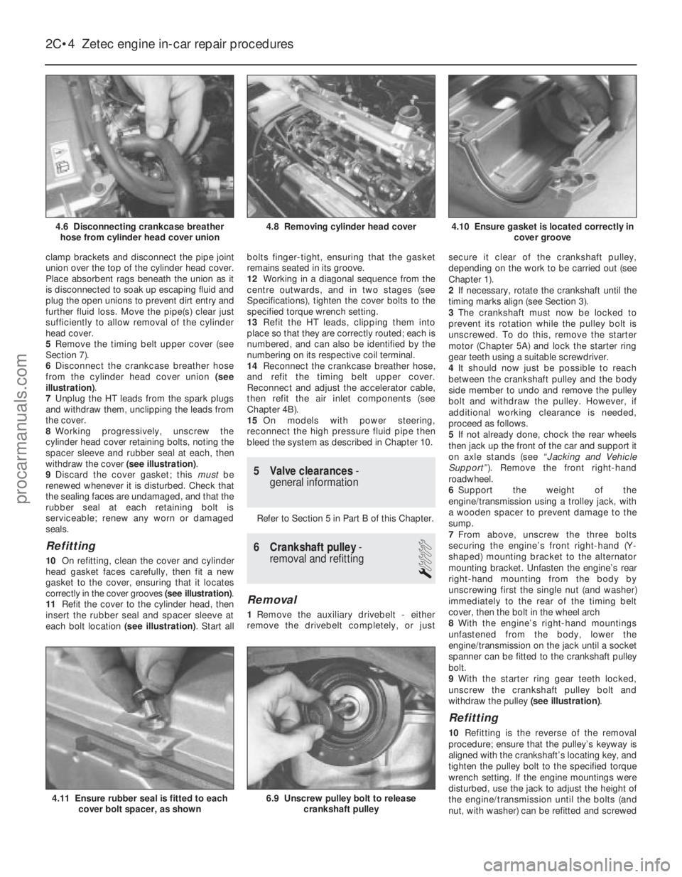
6 Disconnect the crankcase breather hose
from the cylinder head cover union (see
illustration) .
7 Unplug the HT leads from the spark plugs
and withdraw them, unclipping the leads from
the cover.
8 Working progressively, unscrew the
cylinder head cover retaining bolts, noting the
spacer sleeve and rubber seal at each, then
withdraw the cover (see illustration).
9 Discard the cover gasket; this mustbe
renewed whenever it is disturbed. Check that
the sealing faces are undamaged, and that the
rubber seal at each retaining bolt is
serviceable; renew any worn or damaged
seals.
Refitting
10 On refitting, clean the cover and cylinder
head gasket faces carefully, then fit a new
gasket to the cover, ensuring that it locates
correctly in the cover grooves (see illustration).
11 Refit the cover to the cylinder head, then
insert the rubber seal and spacer sleeve at
each bolt location (see illustration). Start allbolts finger-tight, ensuring that the gasket
remains seated in its groove.
12
Working in a diagonal sequence from the
centre outwards, and in two stages (see
Specifications), tighten the cover bolts to the
specified torque wrench setting.
13 Refit the HT leads, clipping them into
place so that they are correctly routed; each is
numbered, and can also be identified by the
numbering on its respective coil terminal.
14 Reconnect the crankcase breather hose,
and refit the timing belt upper cover.
Reconnect and adjust the accelerator cable,
then refit the air inlet components (see
Chapter 4B).
15 On models with power steering,
reconnect the high pressure fluid pipe then
bleed the system as described in Chapter 10.
5 Valve clearances -
general information
Refer to Section 5 in Part B of this Chapter.
6 Crankshaft pulley -
removal and refitting
1
Removal
1 Remove the auxiliary drivebelt - either
remove the drivebelt completely, or just secure it clear of the crankshaft pulley,
depending on the work to be carried out (see
Chapter 1).
2
If necessary, rotate the crankshaft until the
timing marks align (see Section 3).
3 The crankshaft must now be locked to
prevent its rotation while the pulley bolt is
unscrewed. To do this, remove the starter
motor (Chapter 5A) and lock the starter ring
gear teeth using a suitable screwdriver.
4 It should now just be possible to reach
between the crankshaft pulley and the body
side member to undo and remove the pulley
bolt and withdraw the pulley. However, if
additional working clearance is needed,
proceed as follows.
5 If not already done, chock the rear wheels
then jack up the front of the car and support it
on axle stands (see “Jacking and Vehicle
Support” ). Remove the front right-hand
roadwheel.
6 Support the weight of the
engine/transmission using a trolley jack, with
a wooden spacer to prevent damage to the
sump.
7 From above, unscrew the three bolts
securing the engine’s front right-hand (Y-
shaped) mounting bracket to the alternator
mounting bracket. Unfasten the engine’s rear
right-hand mounting from the body by
unscrewing first the single nut (and washer)
immediately to the rear of the timing belt
cover, then the bolt in the wheel arch
8 With the engine’s right-hand mountings
unfastened from the body, lower the
engine/transmission on the jack until a socket
spanner can be fitted to the crankshaft pulley
bolt.
9 With the starter ring gear teeth locked,
unscrew the crankshaft pulley bolt and
withdraw the pulley (see illustration).
Refitting
10Refitting is the reverse of the removal
procedure; ensure that the pulley’s keyway is
aligned with the crankshaft’s locating key, and
tighten the pulley bolt to the specified torque
wrench setting. If the engine mountings were
disturbed, use the jack to adjust the height of
the engine/transmission until the bolts (and
nut, with washer) can be refitted and screwed
2C•4 Zetec engine in-car repair procedures
6.9 Unscrew pulley bolt to release
crankshaft pulley4.11 Ensure rubber seal is fitted to eachcover bolt spacer, as shown
4.10 Ensure gasket is located correctly in cover groove4.8 Removing cylinder head cover
1595Ford Fiesta Remake
4.6 Disconnecting crankcase breather
hose from cylinder head cover unionprocarmanuals.com
http://vnx.su