1989 FORD FIESTA wheel bolts
[x] Cancel search: wheel boltsPage 236 of 296
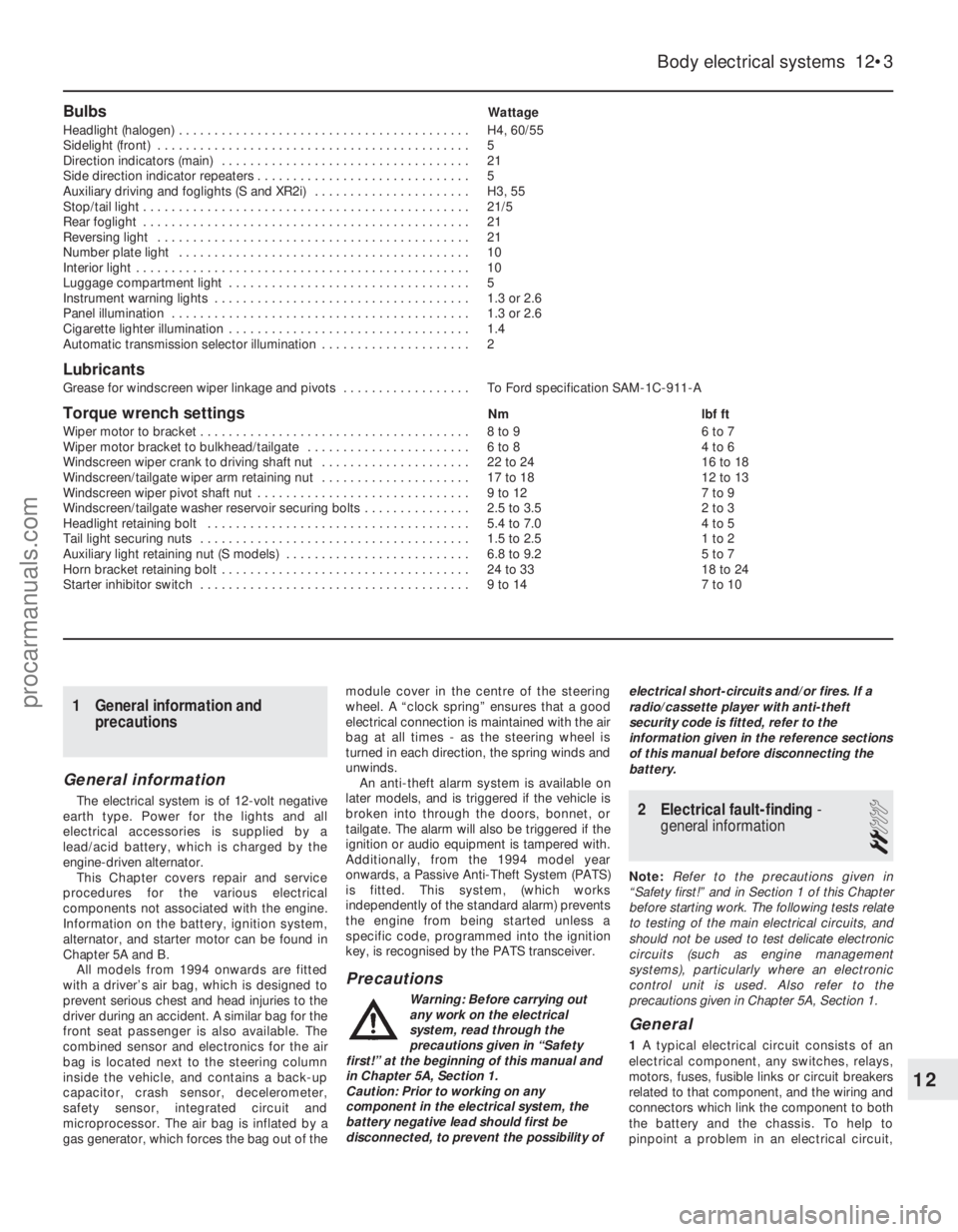
BulbsWattage
Headlight (halogen) . . . . . . . . . . . . . . . . . . . . . . . . . . . . . . . . . . . .\
. . . . . H4, 60/55
Sidelight (front) . . . . . . . . . . . . . . . . . . . . . . . . . . . . . . . . . . . .\
. . . . . . . . 5
Direction indicators (main) . . . . . . . . . . . . . . . . . . . . . . . . . . . . . . . . . . . 21
Side direction indicator repeaters . . . . . . . . . . . . . . . . . . . . . . . . . . . . . . 5
Auxiliary driving and foglights (S and XR2i) . . . . . . . . . . . . . . . . . . . . . . H3, 55
Stop/tail light . . . . . . . . . . . . . . . . . . . . . . . . . . . . . . . . . . . .\
. . . . . . . . . . 21/5
Rear foglight . . . . . . . . . . . . . . . . . . . . . . . . . . . . . . . . . . . .\
. . . . . . . . . . 21
Reversing light . . . . . . . . . . . . . . . . . . . . . . . . . . . . . . . . . . . .\
. . . . . . . . 21
Number plate light . . . . . . . . . . . . . . . . . . . . . . . . . . . . . . . . . . . .\
. . . . . 10
Interior light . . . . . . . . . . . . . . . . . . . . . . . . . . . . . . . . . . . .\
. . . . . . . . . . . 10
Luggage compartment light . . . . . . . . . . . . . . . . . . . . . . . . . . . . . . . . . . 5
Instrument warning lights . . . . . . . . . . . . . . . . . . . . . . . . . . . . . . . . . . . .\
1.3 or 2.6
Panel illumination . . . . . . . . . . . . . . . . . . . . . . . . . . . . . . . . . . . .\
. . . . . . 1.3 or 2.6
Cigarette lighter illumination . . . . . . . . . . . . . . . . . . . . . . . . . . . . . . . . . . 1.4
Automatic transmission selector illumination . . . . . . . . . . . . . . . . . . . . . 2
Lubricants
Grease for windscreen wiper linkage and pivots . . . . . . . . . . . . . . . . . . To Ford specification SAM-1C-911-A
Torque wrench settingsNm lbf ft
Wiper motor to bracket . . . . . . . . . . . . . . . . . . . . . . . . . . . . . . . . . . . .\
. . 8 to 9 6 to 7
Wiper motor bracket to bulkhead/tailgate . . . . . . . . . . . . . . . . . . . . . . . 6 to 8 4 to 6
Windscreen wiper crank to driving shaft nut . . . . . . . . . . . . . . . . . . . . . 22 to 24 16 to 18
Windscreen/tailgate wiper arm retaining nut . . . . . . . . . . . . . . . . . . . . . 17 to 18 12 to 13
Windscreen wiper pivot shaft nut . . . . . . . . . . . . . . . . . . . . . . . . . . . . . . 9 to 12 7 to 9
Windscreen/tailgate washer reservoir securing bolts . . . . . . . . . . . . . . . 2.5 to 3.5 2 to 3
Headlight retaining bolt . . . . . . . . . . . . . . . . . . . . . . . . . . . . . . . . . . . .\
. 5.4 to 7.0 4 to 5
Tail light securing nuts . . . . . . . . . . . . . . . . . . . . . . . . . . . . . . . . . . . .\
. . 1.5 to 2.5 1 to 2
Auxiliary light retaining nut (S models) . . . . . . . . . . . . . . . . . . . . . . . . . . 6.8 to 9.2 5 to 7
Horn bracket retaining bolt . . . . . . . . . . . . . . . . . . . . . . . . . . . . . . . . . . . 24 to 33 18 to 24
Starter inhibitor switch . . . . . . . . . . . . . . . . . . . . . . . . . . . . . . . . . . . .\
. . 9 to 14 7 to 10
Body electrical systems 12•3
12
1595Ford Fiesta Remake
1 General information and
precautions
General information
The electrical system is of 12-volt negative
earth type. Power for the lights and all
electrical accessories is supplied by a
lead/acid battery, which is charged by the
engine-driven alternator.
This Chapter covers repair and service
procedures for the various electrical
components not associated with the engine.
Information on the battery, ignition system,
alternator, and starter motor can be found in
Chapter 5A and B.
All models from 1994 onwards are fitted
with a driver’s air bag, which is designed to
prevent serious chest and head injuries to the
driver during an accident. A similar bag for the
front seat passenger is also available. The
combined sensor and electronics for the air
bag is located next to the steering column
inside the vehicle, and contains a back-up
capacitor, crash sensor, decelerometer,
safety sensor, integrated circuit and
microprocessor. The air bag is inflated by a
gas generator, which forces the bag out of the module cover in the centre of the steering
wheel. A “clock spring” ensures that a good
electrical connection is maintained with the air
bag at all times - as the steering wheel is
turned in each direction, the spring winds and
unwinds.
An anti-theft alarm system is available on
later models, and is triggered if the vehicle is
broken into through the doors, bonnet, or
tailgate. The alarm will also be triggered if the
ignition or audio equipment is tampered with.
Additionally, from the 1994 model year
onwards, a Passive Anti-Theft System (PATS)
is fitted. This system, (which works
independently of the standard alarm) prevents
the engine from being started unless a
specific code, programmed into the ignition
key, is recognised by the PATS transceiver.
Precautions
Warning: Before carrying out
any work on the electrical
system, read through the
precautions given in “Safety
first!” at the beginning of this manual and
in Chapter 5A, Section 1.
Caution: Prior to working on any
component in the electrical system, the
battery negative lead should first be
disconnected, to prevent the possibility of electrical short-circuits and/or fires. If a
radio/cassette player with anti-theft
security code is fitted, refer to the
information given in the reference sections
of this manual before disconnecting the
battery.
2 Electrical fault-finding
-
general information
2
Note: Refer to the precautions given in
“Safety first!” and in Section 1 of this Chapter
before starting work. The following tests relate
to testing of the main electrical circuits, and
should not be used to test delicate electronic
circuits (such as engine management
systems), particularly where an electronic
control unit is used. Also refer to the
precautions given in Chapter 5A, Section 1.
General
1 A typical electrical circuit consists of an
electrical component, any switches, relays,
motors, fuses, fusible links or circuit breakers
related to that component, and the wiring and
connectors which link the component to both
the battery and the chassis. To help to
pinpoint a problem in an electrical circuit,
procarmanuals.com
http://vnx.su
Page 247 of 296
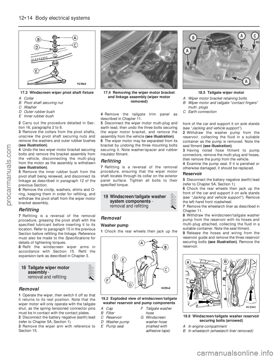
2Carry out the procedure detailed in Sec-
tion 16, paragraphs 2 to 6.
3 Remove the collars from the pivot shafts,
unscrew the pivot shaft securing nuts and
remove the washers and outer rubber bushes
(see illustration) .
4 Undo the two wiper motor bracket securing
bolts and remove the bracket assembly from
the vehicle, disconnecting the multi-plug
from the motor as the assembly is withdrawn
(see illustration) .
5 Remove the inner rubber bush from the
pivot shaft being renewed, and disconnect its
linkage as described in paragraph 12 of the
previous Section.
6 Remove the circlip, washers, shims and O-
ring, keeping them in order for refitting, and
withdraw the pivot shaft from the wiper motor
bracket assembly.
Refitting
7 Refitting is a reversal of the removal
procedure, greasing the pivot shaft with the
specified lubricant before inserting it to its
location. Refer to paragraph 15 in the previous
Section before refitting the linkage. Reference
must also be made to the Specificationsfor
details of tightening torques.
8 Refit the windscreen wiper arms in
accordance with Section 15. Refit the
expansion tank as described in Chapter 3.
18 Tailgate wiper motor assembly -
removal and refitting
1
Removal
1 Operate the wiper, then switch it off so that
it returns to its rest position. Note that the
wiper motor will only operate with the tailgate
shut, as the spring-tensioned connector pins
must be in contact with the contact plates.
2 Disconnect the battery negative (earth) lead
(refer to Chapter 5A, Section 1).
3 Remove the wiper arm with reference to
Section 15. 4
Remove the tailgate trim panel as
described in Chapter 11.
5 Disconnect the wiper motor multi-plug and
earth lead, then undo the three bolts securing
the wiper motor bracket, and remove the
assembly from the vehicle (see illustration).
6 The wiper motor may be separated from its
bracket by undoing the three mounting bolts
securing it. Note washer/spacer and rubber
insulator fitment.
Refitting
7 Refitting is a reversal of the removal
procedure, ensuring that the wiper motor
shaft locates through its collar on the exterior
panel surface. Tighten all bolts to their
specified torque.
19 Windscreen/tailgate washer system components -
removal and refitting
1
Removal
Washer pump
1 Chock the rear wheels then jack up the front of the car and support it on axle stands
(see
“Jacking and vehicle support” ).
2 Withdraw the washer pump from the
reservoir, collecting the fluid in a suitable
container as the pump is removed. Note the
seal fitment (see illustration) .
3 Having noted hose fitment to pump
connectors, remove the multi-plug and hoses,
then remove the pump from the vehicle.
4 Examine the pump seal. If it is perished or
otherwise damaged, it should be replaced.
Reservoir
5 Disconnect the battery negative (earth) lead
(refer to Chapter 5A, Section 1).
6 Chock the rear wheels then jack up the
front of the car and support it on axle stands
(see “Jacking and vehicle support” ). Remove
the left-hand front roadwheel.
7 Remove the wheelarch liner as described in
Chapter 11.
8 Withdraw the windscreen/tailgate washer
pump from the reservoir with its hoses and
multi-plug attached, collecting the fluid in a
suitable container. Note the seal fitment.
9 Release the hoses and wiring from the
reservoir guide and remove the three reservoir
securing bolts (see illustration) . Remove the
reservoir.
12•14 Body electrical systems
19.9 Windscreen/tailgate washer reservoir
securing bolts (arrowed)
A In engine compartment
B In wheelarch (wheelarch liner removed)
19.2 Exploded view of windscreen/tailgate washer reservoir and pump components
A Cap
B Filter
C Reservoir
D Washer pump
E Pump seal F Tailgate washer
hose
G Windscreen
washer hose
(marked with
adhesive tape)
18.5 Tailgate wiper motor
A Wiper motor bracket retaining bolts
B Wiper motor and tailgate “contact fingers” multi- plugs
C Earth connection17.4 Removing the wiper motor bracket and linkage assembly (wiper motor removed)17.3 Windscreen wiper pivot shaft fixture
A Collar
B Pivot shaft securing nut
C Washer
D Outer rubber bush
E Inner rubber bush
1595Ford Fiesta Remakeprocarmanuals.com
http://vnx.su
Page 248 of 296
Windscreen washer jets and hoses
10Disconnect the battery negative (earth)
lead (refer to Chapter 5A, Section 1).
11 With the bonnet raised and supported on
its stay, release the fasteners securing its
insulation panel (where fitted). Remove the
insulation panel.
12 Carefully press in the retaining lugs on the
washer jets using a flat-bladed screwdriver,
then raise the washer jets from the exterior
surface of the bonnet and separate them from
their hoses
13 The windscreen washer jet hose may have
been fitted with a one-way (non-return) valve.
If this is the case, the main hose run sections
can be removed from either side of the valve
as required.
14 Chock the rear wheels then jack up the
front of the car and support it on axle stands
(see “Jacking and vehicle support” ).
15 Disconnect the windscreen washer hose
(marked with adhesive tape) from the washer
pump (see illustration 19.2) . Withdraw the
hose from the reservoir guide, and into the
engine compartment.
16 Release the hose from its clips in the
engine compartment, including the bonnet
hinge clip, release the hose grommet from the
bonnet (where fitted) and withdraw the hoses
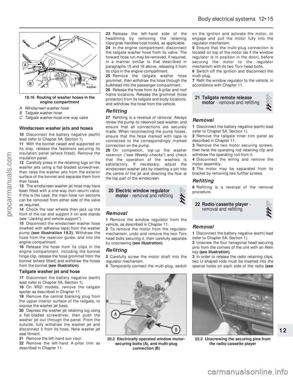
from the bonnet (see illustration) .
Tailgate washer jet and hose
17Disconnect the battery negative (earth)
lead (refer to Chapter 5A, Section 1).
18 On XR2i models, remove the tailgate
spoiler as described in Chapter 11.
19 Remove the central blanking plug from
the upper interior surface of the tailgate, to
expose the washer jet base.
20 Depress the washer jet retaining lug using
a flat-bladed screwdriver, then push the
washer jet out through the panel. From the
outside, fully withdraw the washer jet and
disconnect it from its hose. Note washer jet
seal fitment.
21 Remove the left-hand sun visor.
22 Remove the left-hand A-pillar trim as
described in Chapter 11. 23
Release the left-hand side of the
headlining by removing the retaining
clips/grab handles/coat hooks, as applicable.
24 In the engine compartment, disconnect
the tailgate washer hose from its valve. The
forward hose run may be removed, if required,
in a manner similar to that described in
paragraphs 15 and 16 above, releasing it from
its clips in the engine compartment.
25 Remove the tailgate washer hose
grommet, then withdraw the hose through the
bulkhead into the passenger compartment.
26 Release the hose from its A-pillar and roof
frame locations. Release the grommet (hose
protector) from its tailgate and body locations,
and withdraw the hose from the vehicle.
Refitting
27 Refitting is a reversal of removal. Always
renew the pump-to-reservoir seal washer, and
ensure that all connections are securely
made. When reconnecting the pump hoses,
ensure that the hose marked with tape is
connected to the correspondingly marked
connection on the pump.
28 On completion, top-up the washer
reservoir ( “see Weekly checks” ) and check
that the operation of the washers is
satisfactory. If necessary, adjust the
windscreen washer jets by inserting a pin into
the centre of the jet and directing the flow at
the top part of the windscreen.
20 Electric window regulator motor - removal and refitting
3
Removal
1Remove the window regulator from the
vehicle, as described in Chapter 11.
2 To remove the motor from the regulator
mechanism, undo and remove the two Torx
head bolts securing it, then carefully separate
by unscrewing (see illustration) .
Refitting
3Carefully screw the motor shaft into the
regulator mechanism.
4 Temporarily connect the multi-plug, switch on the ignition and activate the motor, to
engage and pull the motor fully into the
regulator mechanism.
5
Ensure that the multi-plug connection is
located on top of the motor (as if the window
regulator is in position in the door), before
securing the motor to the regulator
mechanism with its two Torx-head bolts.
6 Switch off the ignition and disconnect the
multi-plug.
7 Refit the window regulator to the vehicle, in
accordance with Chapter 11.
21 Tailgate remote release motor - removal and refitting
2
Removal
1Disconnect the battery negative (earth) lead
(refer to Chapter 5A, Section 1).
2 Remove the tailgate inner trim panel as
described in Chapter 11.
3 Remove the two motor securing screws,
then twist the operating rod retaining clip and
withdraw the operating rod from it.
4 Disconnect the wiring and remove the
motor assembly.
5 The motor may be separated from its
bracket by removing two further screws.
Refitting
6 Refitting is a reversal of the removal
procedure.
22 Radio/cassette player -
removal and refitting
3
Removal
1 Disconnect the battery negative (earth) lead
(refer to Chapter 5A, Section 1).
2 Unscrew the four hexagonal head securing
pins from the corners of the unit with an Allen
key (see illustration) .
3 In order to release the radio retaining clips,
two U-shaped rods must be inserted into the
special holes on each side of the radio (see
Body electrical systems 12•15
19.16 Routing of washer hoses in the
engine compartment
A Windscreen washer hose
B Tailgate washer hose
C Tailgate washer hose one-way valve
22.2 Unscrewing the securing pins from the radio/cassette player20.2 Electrically operated window motor-securing bolts (A), and multi-plug
connection (B)
12
1595Ford Fiesta Remakeprocarmanuals.com
http://vnx.su
Page 250 of 296
27 Anti-theft systems-
general information
Anti-theft alarm system
1 This system provides an added form of
vehicle security. When the system is
activated, the alarm will sound if the vehicle is
broken into through any one of the doors, the
bonnet, or tailgate. The alarm will also be
triggered if the ignition system is turned on or
the radio/cassette disconnected whilst the
system is activated.
2 This system is activated/de-activated
whenever one of the front doors is
locked/unlocked by the key. The system
operates on all doors, the bonnet and tailgate
whenever each door is individually locked (or,
in the case of central locking, when the central
locking is engaged). In addition, the
ignition/starting system is also immobilised
when the system is activated.
3 A further security feature included is that
even though the battery may be disconnected
whilst the system is activated, the alarm
activation continues as soon as the battery is
reconnected. Because of this feature, it is
important to ensure that the system is de-
activated before disconnecting the battery at
any time, such as when working on the
vehicle.
4 The system incorporates a diagnostic mode
to enable Ford technicians to quickly identify
any faults in the system. In the event of a
system malfunction, any testing or
component removal and refitting should be
entrusted to a Ford dealer.
Passive Anti-Theft System
(PATS)
5 From 1994 model year onwards, a Passive
Anti-Theft System (PATS) is fitted. This
system, (which works independently of the
standard alarm system) is a vehicle
immobiliser which prevents the engine from
being started unless a specific code,
programmed into the ignition key, is
recognised by the PATS transceiver.
6 The PATS transceiver, fitted around the
ignition switch, decodes a signal from the
ignition key as the key is turned from position
“O” to position “II”. If the coded signal
matches that stored in the memory of the
PATS module, the engine will start. If the
signal is not recognised, the engine will crank
on the starter but will not fire.
28 Air bag (driver’s side) -
removal and refitting
4
Warning: Handle the air bag
with extreme care as a
precaution against personal
injury, and always hold it with the cover facing away from your body. If in
doubt concerning any proposed work
involving the air bag or its control circuitry,
consult a Ford dealer or other qualified
specialist.
Removal
1
Disconnect the battery negative (earth) lead
(refer to Chapter 5A, Section 1). Warning: Before proceeding,
wait a minimum of 15 minutes,
as a precaution against
accidental firing of the air bag.
This period ensures that any stored energy
in the back-up capacitor is dissipated.
2 Undo the screws, and remove the steering
column lower shroud.
3 Undo the two external screws and the two
internal screws and remove the steering
column upper shroud.
4 Turn the steering wheel as necessary so
that one of the air bag module retaining bolts
becomes accessible from the rear of the
steering wheel. Undo the bolt, then turn the
steering wheel again until the second bolt is
accessible. Undo this bolt also.
5 Withdraw the air bag module from the
steering wheel far enough to access the
wiring multi-plug. Some force may be needed
to free the module from the additional steering
wheel spoke retainers.
6 Disconnect the multi-plug from the rear of
the module, and remove the module from the
vehicle. Warning: Position the air bag
module in a safe place, with the
mechanism facing downwards
as a precaution against
accidental operation.
Warning: Do not attempt to
open or repair the air bag unit,
or apply any electrical current to
it. Do not use any air bag which
is visibly damaged or which has been
tampered with.
Refitting
7 Refitting is a reversal of the removal
procedure.
29 Air bag (passenger’s side) -
removal and refitting
4
Warning: Handle the air bag
with extreme care as a
precaution against personal
injury, and always hold it with
the cover facing away from your body. If in
doubt concerning any proposed work
involving the air bag or its control circuitry,
consult a Ford dealer or other qualified
specialist.
Removal
1 Disconnect the battery negative (earth) lead
(refer to Chapter 5A, Section 1). Warning: Before proceeding,
wait a minimum of 15 minutes,
as a precaution against
accidental firing of the air bag.
This period ensures that any stored energy
in the back-up capacitor is dissipated.
2 Remove the facia as described in Chap-
ter 11.
3 Undo the air bag module retaining nuts and
remove the unit from the facia. Warning: Position the air bag
module in a safe place, with the
mechanism facing downwards
as a precaution against
accidental operation.
Warning: Do not attempt to
open or repair the air bag unit,
or apply any electrical current to
it. Do not use any air bag which
is visibly damaged or which has been
tampered with.
Refitting
4 Refitting is a reversal of the removal
procedure.
30 Air bag control module -
removal and refitting
4
Removal
1 Disconnect the battery negative (earth) lead
(refer to Chapter 5A, Section 1). Warning: Before proceeding,
wait a minimum of 15 minutes,
as a precaution against
accidental firing of the air bag
unit. This period ensures that any stored
energy in the back-up capacitor is
dissipated.
2 Remove the module access cover from the
rear of the glovebox.
3 Press the module wiring multi-plug locking
tag upwards then pivot the retaining strap
over and disconnect the multi-plug.
4 Remove the facia as described in Chap-
ter 11.
5 Undo the three retaining bolts and remove
the module from its location.
Refitting
6 Refitting is a reversal of the removal
procedure.
31 Air bag clock spring -
removal and refitting
4
Removal
1 Remove the steering wheel as described in
Chapter 10.
2 Undo the three retaining screws, and
remove the clock spring from the steering
wheel. As the unit is withdrawn, note which
aperture in the steering wheel the air bag
Body electrical systems 12•17
12
1595Ford Fiesta Remakeprocarmanuals.com
http://vnx.su
Page 281 of 296
1595 Ford Fiesta Remake
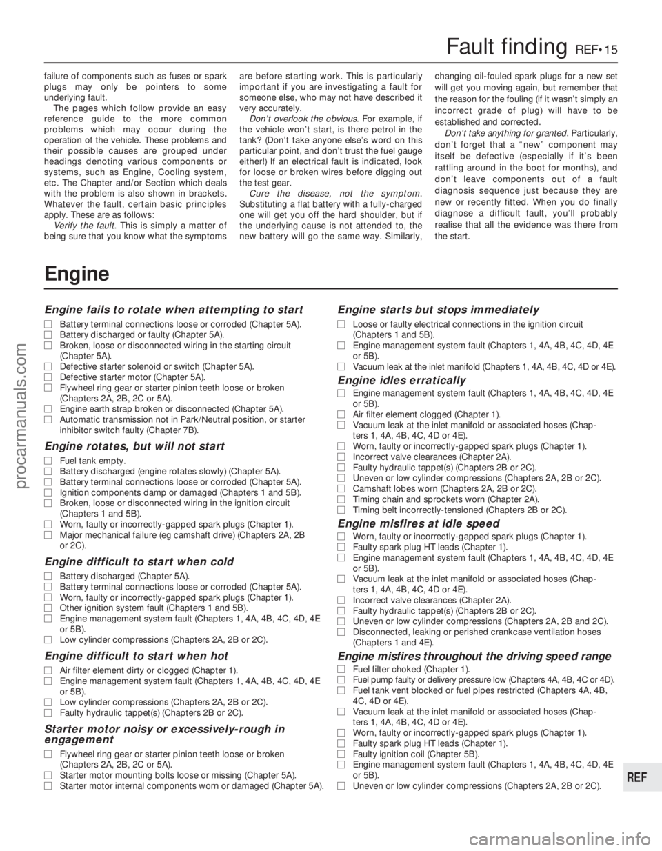
failure of components such as fuses or spark
plugs may only be pointers to some
underlying fault.
The pages which follow provide an easy
reference guide to the more common
problems which may occur during the
operation of the vehicle. These problems and
their possible causes are grouped under
headings denoting various components or
systems, such as Engine, Cooling system,
etc. The Chapter and/or Section which deals
with the problem is also shown in brackets.
Whatever the fault, certain basic principles
apply. These are as follows:
Verify the fault . This is simply a matter of
being sure that you know what the symptoms are before starting work. This is particularly
important if you are investigating a fault for
someone else, who may not have described it
very accurately.
Don’t overlook the obvious . For example, if
the vehicle won’t start, is there petrol in the
tank? (Don’t take anyone else’s word on this
particular point, and don’t trust the fuel gauge
either!) If an electrical fault is indicated, look
for loose or broken wires before digging out
the test gear. Cure the disease, not the symptom .
Substituting a flat battery with a fully-charged
one will get you off the hard shoulder, but if
the underlying cause is not attended to, the
new battery will go the same way. Similarly, changing oil-fouled spark plugs for a new set
will get you moving again, but remember that
the reason for the fouling (if it wasn’t simply an
incorrect grade of plug) will have to be
established and corrected.
Don’t take anything for granted . Particularly,
don’t forget that a “new” component may
itself be defective (especially if it’s been
rattling around in the boot for months), and
don’t leave components out of a fault
diagnosis sequence just because they are
new or recently fitted. When you do finally
diagnose a difficult fault, you’ll probably
realise that all the evidence was there from
the start.
Fault findingREF•15
REF
Engine
Engine fails to rotate when attempting to start
m
m Battery terminal connections loose or corroded (Chapter 5A).
m
m Battery discharged or faulty (Chapter 5A).
m
m Broken, loose or disconnected wiring in the starting circuit
(Chapter 5A).
m m Defective starter solenoid or switch (Chapter 5A).
m
m Defective starter motor (Chapter 5A).
m
m Flywheel ring gear or starter pinion teeth loose or broken
(Chapters 2A, 2B, 2C or 5A).
m m Engine earth strap broken or disconnected (Chapter 5A).
m
m Automatic transmission not in Park/Neutral position, or starter
inhibitor switch faulty (Chapter 7B).
Engine rotates, but will not start
m mFuel tank empty.
m
m Battery discharged (engine rotates slowly) (Chapter 5A).
m
m Battery terminal connections loose or corroded (Chapter 5A).
m
m Ignition components damp or damaged (Chapters 1 and 5B).
m
m Broken, loose or disconnected wiring in the ignition circuit
(Chapters 1 and 5B).
m m Worn, faulty or incorrectly-gapped spark plugs (Chapter 1).
m
m Major mechanical failure (eg camshaft drive) (Chapters 2A, 2B
or 2C).
Engine difficult to start when cold
m mBattery discharged (Chapter 5A).
m
m Battery terminal connections loose or corroded (Chapter 5A).
m
m Worn, faulty or incorrectly-gapped spark plugs (Chapter 1).
m
m Other ignition system fault (Chapters 1 and 5B).
m
m Engine management system fault (Chapters 1, 4A, 4B, 4C, 4D, 4E
or 5B).
m m Low cylinder compressions (Chapters 2A, 2B or 2C).
Engine difficult to start when hot
m
mAir filter element dirty or clogged (Chapter 1).
m
m Engine management system fault (Chapters 1, 4A, 4B, 4C, 4D, 4E
or 5B).
m m Low cylinder compressions (Chapters 2A, 2B or 2C).
m
m Faulty hydraulic tappet(s) (Chapters 2B or 2C).
Starter motor noisy or excessively-rough in
engagement
m mFlywheel ring gear or starter pinion teeth loose or broken
(Chapters 2A, 2B, 2C or 5A).
m m Starter motor mounting bolts loose or missing (Chapter 5A).
m
m Starter motor internal components worn or damaged (Chapter 5A).
Engine starts but stops immediately
m
mLoose or faulty electrical connections in the ignition circuit
(Chapters 1 and 5B).
m m Engine management system fault (Chapters 1, 4A, 4B, 4C, 4D, 4E
or 5B).
m m Vacuum leak at the inlet manifold (Chapters 1, 4A, 4B, 4C, 4D or 4E).
Engine idles erratically
m
mEngine management system fault (Chapters 1, 4A, 4B, 4C, 4D, 4E
or 5B).
m m Air filter element clogged (Chapter 1).
m
m Vacuum leak at the inlet manifold or associated hoses (Chap-
ters 1, 4A, 4B, 4C, 4D or 4E).
m m Worn, faulty or incorrectly-gapped spark plugs (Chapter 1).
m
m Incorrect valve clearances (Chapter 2A).
m
m Faulty hydraulic tappet(s) (Chapters 2B or 2C).
m
m Uneven or low cylinder compressions (Chapters 2A, 2B or 2C).
m
m Camshaft lobes worn (Chapters 2A, 2B or 2C).
m
m Timing chain and sprockets worn (Chapter 2A).
m
m Timing belt incorrectly-tensioned (Chapters 2B or 2C).
Engine misfires at idle speed
m
mWorn, faulty or incorrectly-gapped spark plugs (Chapter 1).
m
m Faulty spark plug HT leads (Chapter 1).
m
m Engine management system fault (Chapters 1, 4A, 4B, 4C, 4D, 4E
or 5B).
m m Vacuum leak at the inlet manifold or associated hoses (Chap-
ters 1, 4A, 4B, 4C, 4D or 4E).
m m Incorrect valve clearances (Chapter 2A).
m
m Faulty hydraulic tappet(s) (Chapters 2B or 2C).
m
m Uneven or low cylinder compressions (Chapters 2A, 2B and 2C).
m
m Disconnected, leaking or perished crankcase ventilation hoses
(Chapters 1 and 4E).
Engine misfires throughout the driving speed range
m mFuel filter choked (Chapter 1).
m
m Fuel pump faulty or delivery pressure low (Chapters 4A, 4B, 4C or 4D).\
m
m Fuel tank vent blocked or fuel pipes restricted (Chapters 4A, 4B,
4C, 4D or 4E).
m m Vacuum leak at the inlet manifold or associated hoses (Chap-
ters 1, 4A, 4B, 4C, 4D or 4E).
m m Worn, faulty or incorrectly-gapped spark plugs (Chapter 1).
m
m Faulty spark plug HT leads (Chapter 1).
m
m Faulty ignition coil (Chapter 5B).
m
m Engine management system fault (Chapters 1, 4A, 4B, 4C, 4D, 4E
or 5B).
m m Uneven or low cylinder compressions (Chapters 2A, 2B or 2C).
procarmanuals.com
http://vnx.su
Page 284 of 296
1595 Ford Fiesta Remake
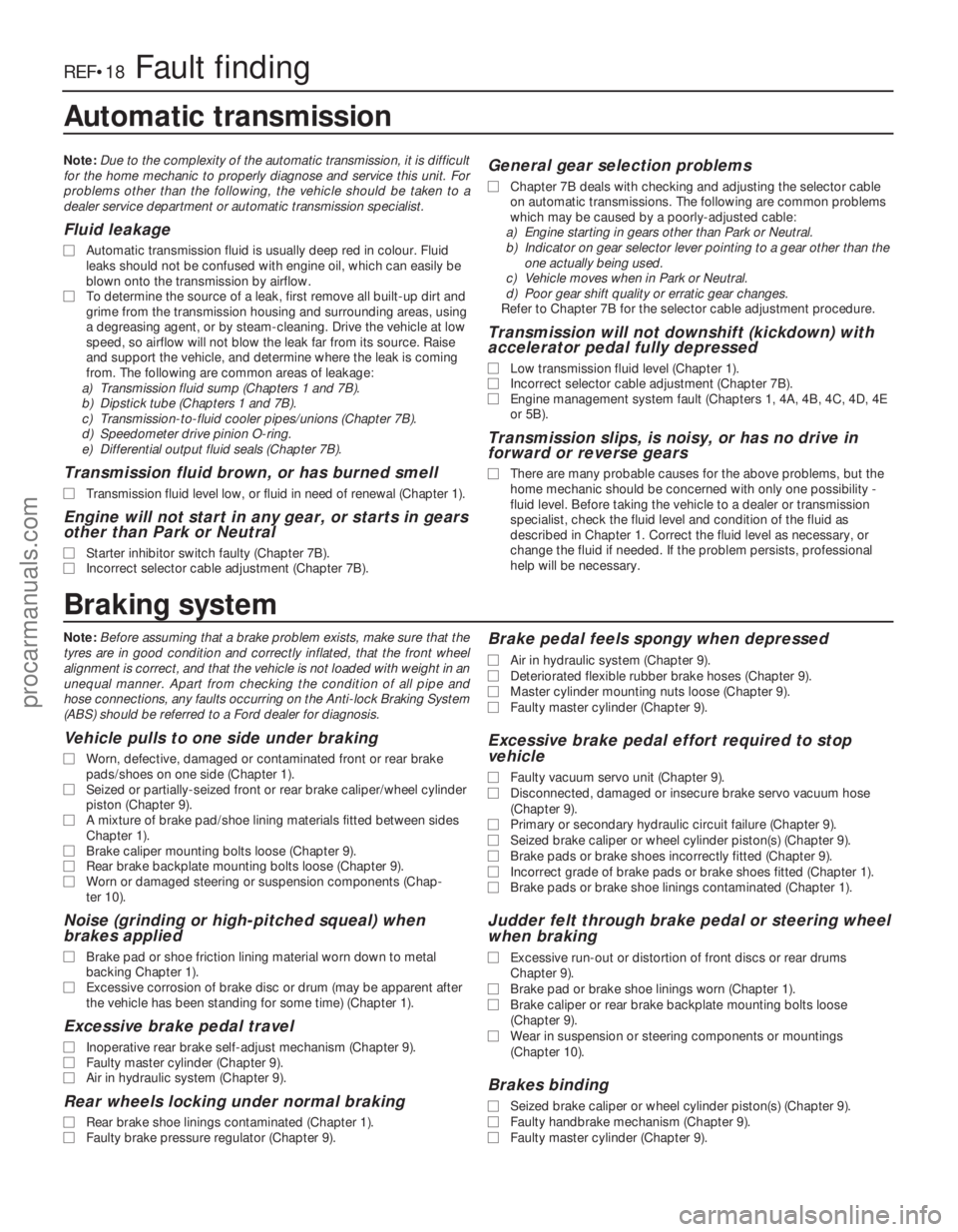
REF•18Fault finding
Braking system
Note:Before assuming that a brake problem exists, make sure that the
tyres are in good condition and correctly inflated, that the front wheel\
alignment is correct, and that the vehicle is not loaded with weight in \
an
unequal manner. Apart from checking the condition of all pipe and
hose connections, any faults occurring on the Anti-lock Braking System
(ABS) should be referred to a Ford dealer for diagnosis.
Vehicle pulls to one side under braking
m m Worn, defective, damaged or contaminated front or rear brake
pads/shoes on one side (Chapter 1).
m m Seized or partially-seized front or rear brake caliper/wheel cylinder
piston (Chapter 9).
m m A mixture of brake pad/shoe lining materials fitted between sides
Chapter 1).
m m Brake caliper mounting bolts loose (Chapter 9).
m
m Rear brake backplate mounting bolts loose (Chapter 9).
m
m Worn or damaged steering or suspension components (Chap-
ter 10).
Noise (grinding or high-pitched squeal) when
brakes applied
m mBrake pad or shoe friction lining material worn down to metal
backing Chapter 1).
m m Excessive corrosion of brake disc or drum (may be apparent after
the vehicle has been standing for some time) (Chapter 1).
Excessive brake pedal travel
m mInoperative rear brake self-adjust mechanism (Chapter 9).
m
m Faulty master cylinder (Chapter 9).
m
m Air in hydraulic system (Chapter 9).
Rear wheels locking under normal braking
m
mRear brake shoe linings contaminated (Chapter 1).
m
m Faulty brake pressure regulator (Chapter 9).
Brake pedal feels spongy when depressed
m
mAir in hydraulic system (Chapter 9).
m
m Deteriorated flexible rubber brake hoses (Chapter 9).
m
m Master cylinder mounting nuts loose (Chapter 9).
m
m Faulty master cylinder (Chapter 9).
Excessive brake pedal effort required to stop
vehicle
m mFaulty vacuum servo unit (Chapter 9).
m
m Disconnected, damaged or insecure brake servo vacuum hose
(Chapter 9).
m m Primary or secondary hydraulic circuit failure (Chapter 9).
m
m Seized brake caliper or wheel cylinder piston(s) (Chapter 9).
m
m Brake pads or brake shoes incorrectly fitted (Chapter 9).
m
m Incorrect grade of brake pads or brake shoes fitted (Chapter 1).
m
m Brake pads or brake shoe linings contaminated (Chapter 1).
Judder felt through brake pedal or steering wheel
when braking
m mExcessive run-out or distortion of front discs or rear drums
Chapter 9).
m m Brake pad or brake shoe linings worn (Chapter 1).
m
m Brake caliper or rear brake backplate mounting bolts loose
(Chapter 9).
m m Wear in suspension or steering components or mountings
(Chapter 10).
Brakes binding
m mSeized brake caliper or wheel cylinder piston(s) (Chapter 9).
m
m Faulty handbrake mechanism (Chapter 9).
m
m Faulty master cylinder (Chapter 9).
Automatic transmission
Note: Due to the complexity of the automatic transmission, it is difficult
for the home mechanic to properly diagnose and service this unit. For
problems other than the following, the vehicle should be taken to a
dealer service department or automatic transmission specialist.
Fluid leakage
m m Automatic transmission fluid is usually deep red in colour. Fluid
leaks should not be confused with engine oil, which can easily be
blown onto the transmission by airflow.
m m To determine the source of a leak, first remove all built-up dirt and
grime from the transmission housing and surrounding areas, using
a degreasing agent, or by steam-cleaning. Drive the vehicle at low
speed, so airflow will not blow the leak far from its source. Raise
and support the vehicle, and determine where the leak is coming
from. The following are common areas of leakage:
a) Transmission fluid sump (Chapters 1 and 7B).
b) Dipstick tube (Chapters 1 and 7B).
c) Transmission-to-fluid cooler pipes/unions (Chapter 7B).
d) Speedometer drive pinion O-ring.
e) Differential output fluid seals (Chapter 7B).
Transmission fluid brown, or has burned smell
m m Transmission fluid level low, or fluid in need of renewal (Chapter 1).\
Engine will not start in any gear, or starts in gears
other than Park or Neutral
m mStarter inhibitor switch faulty (Chapter 7B).
m
m Incorrect selector cable adjustment (Chapter 7B).
General gear selection problems
m
mChapter 7B deals with checking and adjusting the selector cable
on automatic transmissions. The following are common problems
which may be caused by a poorly-adjusted cable:
a) Engine starting in gears other than Park or Neutral.
b) Indicator on gear selector lever pointing to a gear other than the
one actually being used.
c) Vehicle moves when in Park or Neutral.
d) Poor gear shift quality or erratic gear changes.
Refer to Chapter 7B for the selector cable adjustment procedure.
Transmission will not downshift (kickdown) with
accelerator pedal fully depressed
m m Low transmission fluid level (Chapter 1).
m
m Incorrect selector cable adjustment (Chapter 7B).
m
m Engine management system fault (Chapters 1, 4A, 4B, 4C, 4D, 4E
or 5B).
Transmission slips, is noisy, or has no drive in
forward or reverse gears
m mThere are many probable causes for the above problems, but the
home mechanic should be concerned with only one possibility -
fluid level. Before taking the vehicle to a dealer or transmission
specialist, check the fluid level and condition of the fluid as
described in Chapter 1. Correct the fluid level as necessary, or
change the fluid if needed. If the problem persists, professional
help will be necessary.
procarmanuals.com
http://vnx.su
Page 288 of 296
1595 Ford Fiesta Remake
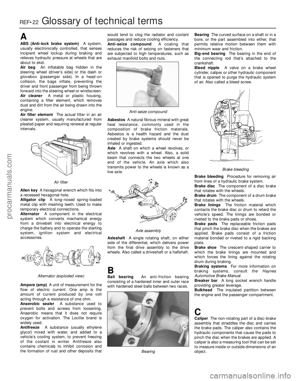
REF•22Glossary of technical terms
A
ABS (Anti-lock brake system)A system,
usually electronically controlled, that senses
incipient wheel lockup during braking and
r elieves hydraulic pressure at wheels that are
about to skid.
Air bag An inflatable bag hidden in the
steering wheel (driver’s side) or the dash or
glovebox (passenger side). In a head-on
collision, the bags inflate, preventing the
driver and front passenger from being thrown
forwar d into the steering wheel or windscreen.
Air cleaner A metal or plastic housing,
containing a filter element, which removes
dust and dirt from the air being drawn into the
engine.
Air filter element The actual filter in an air
cleaner system, usually manufactured fr om
pleated paper and requiring renewal at regular
intervals.
Allen key A hexagonal wrench which fits into
a recessed hexagonal hole.
Alligator clip A long-nosed spring-loaded
metal clip with meshing teeth. Used to make
temporary electrical connections.
Alternator A component in the electrical
system which converts mechanical energy
fr om a drivebelt into electrical energy to
char ge the battery and to operate the starting
system, ignition system and electrical
accessories.
Amper e (amp) A unit of measurement for the
flow of electric current. One amp is the
amount of current produced by one volt
acting through a resistance of one ohm.
Anaer obic sealer A substance used to
pr event bolts and screws from loosening.
Anaer obic means that it does not require
oxygen for activation. The Loctite brand is
widely used.
Antifreeze A substance (usually ethylene
glycol) mixed with water, and added to a
vehicle’ s cooling system, to prevent freezing
of the coolant in winter. Antifreeze also
contains chemicals to inhibit corrosion and
the formation of rust and other deposits that would tend to clog the radiator and coolant
passages and reduce cooling efficiency.
Anti-seize compound A coating that
r educes the risk of seizing on fasteners that
ar e subjected to high temperatures, such as
exhaust manifold bolts and nuts.
Asbestos A natural fibrous mineral with great
heat resistance, commonly used in the
composition of brake friction materials.
Asbestos is a health hazard and the dust
cr eated by brake systems should never be
inhaled or ingested.
Axle A shaft on which a wheel revolves, or
which revolves with a wheel. Also, a solid
beam that connects the two wheels at one
end of the vehicle. An axle which also
transmits power to the wheels is known as a
live axle.
Axleshaft A single rotating shaft, on either
side of the differential, which delivers power
fr om the final drive assembly to the drive
wheels. Also called a driveshaft or a halfshaft.
BBall bearing An anti-friction bearing
consisting of a hardened inner and outer race
with hardened steel balls between two races. Bearing
The curved surface on a shaft or in a
bor e, or the part assembled into either, that
permits relative motion between them with
minimum wear and friction.
Big-end bearing The bearing in the end of
the connecting rod that’s attached to the crankshaft.
Bleed nipple A valve on a brake wheel
cylinder , caliper or other hydraulic component
that is opened to purge the hydraulic system
of air. Also called a bleed screw.
Brake bleeding Procedure for removing air
fr om lines of a hydraulic brake system.
Brake disc The component of a disc brake
that rotates with the wheels.
Brake drum The component of a drum brake
that rotates with the wheels.
Brake linings The friction material which
contacts the brake disc or drum to retard the
vehicle’ s speed. The linings are bonded or
riveted to the brake pads or shoes.
Brake pads The replaceable friction pads
that pinch the brake disc when the brakes are
applied. Brake pads consist of a friction
material bonded or riveted to a rigid backing
plate.
Brake shoe The crescent-shaped carrier to
which the brake linings are mounted and
which forces the lining against the rotating drum during braking.
Braking systems For more information on
braking systems, consult the Haynes
Automotive Brake Manual .
Br eaker bar A long socket wrench handle
pr oviding greater leverage.
Bulkhead The insulated partition between
the engine and the passenger compartment.
CCaliper The non-rotating part of a disc-brake
assembly that straddles the disc and carries
the brake pads. The caliper also contains the
hydraulic components that cause the pads to
pinch the disc when the brakes are applied. A
caliper is also a measuring tool that can be set
to measure inside or outside dimensions of an
object.
Brake bleeding
Bearing
Axle assembly
Anti-seize compound
Alter nator (exploded view)
Air filter
procarmanuals.com
http://vnx.su