1989 FORD FIESTA wheel bolts
[x] Cancel search: wheel boltsPage 87 of 296
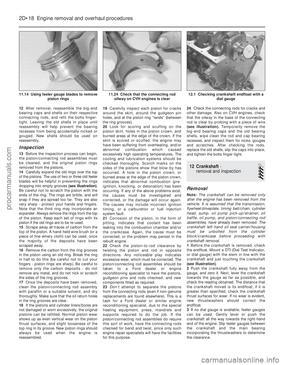
12After removal, reassemble the big-end
bearing caps and shells on their respective
connecting rods, and refit the bolts finger-
tight. Leaving the old shells in place until
reassembly will help prevent the bearing
recesses from being accidentally nicked or
gouged. New shells should be used on
reassembly.
Inspection
13 Before the inspection process can begin,
the piston/connecting rod assemblies must
be cleaned, and the original piston rings
removed from the pistons.
14 Carefully expand the old rings over the top
of the pistons. The use of two or three old feeler
blades will be helpful in preventing the rings
dropping into empty grooves (see illustration).
Be careful not to scratch the piston with the
ends of the ring. The rings are brittle, and will
snap if they are spread too far. They are also
very sharp - protect your hands and fingers.
Note that the third ring may incorporate an
expander. Always remove the rings from the top
of the piston. Keep each set of rings with its
piston if the old rings are to be re-used.
15 Scrape away all traces of carbon from the
top of the piston. A hand-held wire brush (or a
piece of fine emery cloth) can be used, once
the majority of the deposits have been
scraped away.
16 Remove the carbon from the ring grooves
in the piston using an old ring. Break the ring
in half to do this (be careful not to cut your
fingers - piston rings are sharp). Be careful to
remove only the carbon deposits - do not
remove any metal, and do not nick or scratch
the sides of the ring grooves.
17 Once the deposits have been removed,
clean the piston/connecting rod assembly
with paraffin or a suitable solvent, and dry
thoroughly. Make sure that the oil return holes
in the ring grooves are clear.
18 If the pistons and cylinder liners/bores are
not damaged or worn excessively, the original
pistons can be refitted. Normal piston wear
shows up as even vertical wear on the piston
thrust surfaces, and slight looseness of the
top ring in its groove. New piston rings should
always be used when the engine is
reassembled. 19
Carefully inspect each piston for cracks
around the skirt, around the gudgeon pin
holes, and at the piston ring “lands” (between
the ring grooves).
20 Look for scoring and scuffing on the
piston skirt, holes in the piston crown, and
burned areas at the edge of the crown. If the
skirt is scored or scuffed, the engine may
have been suffering from overheating, and/or
abnormal combustion which caused
excessively high operating temperatures. The
cooling and lubrication systems should be
checked thoroughly. Scorch marks on the
sides of the pistons show that blow-by has
occurred. A hole in the piston crown, or
burned areas at the edge of the piston crown,
indicates that abnormal combustion (pre-
ignition, knocking, or detonation) has been
occurring. If any of the above problems exist,
the causes must be investigated and
corrected, or the damage will occur again.
The causes may include incorrect ignition
timing, or a carburettor or fuel injection
system fault.
21 Corrosion of the piston, in the form of
pitting, indicates that coolant has been
leaking into the combustion chamber and/or
the crankcase. Again, the cause must be
corrected, or the problem may persist in the
rebuilt engine.
22 Check the piston-to-rod clearance by
twisting the piston and rod in opposite
directions. Any noticeable play indicates
excessive wear, which must be corrected. The
piston/connecting rod assemblies should be
taken to a Ford dealer or engine
reconditioning specialist to have the pistons,
gudgeon pins and rods checked, and new
components fitted as required.
23 Don’t attempt to separate the pistons
from the connecting rods (even if non-genuine
replacements are found elsewhere). This is a
task for a Ford dealer or similar engine
reconditioning specialist, due to the special
heating equipment, press, mandrels and
supports required to do the job. If the
piston/connecting rod assemblies do require
this sort of work, have the connecting rods
checked for bend and twist, since only such
engine repair specialists will have the facilities
for this purpose. 24
Check the connecting rods for cracks and
other damage. Also on CVH engines, check
that the oilway in the base of the connecting
rod is clear by probing with a piece of wire
(see illustration) . Temporarily remove the
big-end bearing caps and the old bearing
shells, wipe clean the rod and cap bearing
recesses, and inspect them for nicks, gouges
and scratches. After checking the rods,
replace the old shells, slip the caps into place,
and tighten the bolts finger-tight.
12 Crankshaft -
removal and inspection
4
Removal
Note: The crankshaft can be removed only
after the engine has been removed from the
vehicle. It is assumed that the transmission,
flywheel/driveplate, timing belt/chain, cylinder
head, sump, oil pump pick-up/strainer, oil
baffle, oil pump, and piston/connecting rod
assemblies, have already been removed. The
crankshaft left-hand oil seal carrier/housing
must be unbolted from the cylinder
block/crankcase before proceeding with
crankshaft removal.
1 Before the crankshaft is removed, check
the endfloat. Mount a DTI (Dial Test Indicator,
or dial gauge) with the stem in line with the
crankshaft and just touching the crankshaft
(see illustration) .
2 Push the crankshaft fully away from the
gauge, and zero it. Next, lever the crankshaft
towards the gauge as far as possible, and
check the reading obtained. The distance that
the crankshaft moved is its endfloat; if it is
greater than specified, check the crankshaft
thrust surfaces for wear. If no wear is evident,
new thrustwashers should correct the
endfloat.
3 If no dial gauge is available, feeler gauges
can be used. Gently lever or push the
crankshaft all the way towards the right-hand
end of the engine. Slip feeler gauges between
the crankshaft and the main bearing
incorporating the thrustwashers to determine
the clearance.
2D•18 Engine removal and overhaul procedures
12.1 Checking crankshaft endfloat with a dial gauge11.24 Check that the connecting rodoilway on CVH engines is clear11.14 Using feeler gauge blades to remove piston rings
1595Ford Fiesta Remakeprocarmanuals.com
http://vnx.su
Page 89 of 296
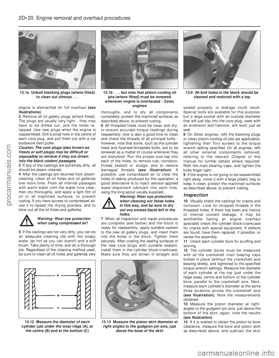
engine is dismantled for full overhaul (see
illustrations) .
2 Remove all oil gallery plugs (where fitted).
The plugs are usually very tight - they may
have to be drilled out, and the holes re-
tapped. Use new plugs when the engine is
reassembled. Drill a small hole in the centre of
each core plug, and pull them out with a car
bodywork dent puller.
Caution: The core plugs (also known as
freeze or soft plugs) may be difficult or
impossible to retrieve if they are driven
into the block coolant passages.
3 If any of the castings are extremely dirty, all
should be steam-cleaned.
4 After the castings are returned from steam-
cleaning, clean all oil holes and oil galleries
one more time. Flush all internal passages
with warm water until the water runs clear,
then dry thoroughly, and apply a light film of
oil to all machined surfaces, to prevent
rusting. If you have access to compressed air,
use it to speed the drying process, and to
blow out all the oil holes and galleries.
Warning: Wear eye protection
when using compressed air!
5 If the castings are not very dirty, you can do
an adequate cleaning job with hot soapy
water (as hot as you can stand!) and a stiff
brush. Take plenty of time, and do a thorough
job. Regardless of the cleaning method used,
be sure to clean all oil holes and galleries very thoroughly, and to dry all components
completely; protect the machined surfaces as
described above, to prevent rusting.
6
All threaded holes must be clean and dry,
to ensure accurate torque readings during
reassembly; now is also a good time to clean
and check the threads of all principal bolts -
however, note that some, such as the cylinder
head and flywheel/driveplate bolts, are to be
renewed as a matter of course whenever they
are disturbed. Run the proper-size tap into
each of the holes, to remove rust, corrosion,
thread sealant or sludge, and to restore
damaged threads (see illustration). If
possible, use compressed air to clear the
holes of debris produced by this operation; a
good alternative is to inject aerosol-applied
water-dispersant lubricant into each hole,
using the long spout usually supplied. Warning: Wear eye protection
when cleaning out these holes
in this way, and be sure to dry
out any excess liquid left in the
holes.
7 When all inspection and repair procedures
are complete (see below) and the block is
ready for reassembly, apply suitable sealant
to the new oil gallery plugs, and insert them
into the holes in the block. Tighten them
securely. After coating the sealing surfaces of
the new core plugs with suitable sealant,
install them in the cylinder block/crankcase.
Make sure they are driven in straight and seated properly, or leakage could result.
Special tools are available for this purpose,
but a large socket with an outside diameter
that will just slip into the core plug, used with
an extension and hammer, will work just as
well.
8
On Zetec engines, refit the blanking plugs
or (new) piston-cooling oil jets (as applicable),
tightening their Torx screws to the torque
wrench setting specified. On all engines, refit
all other external components removed,
referring to the relevant Chapter of this
manual for further details where required.
Refit the main bearing caps, and tighten the
bolts finger-tight.
9 If the engine is not going to be reassembled
right away, cover it with a large plastic bag to
keep it clean; protect the machined surfaces
as described above, to prevent rusting.
Inspection
10 Visually check the castings for cracks and
corrosion. Look for stripped threads in the
threaded holes. If there has been any history
of internal coolant leakage, it may be
worthwhile having an engine overhaul
specialist check the cylinder block/crankcase
for cracks with special equipment. If defects
are found, have them repaired, if possible, or
renew the assembly.
11 Check each cylinder bore for scuffing and
scoring.
12 The cylinder bores must be measured
with all the crankshaft main bearing caps
bolted in place (without the crankshaft and
bearing shells), and tightened to the specified
torque wrench settings. Measure the diameter
of each cylinder at the top (just under the
ridge area), centre and bottom of the cylinder
bore, parallel to the crankshaft axis. Next,
measure each cylinder’s diameter at the same
three locations across the crankshaft axis
(see illustration) . Note the measurements
obtained.
13 Measure the piston diameter at right-
angles to the gudgeon pin axis, just above the
bottom of the skirt; again, note the results
(see illustration) .
14 If it is wished to obtain the piston-to-bore
clearance, measure the bore and piston skirt
as described above, and subtract the skirt
2D•20 Engine removal and overhaul procedures
13.13 Measure the piston skirt diameter at
right-angles to the gudgeon pin axis, just
above the base of the skirt13.12 Measure the diameter of each
cylinder just under the wear ridge (A), at
the centre (B) and at the bottom (C)
13.6 All bolt holes in the block should be cleaned and restored with a tap13.1b . . . but note that piston-cooling oiljets (where fitted) must be renewed
whenever engine is overhauled - Zetec engines13.1a Unbolt blanking plugs (where fitted)to clean out oilways . . .
1595Ford Fiesta Remakeprocarmanuals.com
http://vnx.su
Page 91 of 296
necessary for reassembly of the engine are at
hand. In addition to all normal tools and
materials, jointing and thread locking
compound will be needed during engine
reassembly. For general-purpose applications,
it is recommended that Loctite 275 setting
sealer or Hylomar PL32M non-setting sealer
be used for joints where required, and
Loctite 270 for stud and bolt thread-locking.
For specific applications on Zetec engines,
Hylosil 102 for the cylinder block/crankcase-
to-sump/oil pump/oil seal carrier joints, and
Loctite 518 for the camshaft right-hand
bearing caps should be used. These are
recommended by, and obtained from, Ford
dealers. In all other cases, provided the
relevant mating surfaces are clean and flat,
new gaskets will be sufficient to ensure joints
are oil-tight. Do notuse any kind of silicone-
based sealant on any part of the fuel system or
inlet manifold, and neveruse exhaust sealants
upstream of the catalytic converter.
2 In order to save time and avoid problems,
engine reassembly can be carried out in the
following order (as applicable).
a) Engine ventilation cap (CVH and PTE engines).
b) Tappets and camshaft (HCS engines).
c) Crankshaft and main bearings.
d) Pistons and connecting rods.
e) Oil pump.
f) Sump.
g) Flywheel/driveplate.
h) Cylinder head.
i) Timing sprockets and chain/belt.
j) Engine external components.
3 Ensure that everything is clean prior to
reassembly. As mentioned previously, dirt and
metal particles can quickly destroy bearings
and result in major engine damage. Use clean
engine oil to lubricate during reassembly.
16 Piston rings - refitting
2
1Before installing new piston rings, check
the end gaps. Lay out each piston set with a
piston/connecting rod assembly, and keep them together as a matched set from now on.
2
Insert the top compression ring into the first
cylinder, and square it up with the cylinder
walls by pushing it in with the top of the
piston. The ring should be near the bottom of
the cylinder, at the lower limit of ring travel.
3 To measure the end gap, slip feeler gauges
between the ends of the ring, until a gauge
equal to the gap width is found. The feeler
gauge should slide between the ring ends
with a slight amount of drag. Compare the
measurement to the value given in the
Specifications in this Chapter; if the gap is
larger or smaller than specified, double-check to make sure you have the correct rings
before proceeding. If you are assessing the
condition of used rings, have the cylinder
bores checked and measured by a Ford
dealer or similar engine reconditioning
specialist, so that you can be sure of exactly
which component is worn, and seek advice as
to the best course of action to take.
4 If the end gap is still too small, it must be
opened up by careful filing of the ring ends
using a fine file. If it is too large, this is not as
serious, unless the specified limit is exceeded,
in which case very careful checking is
required of the dimensions of all components,
as well as of the new parts.
5 Repeat the procedure for each ring that will
be installed in the first cylinder, and for each
ring in the remaining cylinders. Remember to
keep rings, pistons and cylinders matched up.
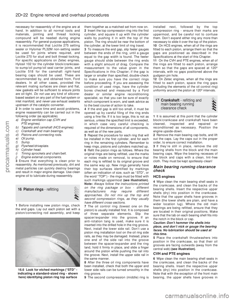
6 Refit the piston rings as follows. Where the
original rings are being refitted, use the marks
or notes made on removal, to ensure that
each ring is refitted to its original groove and
the same way up. New rings generally have
their top surfaces identified by markings
(often an indication of size, such as “STD”, or
the word “TOP”) - the rings must be fitted with
such markings uppermost (see illustration) .
Note: Always follow the instructions printed
on the ring package or box - different
manufacturers may require different
approaches. Do not mix up the top and
second compression rings, as they usually
have different cross-sections.
7 The oil control ring (lowest one on the
piston) is usually installed first. It is composed
of three separate elements. Slip the
spacer/expander into the groove. If an
anti- rotation tang is used, make sure it is
inserted into the drilled hole in the ring groove.
Next, install the lower side rail. Don’t use a
piston ring installation tool on the oil ring side
rails, as they may be damaged. Instead, place
one end of the side rail into the groove
between the spacer/expander and the ring
land, hold it firmly in place, and slide a finger
around the piston while pushing the rail into
the groove. Next, install the upper side rail in
the same manner.
8 After the three oil ring components have
been installed, check that both the upper and
lower side rails can be turned smoothly in the
ring groove.
9 The second compression (middle) ring is installed next, followed by the top
compression ring - ensure their marks are
uppermost, and be careful not to confuse
them. Don’t expand either ring any more than
necessary to slide it over the top of the piston.
10
On HCS engines, when all of the rings are
fitted to each piston, arrange them so that the
gaps are positioned as described in the
Specifications at the start of this Chapter.
11 On the CVH and PTE engines, when all of
the rings are fitted to each piston, arrange
them so that the gaps are spaced at 120º
intervals, with no gaps positioned above the
gudgeon pin hole.
12 On Zetec engines, when all the rings are
fitted to each piston, space the ring gaps
(including the elements of the oil control ring)
uniformly around the piston at 120º intervals.
17 Crankshaft - refitting and
main bearing running
clearance check
4
1 It is assumed at this point that the cylinder
block/crankcase and crankshaft have been
cleaned, inspected and repaired or
reconditioned as necessary. Position the
engine upside-down.
2 Remove the main bearing cap bolts, and lift
out the caps. Lay the caps out in the proper
order, to ensure correct installation.
3 If they’re still in place, remove the old
bearing shells from the block and the main
bearing caps. Wipe the bearing recesses of
the block and caps with a clean, lint-free
cloth. They must be kept spotlessly-clean!
Main bearing running clearance
check
HCS engines
4 Wipe clean the main bearing shell seats in
the crankcase, and clean the backs of the
bearing shells. Insert the respective upper
shells (dry) into position in the crankcase.
Note that the upper shells have grooves in
them (the lower shells are plain, and have a
wider location lug). Where the old main
bearings are being refitted, ensure that they
are located in their original positions. Make
sure that the tab on each bearing shell fits into
the notch in the block or cap.
Caution: Don’t hammer the shells into
place, and don’t nick or gouge the bearing
faces. No lubrication should be used at
this time.
5 Place the crankshaft thrustwashers into
position in the crankcase, so that their oil
grooves are facing outwards (away from the
central web) (see illustration) .
CVH and PTE engines
6Wipe clean the main bearing shell seats in
the crankcase, and clean the backs of the
bearing shells. Insert the respective upper
shells (dry) into position in the crankcase.
Note that with the exception of the front main
bearing, the upper shells have grooves in
2D•22 Engine removal and overhaul procedures
16.6 Look for etched markings (“STD” -
indicating a standard-sized ring - shown
here) identifying piston ring top surface
1595Ford Fiesta Remakeprocarmanuals.com
http://vnx.su
Page 110 of 296
position at the carburettor, then secure the
outer cable with its retaining clip.
Adjustment
12To check that the choke cable is correctly
adjusted, the control knob must be pulled out
to the full-on position and the choke lever
must be in contact with its stop. Adjust as
required if necessary.
13 Press the choke knob fully in (to the off
position), then check that the choke linkage at
the carburettor has fully returned to its off
position and the choke valve plate in the
carburettor is at a right angle (90º) to the
venturi.
14 Refit the air cleaner.
15 Reconnect the battery, turn the ignition
on, operate the choke and check that the
choke warning light operates correctly.
7 Fuel pump -
testing, removal and refitting
2
Note: Refer to the warning note in Section 1
before proceeding.
Testing
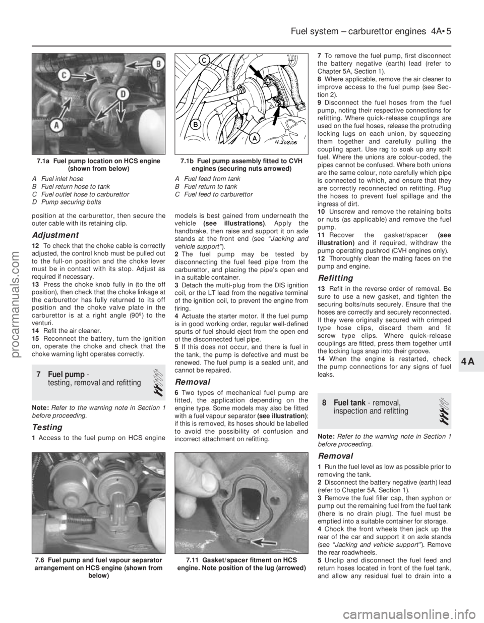
1 Access to the fuel pump on HCS engine models is best gained from underneath the
vehicle
(see illustrations) . Apply the
handbrake, then raise and support it on axle
stands at the front end (see “Jacking and
vehicle support” ).
2 The fuel pump may be tested by
disconnecting the fuel feed pipe from the
carburettor, and placing the pipe’s open end
in a suitable container.
3 Detach the multi-plug from the DIS ignition
coil, or the LT lead from the negative terminal
of the ignition coil, to prevent the engine from
firing.
4 Actuate the starter motor. If the fuel pump
is in good working order, regular well-defined
spurts of fuel should eject from the open end
of the disconnected fuel pipe.
5 If this does not occur, and there is fuel in
the tank, the pump is defective and must be
renewed. The fuel pump is a sealed unit, and
cannot be repaired.
Removal
6 Two types of mechanical fuel pump are
fitted, the application depending on the
engine type. Some models may also be fitted
with a fuel vapour separator (see illustration) ;
if this is removed, its hoses should be labelled
to avoid the possibility of confusion and
incorrect attachment on refitting. 7
To remove the fuel pump, first disconnect
the battery negative (earth) lead (refer to
Chapter 5A, Section 1).
8 Where applicable, remove the air cleaner to
improve access to the fuel pump (see Sec-
tion 2).
9 Disconnect the fuel hoses from the fuel
pump, noting their respective connections for
refitting. Where quick-release couplings are
used on the fuel hoses, release the protruding
locking lugs on each union, by squeezing
them together and carefully pulling the
coupling apart. Use rag to soak up any spilt
fuel. Where the unions are colour-coded, the
pipes cannot be confused. Where both unions
are the same colour, note carefully which pipe
is connected to which, and ensure that they
are correctly reconnected on refitting. Plug
the hoses to prevent fuel spillage and the
ingress of dirt.
10 Unscrew and remove the retaining bolts
or nuts (as applicable) and remove the fuel
pump.
11 Recover the gasket/spacer (see
illustration) and if required, withdraw the
pump operating pushrod (CVH engines only).
12 Thoroughly clean the mating faces on the
pump and engine.
Refitting
13 Refit in the reverse order of removal. Be
sure to use a new gasket, and tighten the
securing bolts/nuts securely. Ensure that the
hoses are correctly and securely reconnected.
If they were originally secured with crimped
type hose clips, discard them and fit
screw type clips. Where quick-release
couplings are fitted, press them together until
the locking lugs snap into their groove.
14 When the engine is restarted, check
the pump connections for any signs of fuel
leaks.
8 Fuel tank - removal,
inspection and refitting
3
Note: Refer to the warning note in Section 1
before proceeding.
Removal
1 Run the fuel level as low as possible prior to
removing the tank.
2 Disconnect the battery negative (earth) lead
(refer to Chapter 5A, Section 1).
3 Remove the fuel filler cap, then syphon or
pump out the remaining fuel from the fuel tank
(there is no drain plug). The fuel must be
emptied into a suitable container for storage.
4 Chock the front wheels then jack up the
rear of the car and support it on axle stands
(see “Jacking and vehicle support” ). Remove
the rear roadwheels.
5 Unclip and disconnect the fuel feed and
return hoses located in front of the fuel tank,
and allow any residual fuel to drain into a
Fuel system – carburettor engines 4A•5
7.6 Fuel pump and fuel vapour separator
arrangement on HCS engine (shown from
below)
7.1b Fuel pump assembly fitted to CVHengines (securing nuts arrowed)
A Fuel feed from tank
B Fuel return to tank
C Fuel feed to carburettor7.1a Fuel pump location on HCS engine (shown from below)
A Fuel inlet hose
B Fuel return hose to tank
C Fuel outlet hose to carburettor
D Pump securing bolts
7.11 Gasket/spacer fitment on HCS
engine. Note position of the lug (arrowed)
4A
1595Ford Fiesta Remakeprocarmanuals.com
http://vnx.su
Page 111 of 296
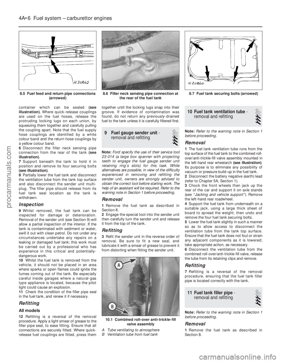
container which can be sealed (see
illustration) . Where quick-release couplings
are used on the fuel hoses, release the
protruding locking lugs on each union, by
squeezing them together and carefully pulling
the coupling apart. Note that the fuel supply
hose couplings are identified by a white
colour band and the return hose couplings by
a yellow colour band.
6 Disconnect the filler neck sensing pipe
connection from the rear of the tank (see
illustration) .
7 Support beneath the tank to hold it in
position and remove its four securing bolts
(see illustration) .
8 Partially lower the fuel tank and disconnect
the ventilation tube from the tank top surface
and also disconnect the sender unit multi-
plug. The filler pipe should release from its
fuel tank seal location as the tank is
withdrawn.
Inspection
9 Whilst removed, the fuel tank can be
inspected for damage or deterioration.
Removal of the sender unit (see Section 9) will
allow a partial inspection of the interior. If the
tank is contaminated with sediment or water,
swill it out with clean petrol. Do not under any
circumstances undertake any repairs on a
leaking or damaged fuel tank; this work must
be carried out by a professional who has
experience in this critical and potentially-
dangerous work.
10 Whilst the fuel tank is removed from the
vehicle, it should not be placed in an area
where sparks or open flames could ignite the
fumes coming out of the tank. Be especially
careful inside garages where a natural-gas
type appliance is located, because the pilot
light could cause an explosion.
11 Check the condition of the filler pipe seal
in the fuel tank, and renew it if necessary.
Refitting
All models
12 Refitting is a reversal of the removal
procedure. Apply a light smear of grease to the
filler pipe seal, to ease fitting. Ensure that all
connections are securely fitted. Where quick-
release fuel couplings are fitted, press them together until the locking lugs snap into their
groove. If evidence of contamination was
found, do not return any previously-drained
fuel to the tank unless it is carefully filtered first.
9
Fuel gauge sender unit -
removal and refitting
3
Note: Ford specify the use of their service tool
23-014 (a large box spanner with projecting
teeth to engage the fuel gauge sender unit
retaining ring’s slots) for this task. While
alternatives are possible, in view of the difficulty
experienced in removing and refitting the
sender unit, owners are strongly advised to
obtain the correct tool before starting work. The
help of an assistant will be required. Refer to the
warning note in Section 1 before proceeding.
Removal
1 Remove the fuel tank as described in
Section 8.
2 Engage the special tool into the sender unit
then carefully turn the sender unit and release
it from the top of the tank.
Refitting
3 Refit the sender unit in the reverse order of
removal. Be sure to fit a new seal, and
lubricate it with a smear of grease to prevent it
from distorting when fitting the sender unit.
10 Fuel tank ventilation tube -
removal and refitting
3
Note: Refer to the warning note in Section 1
before proceeding.
Removal
1 The fuel tank ventilation tube runs from the
top surface of the fuel tank to the combined roll-
over/anti-trickle-fill valve assembly mounted in
the left-hand rear wheelarch (see illustration).
Its purpose is to eliminate any possibility of
vacuum or pressure build-up in the fuel tank.
2 Disconnect the battery negative (earth) lead
(refer to Chapter 5A, Section 1).
3 Chock the front wheels then jack up the
rear of the car and support it on axle stands
(see “Jacking and vehicle support” ). Remove
the left-hand rear roadwheel.
4 Support the fuel tank from underneath on a
suitable jack, using a large thick sheet of
board to spread the weight, then undo and
remove the four fuel tank securing bolts.
5 Lower the fuel tank slightly in such a manner
so as to allow access to disconnect the
ventilation tube from the tank top surface.
Ensure that the fuel tank does not foul or strain
any adjacent components as it is lowered;
take appropriate action, as necessary.
6 Disconnect the ventilation tube from the
combined roll-over/anti-trickle-fill valve, release
the tube from its retaining clips and remove.
Refitting
7 Refitting is a reversal of the removal
procedure, ensuring that the fuel tank filler
pipe is located correctly with the tank.
11 Fuel tank filler pipe -
removal and refitting
3
Note: Refer to the warning note in Section 1
before proceeding.
Removal
1 Remove the fuel tank as described in
Section 8.
4A•6 Fuel system – carburettor engines
10.1 Combined roll-over anti-trickle-fill valve assembly
A Tube ventilating to atmosphere
B Ventilation tube from fuel tank
8.7 Fuel tank securing bolts (arrowed)8.6 Filler neck sensing pipe connection at the rear of the fuel tank
1595Ford Fiesta Remake
8.5 Fuel feed and return pipe connections
(arrowed)procarmanuals.com
http://vnx.su
Page 132 of 296
worn. Apply a smear of anti-seize compound
to the sensor’s threads, to prevent them from
welding themselves to the downpipe in
service. Refit the sensor, tightening it to its
specified torque wrench setting; a slotted
socket will be required to do this. Reconnect
the wiring, and heat shield then refit the
connector plug.
Inlet manifold heater
57The heater is located in a recess in the
inlet manifold, directly underneath the CFi
unit. While access is possible from
underneath, it is preferable, depending on the
tools available, to remove the complete
manifold (Section 15) to reach the heater.
58 Assuming the work is being carried out
without removing the manifold, disconnect
the battery negative (earth) lead (refer to
Chapter 5A, Section 1).
59 Chock the rear wheels then jack up the
front of the car and support it on axle stands
(see “Jacking and vehicle support” ).
60 Disconnect the heater wiring, and extract
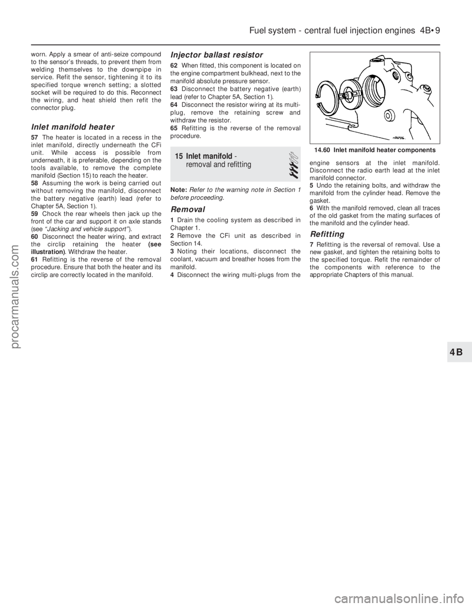
the circlip retaining the heater (see
illustration) . Withdraw the heater.
61 Refitting is the reverse of the removal
procedure. Ensure that both the heater and its
circlip are correctly located in the manifold.
Injector ballast resistor
62 When fitted, this component is located on
the engine compartment bulkhead, next to the
manifold absolute pressure sensor.
63 Disconnect the battery negative (earth)
lead (refer to Chapter 5A, Section 1).
64 Disconnect the resistor wiring at its multi-
plug, remove the retaining screw and
withdraw the resistor.
65 Refitting is the reverse of the removal
procedure.
15 Inlet manifold -
removal and refitting
3
Note: Refer to the warning note in Section 1
before proceeding.
Removal
1 Drain the cooling system as described in
Chapter 1.
2 Remove the CFi unit as described in
Section 14.
3 Noting their locations, disconnect the
coolant, vacuum and breather hoses from the
manifold.
4 Disconnect the wiring multi-plugs from the engine sensors at the inlet manifold.
Disconnect the radio earth lead at the inlet
manifold connector.
5
Undo the retaining bolts, and withdraw the
manifold from the cylinder head. Remove the
gasket.
6 With the manifold removed, clean all traces
of the old gasket from the mating surfaces of
the manifold and the cylinder head.
Refitting
7 Refitting is the reversal of removal. Use a
new gasket, and tighten the retaining bolts to
the specified torque. Refit the remainder of
the components with reference to the
appropriate Chapters of this manual.
Fuel system - central fuel injection engines 4B•9
14.60 Inlet manifold heater components
4B
1595Ford Fiesta Remakeprocarmanuals.com
http://vnx.su
Page 135 of 296
Torque wrench settingsNmlbf ft
Idle speed control valve bolts . . . . . . . . . . . . . . . . . . . . . . . . . . . . . . . . . 4 to 5 3 to 4
Fuel pressure regulator bolts . . . . . . . . . . . . . . . . . . . . . . . . . . . . . . . . . 8 to 12 6 to 9
Fuel rail bolts . . . . . . . . . . . . . . . . . . . . . . . . . . . . . . . . . . . .\
. . . . . . . . . 20 to 26 15 to 19
Inlet air temperature sensor . . . . . . . . . . . . . . . . . . . . . . . . . . . . . . . . . . 20 to 25 15 to 18
Inlet manifold . . . . . . . . . . . . . . . . . . . . . . . . . . . . . . . . . . . .\
. . . . . . . . . 16 to 20 12 to 15
Oxygen sensor . . . . . . . . . . . . . . . . . . . . . . . . . . . . . . . . . . . .\
. . . . . . . . 50 to 70 37 to 52
Intercooler-to-radiator bolts . . . . . . . . . . . . . . . . . . . . . . . . . . . . . . . . . . 4 to 6 3 to 5
Boost control valve screws . . . . . . . . . . . . . . . . . . . . . . . . . . . . . . . . . . . 2.2 to 2.7 1.5 to 2
Exhaust manifold heatshield bolts . . . . . . . . . . . . . . . . . . . . . . . . . . . . . 21 to 26 16 to 19
Exhaust manifold-to-engine nuts (non-Turbo models) . . . . . . . . . . . . . . 14 to 17 11 to 13
Exhaust manifold-to-engine nuts (Turbo models) . . . . . . . . . . . . . . . . . 28 to 31 21 to 23
Exhaust manifold-to-turbocharger bolts . . . . . . . . . . . . . . . . . . . . . . . . 20 to 28 15 to 21
Turbocharger-to-exhaust downpipe nuts . . . . . . . . . . . . . . . . . . . . . . . . 35 to 47 26 to 35
Turbocharger cooling pipe banjo union bolts . . . . . . . . . . . . . . . . . . . . . 22 to 29 17 to 22
Turbocharger oil feed and return line couplings . . . . . . . . . . . . . . . . . . . 15 to 20 11 to 15
4C•2 Fuel system - electronic fuel injection engines
1595Ford Fiesta Remake
1 General information and
precautions
General information
The fuel system consists of a fuel tank
(mounted under the body, beneath the rear
seats), fuel hoses, an electric fuel pump
mounted in the fuel tank, and an electronic
fuel injection system. Fuel is supplied under pressure from the
fuel pump to the fuel distributor rail mounted
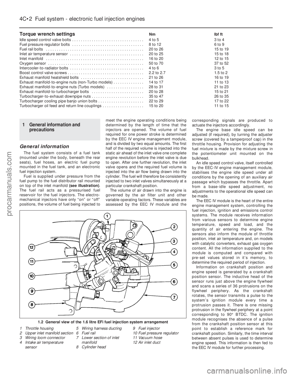
on top of the inlet manifold (see illustration).
The fuel rail acts as a pressurised fuel
reservoir for the fuel injectors. The electro-
mechanical injectors have only “on” or “off”
positions, the volume of fuel being injected to meet the engine operating conditions being
determined by the length of time that the
injectors are opened. The volume of fuel
required for one power stroke is determined
by the EEC IV engine management module,
and is divided by two equal amounts. The first
half of the required volume is injected into the
static air ahead of the inlet valve one complete
engine revolution before the inlet valve is due
to open. After one further revolution, the inlet
valve opens and the required fuel volume is
injected into the air flow being drawn into the
cylinder. The fuel will therefore be consistently
injected to two inlet valves simultaneously at a
particular crankshaft position.
The volume of air drawn into the engine is
governed by the air filter unit and other
variable operating factors. These variables are
assessed by the EEC IV module and the corresponding signals are produced to
actuate the injectors accordingly.
The engine base idle speed can be
adjusted (if required), by turning the adjuster
screw (covered by a tamperproof cap) in the
throttle housing. Provision for adjusting the
fuel mixture is made by the mixture screw in
the potentiometer unit mounted on the
bulkhead. An idle speed control valve, itself controlled
by the EEC-IV engine management module,
stabilises the engine idle speed under all
conditions by the opening of an auxiliary air
passage which bypasses the throttle. Apart
from a base-idle speed adjustment, no
adjustments to the operational idle speed can
be made. The EEC IV module is the heart of the entire
engine management system, controlling the
fuel injection, ignition and emissions control
systems. The module receives information
from various sensors to determine engine
temperature, speed and load, and the
quantity of air entering the engine. The
sensors also inform the module of throttle
position, inlet air temperature and, on models
with catalytic converters, exhaust gas oxygen
content. All the information supplied to the
module is computed and compared with
pre-set values stored in it’s memory, to
determine the required period of injection.
Information on crankshaft position and
engine speed is generated by a crankshaft
position sensor. The inductive head of the
sensor runs just above the engine flywheel
and scans a series of 36 protrusions on the
flywheel periphery. As the crankshaft
rotates, the sensor transmits a pulse to the
system’s ignition module every time a
protrusion passes it. There is one missing
protrusion in the flywheel periphery at a point
corresponding to 90° BTDC. The ignition
module recognises the absence of a pulse
from the crankshaft position sensor at this
point to establish a reference mark for
crankshaft position. Similarly, the time interval
between absent pulses is used to determine
engine speed. This information is then fed to
the EEC IV module for further processing.
1.2 General view of the 1.6 litre EFi fuel injection system arrangement\
1 Throttle housing
2 Upper inlet manifold section
3 Wiring loom connector
4 Intake air temperature sensor 5 Wiring harness ducting
6 Fuel rail
7 Lower section of inlet
manifold
8 Cylinder head 9 Fuel injector
10
Fuel pressure regulator
11 Vacuum hose
12 Air inlet duct
procarmanuals.com
http://vnx.su
Page 141 of 296
15 Inlet manifold-
removal and refitting
4
Note: Refer to the warning note in Section 1
before proceeding.
Removal
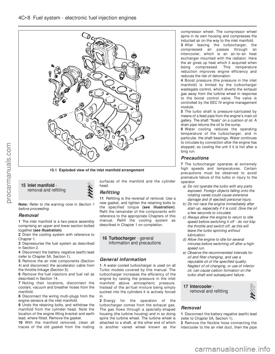
1 The inlet manifold is a two-piece assembly
comprising an upper and lower section bolted
together (see illustration) .
2 Drain the cooling system with reference to
Chapter 1.
3 Depressurise the fuel system as described
in Section 2.
4 Disconnect the battery negative (earth) lead
(refer to Chapter 5A, Section 1).
5 Remove the air inlet components (Section
4) and disconnect the accelerator cable from
the throttle linkage (Section 5).
6 Remove the fuel injectors and fuel rail as
described in Section 14.
7 Noting their locations, disconnect the
coolant, vacuum and breather hoses from the
manifold.
8 Disconnect the wiring multi-plugs from the
engine sensors at the inlet manifold.
9 Undo the retaining bolts, and withdraw the
manifold from the cylinder head. Note the
location of the engine lifting bracket and earth
lead, where fitted. Remove the gasket.
10 With the manifold removed, clean all
traces of the old gasket from the mating surfaces of the manifold and the cylinder
head.
Refitting
11
Refitting is the reversal of removal. Use a
new gasket, and tighten the retaining bolts to
the specified torque (see illustration).
Refit the remainder of the components with
reference to the appropriate Chapters of this
manual. Refill the cooling system as
described in Chapter 1 on completion.
16 Turbocharger - general
information and precautions
General information
1 A water-cooled turbocharger is used on all
Turbo models covered by this manual. The
turbocharger increases the efficiency of the
engine by raising the pressure in the inlet
manifold above atmospheric pressure.
Instead of the air/fuel mixture being simply
sucked into the cylinders it is actively forced
in.
2 Energy for the operation of the
turbocharger comes from the exhaust gas.
The gas flows through a specially-shaped
housing (the turbine housing) and in so doing
spins the turbine wheel. The turbine wheel is
attached to a shaft, at the other end of which
is another vaned wheel known as the compressor wheel. The compressor wheel
spins in its own housing and compresses the
inducted air on the way to the inlet manifold.
3
After leaving the turbocharger, the
compressed air passes through an
intercooler, which is an air-to-air heat
exchanger mounted with the radiator. Here
the air gives up heat which it acquired when
being compressed. This temperature
reduction improves engine efficiency and
reduces the risk of detonation.
4 Boost pressure (the pressure in the inlet
manifold) is limited by the turbocharger
wastegate control, which diverts the exhaust
gas away from the turbine wheel in response
to the boost control valve. The valve is
controlled by the EEC IV engine management
module.
5 The turbo shaft is pressure-lubricated by
means of a feed pipe from the engine’s main oil
gallery. The shaft “floats” on a cushion of oil. A
drain pipe returns the oil to the sump.
6 Water cooling reduces the operating
temperature of the turbocharger, and in
particular, the shaft bearings. Water continues
to circulate by convection after the engine has
stopped, so cooling the unit if it is hot after a
long run.
Precautions
7 The turbocharger operates at extremely
high speeds and temperatures. Certain
precautions must be observed to avoid
premature failure of the turbo or injury to the
operator. a) Do not operate the turbo with any parts
exposed. Foreign objects falling onto the
rotating vanes could cause extensive
damage and (if ejected) personal injury.
b) Do not race the engine immediately after
start-up, especially if it is cold. Give the oil
a few seconds to circulate.
c) Always allow the engine to return to idle
speed before switching it off - do not blip
the throttle and switch off, as this will
leave the turbo spinning without
lubrication.
d) Allow the engine to idle for several
minutes before switching off after a high-
speed run.
e) Observe the recommended intervals for oil and filter changing, and use a
reputable oil of the specified quality.
Neglect of oil changing, or use of inferior
oil, can cause carbon formation on the
turbo shaft and subsequent failure.
17 Intercooler -
removal and refitting
2
Removal
1 Disconnect the battery negative (earth) lead
(refer to Chapter 5A, Section 1).
2 Remove the flexible hose connecting the
intercooler to the air inlet duct, then the pipe
4C•8 Fuel system - electronic fuel injection engines
15.1 Exploded view of the inlet manifold arrangement
1595Ford Fiesta Remakeprocarmanuals.com
http://vnx.su