1988 PONTIAC FIERO air conditioning
[x] Cancel search: air conditioningPage 649 of 1825
6E3-4 2.8L (VIN S) . 5.OL (VIN F) & 5.7L (VIN 8) DRIVEABILITY AND EMISSIONS
ON-CAR SERVICE ..................... C7-3
EGRVALVE
........................ C7-3
EGR Manifold Passage
............... C7-3
EGR Manifold Passage
............... C7-4
ELECTRONIC VACUUM REGULATOR
VALVE
.......................... C7-4
EVRV FILTER REPLACEMENT
.......... C7-4
PARTS INFORMATION
................. C7-4
Exhaust Gas Recirculation Check
Chart C-7
......................... C7-6
SECTION
C8 . 2.8L (VIN S)
TRANSMISISON CONVERTER CLUTCH (TCC) SYSTEM
AND MANUAL TRANSMISSION SHIFT LIGHT
GENERAL DESCRIPTION
................ C8-1
PURPOSE ......................... C8-1
OPERATION ....................... C8-1
DIAGNOSIS
......................... C8-1
SHIFT LIGHT (M/T) DESCRIPTION ........ C8-1
DIAGNOSIS
......................... C8-1
ON-CAR SERVICE ..................... C8-1
Automatic Transmission
Converter Clutch (TCC)
. (1 of 2)
Chart C-8
......................... C8-2
Transmission Converter Clutch
(TCC) Electrical Diagnosis
. (2 of 2)
Chart C-8
......................... C8-4
SECTION C10 . 2.8L (WIN S)
ECM CONTROLLED AIR CONDITIONING
GENERAL DESCRIPTION
................ C10-1
OPERATION ....................... C10-1
DIAGNOSIS ......................... C10-1
ON-CARSERVICE ..................... C10-1
FJC Clutch Control
Chart C-
1 0 ........................ C10-2
SECTION C12 . 2.8L (VlN S)
COOLING FAN CONTROL
GENERAL DESCRIPTION
................ C12-1
OPERATION ....................... C12-1
DIAGNOSIS
......................... C12-1
PARTS INFORMATION ................. C12-1
Cooling Fan Control Circuit (1 of 2)
Chart
C- 12 ........................ C12-2
Cooling Fan Control Circuit (2 of 2)
Chart C-12
........................ C12-4
SECTION C13
. 2.8L (WIN S)
POSITIVE CRANKCASE VENTILATION (PCV)
GENERAL DESCRIPTION
................ C13-1
RESULTS OF INCORRECT OPERATION
.... C13-1
DIAGNOSIS
......................... C13-1
FUNCTIONALCHECK OF PCV VALVE .... C13-1
ON-CAR SERVICE
..................... C13-2
PARTS INFORMATION
................. C13-2
SEC"T0N A . DIAGNOSTIC CHARTS
5.OL (VIN F) & 5.7L (VIN 8)
.................... Table of Contents A-1
Engine Components and Wiring
............... Component Locations A-2
Wiring Diagrams
(1 of 4) ............. A-3
ECM Terminal End View
.............. A-7
Diagnostic Circuit Check
................ A-8
No "Service Engine Soon" Light
......................... Chart A-1 A-10
No ALDL Data
. "Service Engine Soon"
Light "ON" Steady (Won't Flash Code 12)
Chart A-2
......................... A-12
Eng~ne Cranks But Won't Run
Chart A-3
(1 of 2) ................... A-14
Fuel System
Diagnos~s
Chart A-7 (1 of 2) ................... A-18
Cold Start Valve
Chart A-9
......................... A-22
Code 13
. Oxygen Sensor Circuit (Open) .... A-24
Code 14
. Coolant Temperature Sensor Circuit
(High Temp
. Indicated) .............. A-26
Code
1 5 . Coolant Temperature Sensor C~rcuit
. .............. (Low Temp Ind~cated) A-28
Code 21
. Throttle Pos~tlon Sensor (TPS) Circuit
(Signal Voltage High)
............... A-30
Code 22
. Throttle Pos~t~on Sensor (TPS) Circuit
................ (Signal Voltage Low) A-32
Code 23
. Manifold Air Temperature (MAT) Sensor
C~rcuit (Low Temp . Indicated) .......... A-34
Code 24
. Vehicle Speed Sensor
....................... (VSS) Circuit A-36
Code 25
. Manifold Air Temperature (MAT)
Sensor Circuit (High Temp
. Indicated) .... A-38
. ............ Code 32 EGR System Failure A-40
Code 33
. Mass Air Flow (MAF) Sensor Circuit
.................... (GMISECHlgh) A-42
Code 34
. Mass Air Flow (MAF) Sensor Circu~t
.................... (GMISEC Low) A-44
Code 36 Mass Air Flow
(MAF) Sensor
.. ..... ........... Burn-Off Circuit , , A-46
. ........... Code 41 Cyl~nder Select Error A-48
... . Code 42 Electronic Spark Timing Circuit A-50
Code 43 Electronic Spark Control
(ESC)
C~rcuit ....................... A-52
Code 44
. Oxygen Sensor Circu~t
(Lean Exhaust lnd~cated) ............. A-54
Code 45
. Oxygen Sensor Circuit
(Rich Exhaust Indicated)
.............. A-56
Code 54
. Fuel Pump C~rcuit (Lowvoltage) . . 14-58
. ................... Code 51 MEM-CAL A-60
Code 52
. CALPAK Error
.......... (Faulty or Incorrect CALPAK) A-60
. ........... Code 53 System Over Voltage A-60
Page 719 of 1825
6E3-C-1 2.8L (VIN S) DRIVEABILITY AND EMISSIONS
COMPONENT SYSTEMS
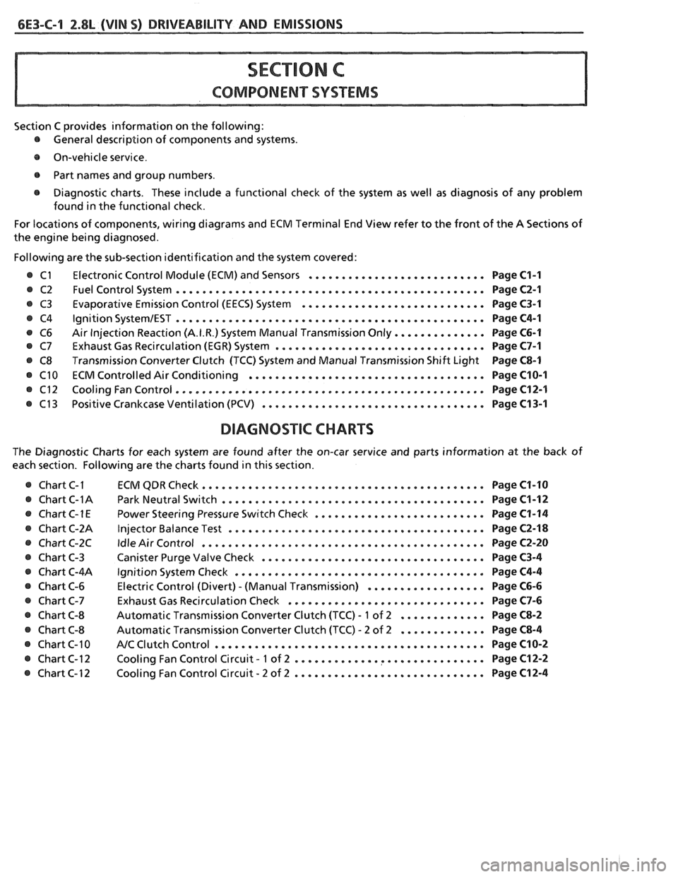
Section C provides information on the following:
@ General description of components and systems .
e On-vehicle service .
@ Part names and group numbers .
@ Diagnostic charts . These include a functional check of the system as well as diagnosis of any problem
found in the functional check
.
For locations of components. wiring diagrams and ECM Terminal End View refer to the front of the A Sections of
the engine being diagnosed
.
Following are the sub-section identification and the system covered:
Electronic Control Module (ECM) and Sensors
........................... Page C1-I
Fuel Control System ............................................... Page C2-1
Evaporative Emission Control (EECS) System ............................ Page C3-1
Ignition SystemIEST ............................................... Page C4-1
Air Injection Reaction (A.I.R.) System Manual Transmission Only .............. Page C6-1
Exhaust Gas Recirculation (EGR) System ................................ Page C7-1
Transmission Converter Clutch (TCC) System and Manual Transmission Shift Light Page C8-1
ECM Controlled Air Conditioning .................................... Page C10-I
Cooling Fan Control ............................................... Page C12-1
Positive Crankcase Ventilation (PCV) .................................. Page C13-1
DIAGNOSTIC CHARTS
The Diagnostic Charts for each system are found after the on-car service and parts information at the back of
each section
. Following are the charts found in this section .
@ Chart C-I
@ Chart C-1A
e ChartC-1E
@ Chart C-2A
e Chart C-2C
@ Chart C-3
@ Chart C-4A
@ Chart C-6
@ Chart C-7
@ Chart C-8
@ Chart C-8
@ Chart C-10
@ Chart C-12
@ Chart C-12 ECM
QDR Check ........................................... Page C1-10
Park
Neutral Switch ........................................ Page C1-12
Power Steering Pressure Switch Check .......................... Page C1-14
Injector Balance Test ....................................... Page C2-18
Idle Air Control ........................................... Page C2-20
Canister Purge Valve Check .................................. Page C3-4
Ignition System Check ...................................... Page C4-4
Electric Control (Divert) . (Manual Transmission) .................. Page C6-6
Exhaust Gas Recirculation Check .............................. Page C7-6
Automatic Transmission Converter Clutch (TCC) . 1 of 2 ............. Page C8-2
Automatic Transmission Converter Clutch (TCC) . 2 of 2 ............. Page C8-4
NC Clutch Control ......................................... Page C10-2
. ............. ............... Cooling Fan Control Circuit 1 of 2 Page C12-2
. ............................. Cooling Fan Control Circuit 2 of 2 Page C12-4
Page 723 of 1825
6E3-Cl-4 2.8L (VIN S) DRIVEABILITY AND EMISSIONS
BarWNeutral Switch (Auto Only)
The ParWNeutral (PIN) switch indicates to the
ECM when the transmission is in Park or Neutral.
This information is used for the TCC and the IAC
valve operation.
Important
Vehicle should not be driven with ParWNeutral
switch disconnected as idle quality will be affected
and a possible false Code
24 (VSS).
See Section "$A" for more information on the PIN
switch, which is part of the neutrallstart and backup
light switch assembly.
NC '"n" Signal
This signal tells the ECM that the A/C selector
Switch is turned on, and that the pressure cycling
switch is closed. The ECM uses this to adjust the idle
Speed when the air conditioning is working.
If this signal is not available to the ECM, idle may
be rough, especially when the
A/C compressor cycles.
The voltage at ECM terminal "B8" should equal
battery voltage when
AIC is requested and the
pressure cycling switch is closed.
The signal at
B8 will cause the ECM to turn on the
A/C clutch by energizing the A/C relay.
Distributor Reference Signal
The distributor sends a signal to the ECM to tell it
both engine RPM and crankshaft position. See EST
System for further information.
To read the codes, use a "Scan" tool or ground the
diagnostic terminal with the engine not running and
the ignition on. The "Service Engine Soon" light will
flash Code 12 three times and
then flash each code
stored in memory three times. All codes stored in
memory would have been read when Code 12 was
flashed again. No new codes can be stored when in the
Diagnostics Mode (diagnostics lead grounded).
This
eliminates confusion while the system is being worked
on. To clear the codes from memory:
@ Ignition off
@ Remove fuse located in a weather proof holder
located near the battery for 30 seconds.
Since the ECM can have
a failure which may
effect only one circuit, following the Diagnostic
Procedures in this section will determine which circuit
has a problem and where it is. If
a diagnostic chart indicates that the ECM
connections or ECM is the cause of
a problem and the
ECM is replaced, but does not correct the problem, one
of the following may be the reason:
€9
connections. - The diagnostic chart will say "ECM
connections or ECM. The terminals may have to be
removed from the connector in order to check them
properly.
@ The ECM or PROM is not correct for the
application.
- The incorrect components may cause a
malfunction and may or may not set a code.
@ The problem is intermittent. - This means that
the problem is not present at the time the system is
being checked. In this case, refer to the "Symptoms"
portion of the manual and make a careful physical
inspection of all portions of the system involved.
@ Shorted solenoid, relay coil, or harness. -
Solenoids and relays are turned "ON" and "OFF" by
the
ECM,using internal electronic switches called
"Drivers". Each driver is part of
a group of four called
"Quad-drivers". Failure of one driver can damage any
other driver in the set.
Solelloid and relay coil
resistance must measure more than 20 ohms. Less
resistance will cause early failure of the ECM
"driver". A shorted solenoid, relay coil, or harness,
with a GMP4 computer, will not damage the ECM, but
will cause the component to be inoperative.
Before replacing an ECM, be sure to check the coil
resistance of all solenoids and relays controlled by the
ECM. See ECM wiring diagram for the
solenoid(s)
and relay(s) and the coil terminal identification.
534636 or BT 8405 testers or equivalent provide
a fast, accurate means of checking for a shorted coil or
a short to battery voltage.
@ The PROM may be faulty. - Although these
rarely fail, it operates as part of the ECM. Therefore,
it could be the cause of the problem. Substitute a
known good PROM.
@ The replacement ECM may be faulty. - After the
ECM is replaced, the system should be rechecked for
proper operation. If the diagnostic chart again
indicates the ECM is the problem, substitute
a known
good ECM. Although this is a rare condition, it could
happen.
ECM
A faulty ECM will be determined in the diagnostic
charts or
by a Code 55.
PROM
A faulty PROM may result in a Code 51.
Page 879 of 1825
6E3-C1-4 5.0L (VIN F) & 5.7L(VIN 8) DRIVEABILITY AND EMISSIONS
See Section "8A" for more information on the PIN
switch, which is part of the neutrallstart and backup
light switch assembly.
NC "ON" Signal
This signal tells the ECM that the NC selector
switch is turned "ON", and that the pressure cycling
switch is closed. The
ECM uses this to adjust the idle
speed when the air conditioning is working.
[f this signal is not available to the ECM, idle may
be rough, especially when the NC compressor cycles.
The voltage at ECM terminal "B8" should equal
battery voltage on a
C60 system and about 5 volts on a
C68 option, when
NC is requested and the pressure
cycling switch is closed.
Distributor Reference Signal
The distributor sends a signal to the ECM to tell it
both engine rpm and crankshaft position. See ignition
system Section
"C4" for further information.
DIAGNOSIS
To read the codes, use a "Scan" tool or ground the
diagnostic terminal with the engine not running and
the ignition "ON". The "Service Engine Soon" light
will flash Code 12 three times and then flash each code
stored in memory three times. All codes stored in
memory would have been read when Code 12 was
flashed again. No new codes can be stored when in the
diagnostics mode (diagnostics lead grounded). This
eliminates confusion while the system is being worked
on.
To clear the codes from memory:
@ Ignition "OFF".
@ Disconnect battery pigtail, located near the
battery, for 30 seconds.
Since the ECM can have a failure which may
affect only one circuit, following the diagnostic
procedures in this section will determine which circuit
has a problem and where it is.
If a diagnostic chart indicates that the
ECM
connections or ECM is the cause of a problem,and the
ECM is replaced, but does not correct the problem, one
of the following may be the reason:
-
@ There is a problem with the ECM terminal
connections.
- The diagnostic chart will say ECM
connections or ECM. The terminals may have to
be removed from the connector in order to check
them properly.
@ The ECM, or Mem-Cal is not correct for the
application.
- The incorrect components may cause
a malfunction and
may or may not set u code.
@ The problem is intermittent. - 'l'his means that the
problem is not present at the time the system is
being checked. In
this case, refer to the "Symptoms" portion
of the
manual and make a careful physical inspection
of
all portions of the system involved.
@ Shorted solenoid, relay coil, or harness. - Solenoids
and relays are turned
"ON" and "OFF" by the
ECM, using internal electronic switches called
"Drivers".
A shorted solenoid, relay coil, or harness in a
GMP4 computer will not damage the ECM,
but will cause the circuit and controlled
component to be inoperative. When the
circuit fault is not present or has been
repaired, the
"Quad-Driver" will again
operate in a normal manner due to it's fault
protected design.
If a fault has been repaired
in a circuit controlled by a "Quad-Driver",
the original ECM should be reinstalled and
the circuit checked for proper operation.
ECM replacement will
not be necessary if the
repaired circuit or component now operates
correctly.
534636 or BT 8405 testers or equivalent provide a
fast, accurate means of checking for a shorted coil
or a short to battery voltage.
@ The Mem-Cal may be faulty. - Although these
rarely fail, it operates as part of the ECM.
Therefore, it could be the cause
of the problem.
Substitute a known good Mem-Cal.
@ The replacement ECM may be faulty - After the
ECM is replaced, the system should be rechecked
for proper operation. If the diagnostic chart again
indicates the ECM is the problem, substitute a
known good ECM. Although this is a rare
condition, it could happen.
ECM
A faulty ECM will be determined in the diagnostic
charts.
MEM-CAL
An incorrect or faulty Mem-Cal, which is part of
the ECM, may set a Code 41 or 52. Also, be sure Mem-
Cal is fully seated and latched in the socket.
ECM INPUTS
A11 of the sensors and input switches can be
diagnosed by the use of
a "Scan" tool. Following is a
short clescription of how the sensors and switches can
he diagnosed
by the use of a "Scan" tool. The "Scan"
can also be used to compare the values for a normal
running engine with the engine you're diagnosing.
Page 972 of 1825
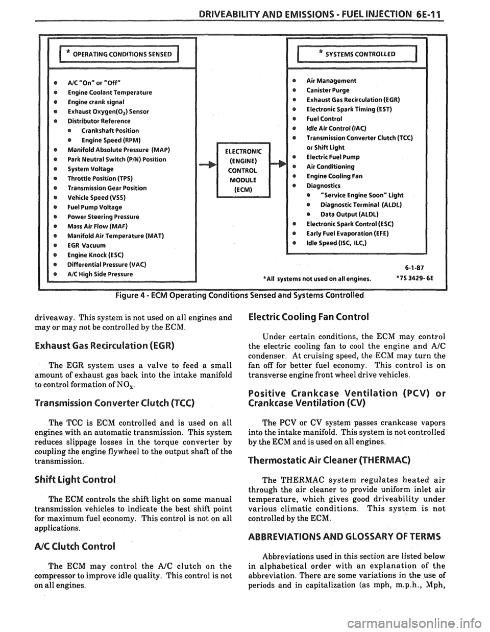
DRIVEABILITY AND EMISSIONS - FUEL INJEC"F0N 6E-11
@ A/% "On" or "Off" r Air Management
r Engine Coolant Temwrature r Canister Purge
@ Engine crank signal r Exhaust Gas Recirculation (EGR)
@ Exhaust Oxygen(02) Sensor @ Electronic Spark Timing (EST)
r Distributor Reference @ Fuel Control
@ Crankshaft Position @ Idle Air Control (lAC)
@ Engine Speed (RPM) Transmission Converter Clutch (TCC)
Manifold Absolute Pressure (MAP)
@ Park Neutral Switch (PB) Position @ Electric Fuel Pump
r System Voltage Air Conditioning
r Throttle Position (TPS) @ Engine Cooling Fan
r Transmission Gear Position
r Vehicle Speed (VSS) @ "Service Engine Soon" Light
@ Fuel Pump Voltage @ Diagnostic Terminal (ALDL)
r Power Steering Pressure @ Data Output (ALDL)
Mass Air Flow (MAF) @ Electronic Spark Control (ESC)
@ Manifold Air Temperature (MAT) @ Early Fuel Evaporation (EFE)
r EGR Vacuum @ Idle Speed (ISC, ILC,)
@ Engine Knock (ESC)
r Differential Pressure (VAC) 6-1-87
*7S
3429- 6E
Figure
4 - ECM Operating Conditions Sensed and Systems Controlled
driveaway. This system is not used on all engines and Electric Cooling Fan Control
may or may not be controlled by the ECM.
Under certain conditions, the
ECM may control
Exhaust Gas Recirculation (ECR) the electric cooling fan to cool the engine and A/C
condenser. At cruising speed, the ECM may turn the
The
EGR system uses a valve to feed a small fan
off for better fuel economy. This control is on
amount of exhaust gas back into the intake manifold transverse
engine front wheel drive vehicles.
to control formation of
NO,.
Positive Crankcase Ventilation (PCV) or
Transmission Converter
Clutch (TCC) Crankcase Ventilation (CV)
The TCC is ECM controlled and is used on all
engines with an automatic transmission. This system
reduces slippage losses in the torque converter by
coupling the engine flywheel to the output shaft of the
transmission.
Shift Light Control
The ECM controls the shift light on some manual
transmission vehicles to indicate the best shift point
for maximum fuel economy. This control is not on all
applications.
NC Clutch Control
The ECM may control the AJC clutch on the
compressor to improve idle quality. This control is not
on all engines. The
PCV or CV system passes crankcase vapors
into the intake manifold. This system is not controlled
by the
ECM and is used on all engines.
Thermostatic Air Cleaner (THERMAC)
The THERMAC system regulates heated air
through the air cleaner to provide uniform inlet air
temperature, which gives good driveability under
various climatic conditions. This system is not
controlled by the
ECM.
ABBREVIATIONS AND GLOSSARY OF TERMS
Abbreviations used in this section are listed below
in alphabetical order with an explanation of the
abbreviation. There are some variations in the use of
periods and in capitalization (as mph,
m.p.h., Mph,
Page 1166 of 1825
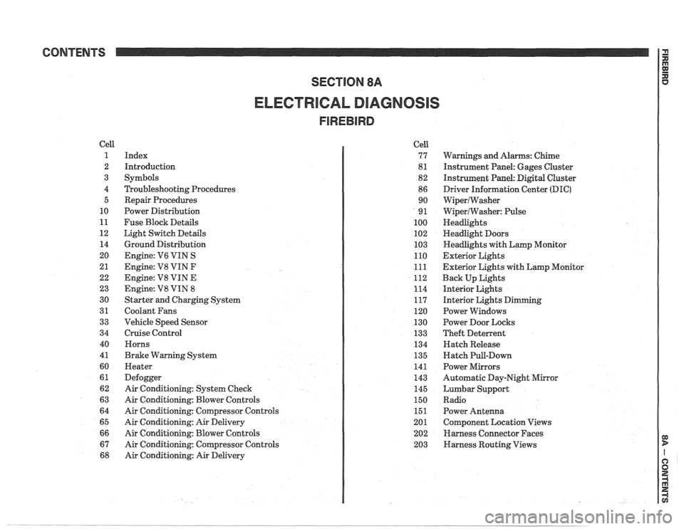
CONTENTS
ELECTRICAL DIAGNOSIS
Cell
1
2
3
4 5
10
11
12 14
20
21
22
23
30
31
33
34
40
4
1
60
61
62
63
64
65
66
67
68
Index
Introduction
Symbols
Troubleshooting Procedures Repair Procedures
Power Distribution
Fuse Block Details
Light Switch Details
Ground Distribution
Engine:
V6 VIN S
Engine: V8 VIN
F
Engine: V8 VIN E
Engine:
V8 VIN 8
Starter and Charging System
Coolant Fans
Vehicle Speed Sensor
Cruise Control Horns
Brake Warning System
Heater
Defogger
Air Conditioning: System Check
Air Conditioning: Blower Controls
Air Conditioning: Compressor Controls
Air Conditioning: Air Delivery
Air Conditioning: Blower Controls
Air Conditioning: Compressor Controls
Air Conditioning: Air Delivery Cell
77
8
1
82
86 90
9
1
100
102
103
110
111
112
114
117
120
130
133
134
135
141
143
145
150
151
201 202
203
Warnings and Alarms: Chime
Instrument Panel: Gages Cluster
Instrument Panel:
Digital Cluster
Driver Information Center
(DIC)
WiperlWasher
WiperlWasher: Pulse
Headlights
Headlight Doors
Headlights with Lamp Monitor
Exterior Lights
Exterior Lights with Lamp Monitor
Back Up Lights
Interior Lights
Interior Lights Dimming
Power Windows
Power Door Locks
Theft Deterrent
Hatch Release
Hatch Pull-Down
Power Mirrors
Automatic Day-Night Mirror
Lumbar Support
Radio Power Antenna
Component Location Views
Harness Connector Faces
Harness Routing Views
Page 1167 of 1825
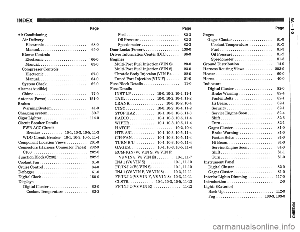
Page
Air Conditioning
Air Delivery
Electronic
.................... 68-0
Manual
....................... 65-0
Blower Controls
Electronic
.................... 66-0
Manual
....................... 63-0
Compressor Controls Electronic
.................... 67-0
Manual
....................... 64-0
................... System Check 62-0
Alarms (Audible)
Chime
......................... 77-0
Antenna(Power) ................... 151-0
Brakes
................. Warning System 41-0
................... Charging system 30-7
...................... Cigar Lighter 114-0
Circuit Breaker Details
PWR ACC Circuit
.......... Breaker 10.1.10.3.10.5.1 1.3
WDO Circuit Breaker
10.1. 10.3. 10.5. 11-4
.......... Component Location Views 201-0
Connectors (Harness Connector Faces) 202-0
el00 .......................... 202-0
............... Junction Block ((2238) 202-2
Coolant Fan
....................... 31-0
Cruise Control
..................... 34-0
Defogger
......................... 61-0
Digital Clock
...................... 150-0
Displays Digital Cluster
.................. 82-0
Coolant Temperature
........... 82-2
Page
......................... Fuel 82-3
................... Oil Pressure 82-2
.................. Speedometer 82-3
................. Door Locks (Power) 130-0
...... Driver Information Center (DIC) 86-0
Engines
... Multi-Port Fuel Injection (VIN S) 20-0
.... Multi-Port Fuel Injection (VIN 8) 23-0
.... Throttle
Body Injection (VIN E) 22-0
...... Tuned
Port Injection (VIN F) 21-0
................. Fuse Block Details 11-0
Fuse Details
........... INST LP 10.0.10.2.10.4.1 1.1
.............. TAIL 10.0.10.2.10.4.1 1.2
................ CRANK 10.0.10.2.1 0.4
.............. CTSY 10~0.10.2.10.4.1 1.2
......... STOP HAZ 10.1.10.3.10.5.1 1.3
............ RADIO 10.1.10.3.10.5.1 1.4
............ WIPER 10.1.10.3.10.5.1 1.4
.................... HATCH 10.2.1 0.4
........... HTR AlC 10.1.10.3.10.5.1 1.4
........... CIH.FAN 10.1.10.3.10.5.1 1.4
......... TURN BIU 10.1.10.3.10.5.1 1.4
............ GAGES 10.1.10.3.10.5.1 1.4
ECM-IGN
(V6 VIN S. V8 VIN F.
........ V8 VIN 8. V8 VIN E) 10.1.1 1.7
............ INJ 1 (V6 VIN S) 10.1.1 1.10
......... FPIINJ 2 (V6 VIN S) 10.1.1 1.10
... INJ 1 (V8 VIN F. V8 VIN 8) 10.3.1 1.11
FPIINJ 2 (V8 VIN F. V8 VIN 8) 10.3.1 1.11
............ CLSTR 10.1.10.3.10.5.1 1.13
............. FPIINJ 2 (V8 VIN E) 11-12
Page
Gages
................... Gages Cluster 81-0
........... Coolant Temperature 81-2
......................... Fuel 81-3
................... Oil Pressure 81-2
.................. Speedometer 81-3
................ Ground Distribution 14-0
Harness Routing Views
............. 203-0
........................... Heater 60-0
............................ Horns 40-0
Indicators
.................. Digital Cluster 82-0
................ Brake Warning 82-4
.................. Fasten Belts 82-1
...................... Hi Beam 82-1
...................... Security 82-1
............ Service Engine Soon 82-4
......................... Shift 82-5
......................... Turn 82-1
................... Gages Cluster 81-0
................ Brake Warning 81-0
.................. Fasten Belts 81-0
...................... Hi Beam 81-0
............ Service Engine Soon 81-0
......................... Shift 81-1
......................... Turn 81-0
Instrument Panel
Digital Cluster
.................. 82-0
Gages Cluster
................... 81-0
............ Interior Lights Dimming 117-0
...................... Introduction 2-0
Lights (Exterior)
........................ Back Up 112-0
...................... Fog 100.3,10 3.0
Page 1169 of 1825
INTRODUCTION 1:
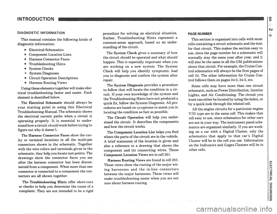
This manual contains the following kinds of
diagnostic information:
e Electrical Schematics
Component Location Lists
@ Harness Connector Faces
@ ?koubleshooting Hints
@ System Checks
System Diagnoses
@ Circuit Operation Descriptions
@ Harness Routing Views
Using these elements together will make elec-
trical troubleshooting faster and easier. Each
element is described below.
The Electrical
Seher~latic should always be
your starting point in using this Electrical
Troubleshooting Manual. The schematic shows
the electrical current paths when a circuit is
operating properly. It is essential to under-
stand how a circuit
should work before trying to
figure out why it doesn't.
The Harness Connector Faces show the cav-
ity or terminal locations in all the multi-pin
connectors shown in the schematic. Together
with the wire colors and terminals given in the
schematic, they help you locate test points. The
drawings show the connector faces you see
after the harness connector has been discon-
nected from a component. When more than one
connector is connected to a component the con-
nectors are all shown together.
The Troubleshooting Hints offer short-cuts
or checks to help you determine the cause of
a
complaint. They are not intended to be a rigid procedure
for solving an electrical situation.
Rather, Troubleshooting Nints represent a
common-sense approach, based on an under-
standing of the circuit.
The System Check gives a summary of how
the circuit should be operated and what should
happen. This is especially important when you
are working on a new system. The System
Check will help you identify symptoms, lead
you to diagnosis and confirm the system after
repair.
The System Diagnosis provides a procedure
to follow that will locate the condition in a cir-
cuit. If your own knowledge of the system and
the Troubleshooting Hints have not produced
a
quick fix, follow the System Diagnosis. All pro-
cedures are based on symptoms to assist you in
locating the condition as fast as possible.
The Circuit Operation will help you under-
stand the circuit. It describes the components
and how the circuit works.
The Component Location List helps you find
where the parts of the circuit are in the vehicle.
A brief statement of the location is given and
also a reference to a drawing that shows the
component and its connecting wires. These
Colnponent Location Views are in cell 201.
Harness Routing Views are found in cell 203.
These views show the routing of the major wir-
ing harnesses and the in-line connectors
between the major harnesses. These views will
make troubleshooting easier when you are not
sure about harness routing.
PAGE NUMBER
This section is organized into cells with most
cells containing a circuit schematic and the text
for that circuit. This makes the section easy to
use, since the page number for a schematic will
normally stay the same year after year, and it
will also be the same in
all the GM publications
about that circuit. For example, the Cruise Con-
trol schematics will always be the first pages of
cell 34. The other information for Cruise Con-
trol follows them on pages
34-2,34-3, etc.
Some cells may have more than one circuit
schematic, such as Power Distribution, Interior
Lights, and Air Conditioning. The circuit you
want can either be located by using the index, or
by a quick look through the related cell.
All the engine circuits for a particular engine
VIN type are in the same cell. This makes that
cell easy to use, since schematics for other cars
are not in your way. The instrument panel sche-
matics are organized similarly. If you are work-
ing on a car with a Digital Cluster, only the
schematics that apply to that car's Digital
Cluster will be in the cell you use. Information
on the Indicators and Gages Clusters will be in
other cells.