1988 PONTIAC FIERO air conditioning
[x] Cancel search: air conditioningPage 240 of 1825
TIRES AND WHEELS 3E-9
Another method is to dismount the tire and
rotate it 180 degrees on the rim. It is important that
this be done on tire and wheel assemblies which are
known to be causing a vibration as it is just as likely to
cause good assemblies to vibrate.
Refer to Section 3, "Vibration Diagnosis" for
more details.
ALUMINUM WHEEL CLEANING
Aluminum wheels should be cleaned and waxed
regularly. Do not use abrasive cleaners, as they could
damage the protective coating.
ALUMINUM WHEEL HUB CAP
Remove or Disconnect
1. Tire and wheel assembly
2. Place a block of wood approximately 2" in
diameter with a squared off end against the back
surface of the cap.
A sharp hammer biow on the
block of wood will
remove the cap.
Install or Connect
1. Place
cap into position at wheel opening and
place a block of wood at least three inches in
diameter against cap face. Install cap by striking
block of wood with hammer.
2. Tire and wheel assembly
NOTICE: Failure to hit cap squarely without the
load distributed evenly could result in permanent
damage to the cap.
ALUMINUM WHEEL POROSITY REPAIR
1. Remove tire and wheel assembly.
2. Locate
leaking areas by inflating tire to 345
kPa
(50 psi) and dipping tire and wheel assembly into
a water bath.
3. Mark
leak areas and remove tire from wheel.
4. Scuff inside surface at leak area with 80 grit
sandpaper and clean area with general purpose
cleaner such as
3M #08984 or equivalent.
5. Apply 1/8" thick layer of adhesive/sealant P/N
1052366 or equivalent to leak area and allow
twelve hours of drying time.
6. Mount tire on wheel, pressurize to 345 kPa (50
psi) and check for leaks.
CAUTION: To avoid serious personal
injury, do not stand over tire when
inflating. Bead may break when bead
snaps over safety hump. Do not
exceed
275 kPa (40 psi) pressure
when inflating any tire if beads are
not seated.
14 275 kPa (40 psi)
pressure will not seat beads, deflate,
relubricate the beads and reinflate.
Overinflation may cause the bead to
break and cause serious personal
injury.
7. Adjust
tire pressure to meet specifications.
8. Balance tire and wheel assembly.
9. Install tire and wheel assembly.
ALUMINUM WHEEL REFINISHING
A protective clear or color coating is applied to
the surface of original equipment cast aluminum
wheels.
A surface degradation condition can begin to
develop if frequent, repeated automatic car wash
cleaning abrades or wears off the factory applied
protective coating. This can happen at some automatic
car wash facilities using aggressive silicon carbide
tipped tire brushes
to clean white walls and tires. Once
the protective coating is
damaged, exposure to caustic
cleaners and/or road salt further causes surface
degradation. The following procedure details how to
strip, clean
and recoat aluminum wheels that are
affected by these conditions.
Required Materials:
A~nchern Alumi Prep #33 - stock
#DX533 or equivalent - cleaning and
conditioning chemical for aluminum.
Amchem Alodine
# 1001 - stock #DXSOT
or equivalent - coating chemical for
aluminum.
Ditzler Delclear Acrylic Urethane Clear
-
stock #DAU-75 or equivalent.
Ditzler Delthane Ultra-Urethane Additive
- stock DXR-80 or equivalent.
Service Procedure:
1. Mark wheel and wheel stud for position on car.
2. Remove tire and wheel assembly from car.
3. Mark location of outboard weights and remove.
4. Wash wheel inside and out with water base all
purpose cleaner. Remove grease and oil with
solvent cleaner.
5. Mask off tire prior to painting.
6. Select and follow the correct procedure,
"Aluminum Damage on Wheel Surface" or
"Clear Coat Damage on Unpainted Wheels".
7. Replace wheel weights with nylon coated
weights.
8. Install tire and wheel assembly on car and tighten
wheel nuts to proper torque.
Accent Color Preparation
1. Sand over painted areas that will not require
recoloring with 400 grit (wet or dry) to promote
adhesion of clear coat.
Aluminum Damage on Wheel Surface
1. Mount tire and wheel on brake lathe and spin
slowly.
2. Sand wheel with backing block or pad by holding
abrasive flat to surface of wheel and moving
slowly back and forth from center to outer edge
to remove damage. Use the following sandpaper
grits in the order listed.
A. Sand with 80 grit
B. Sand with 150 grit
C. Sand with 240 grit
3. Continue with "Recoating Procedure."
Page 347 of 1825
6-2 ENGINE GENERAL INFORMATION
6E3 - Fuel Injection (Ported) This section has information
on all exhaust
system parts, such as tailpipes, mufflers, and the
SECTION 6F - EXHAUST SYSTEM catalytic converter.
GENERAL INFORMAflION
CLEANLINESS AND CARE
An automobile engine is a combination of many
machined, honed, polished and lapped surfaces with
tolerances that are measured in the ten-thousandths of
an inch. When any internal engine parts are serviced,
care and cleanliness are important. A liberal coating of
engine oil should be applied to friction areas during
assembly, to protect and lubricate the surfaces on
initial operation. Throughout this section, it should be
understood that proper cleaning and protection of
machined surfaces and friction areas is part of the
repair procedure. This is considered standard shop
practice, even if not specifically stated. PREVENTING
DAMAGE AND IN
CONTRIBUTING TO RELIABLE ENGINE
PERFORMANCE.
When raising or supporting the engine for any
reason, do not use a jack under the oil pan. Due to the
small clearance between the oil pan and the oil pump
screen, jacking against the oil pan may cause it to be
bent against the pump screen resulting in a damaged
oil pick-up unit.
When working on the engine, remember that the
12-volt electrical system is capable of causing short
circuits. When performing any work where electrical terminals could possibly be grounded, the ground cable
of the battery should be disconnected at the battery.
Any time the carburetor or air cleaner is
train components are removed removed, the intake opening should be covered. This for service, they should be in order' will protect against entrance of foreign be installed in the same locations, and with the same material, which could follow the intake passage into mating surfaces, as when removed
the cylinder and cause extensive damage when the -
Battery cables should be disconnected before any engin; is started.
major work is performed on the engine. Failure to IN THE MECHANICAL PROCEDURES
disconnect cables may result in damage to wire harness DESCRIBED IN THIS SECTION, GENERALLY
or other electrical parts. NO
REFERENCES WILL BE MADE TO THE
REMOVAL OF OPTIONAL EQUIPMENT SUCH
ENGINE SERVICE AS POWER STEERING PUMP, AIR
CONDITIONING COMPRESSOR, ETC.
THE FOLLOWING INFORMATION ON SHOULD IT BECOME NECESSARY TO
ENGINE SERVICE SHOULD BE NOTED REMOVE ANY SUCH ITEM TO
PERFORM
CAREFULLY, AS IT IS IMPORTANT IN OTHER SERVICE, REFER TO THE
APPROPRIATE SECTION OF THIS SERVICE
MANUAL FOR SPECIFIC INFORMATION.
ENGINE PERFORMANCE DIAGNOSIS
INTRODUCTION interchangeably for so long, it was necessary to decide
on the most common usage and then define them. If the
Engine Performance procedures are definition is not understood, and the exact Symptom is
guides that will lead to the most probable causes of not used, the Diagnostic procedure will not work. engine performance complaints. They cover the
components of the fuel, ignition, and mechanical It
is important to keep two facts in mind:
systems that could cause a particular
complaint, and 1. The procedures are written to diagnose problems
then outline repairs in a logical sequence. on cars
that have
"run well at one time" and
that time and wear have created the condition.
It is important to determine if the
"Service ~~~i~~ soon- light is "ON,~' or has come for 2. All possible causes cannot be covered,
a short interval while driving. If the
"Service Engine particularly with regard to emission controls. If
Soon" light has come "ON," the Computer doing the work prescribed does not correct the
Command Control System or DECS should be complaint, then either the wrong Symptom was
checked for stored
"Trouble Codes" (See Diagnostic used, or a more detailed analysis will have to be
Circuit Check, Section 6E, for the engine you are made.
working on) which may indicate the cause for the All of the Symptoms can be caused by worn out
performance
complaint.Each Symptom is defined, and or defective parts such as Spark Plugs, Ignition
it is important that the correct one be selected, based Wiring, etc. If time and/or mileage indicate that
on the complaints reported or found. The definition of parts should be replaced, it is recommended that
each symptom is included with the symptom. it
be done.
The words used may not be what you are used to Refer to:
in all cases, but because these terms have been used
@ Section 6E - Driveability and Emissions
Page 365 of 1825
BA2-14 2.8 LITER V-6
bores for oversize valves use tool 5-5330-1, 2 or 3,
respectively.
VALVE SEATS
Reconditioning the valve seats is very important,
because the seating of the valves must be perfect for the
engine to deliver the power and performance designed
into it.
Another important factor is the cooling of the
valve heads. Good contact between each valve and its
seat in the head is imperative to insure that the heat in
the valve head will be properly carried away.
Several different types of equipment are available
for reseating valve seats. The recommendations of the
manufacturer of the equipment being used should be
carefully followed to attain proper results.
VALVES
Valves that are pitted can be refaced, to the
proper angle, insuring correct relation between the
head and stem, on a valve
refacing machine. Valve
stems which show excessive wear, or valves that are
warped excessively should be replaced. When a valve
head which is warped excessively is
refaced, a knife
edge will be ground on part or all of the valve head due
to the amount of metal that must be removed to
completely
reface the valve. Knife edges lead to
breakage, burning or preignition due to heat localizing
on this knife edge. If the edge of the valve head is less
than
.8mm thick after grinding, replace the valve.
Several different types of equipment are available
for
refacing valves. The recommendations of the
manufacturer of the equipment being used should be
carefully followed to attain the proper results.
Assembly
Insert a valve in the proper port.
Install a valve stem seal over the valve stem and
valve guide base inlet only.
Drop an oil shedder and valve rotator over the
exhaust and a valve spring cap over the valve
spring.
Using tool
5-8062 compress the valve spring.
Install the square cut
"0" ring around the valve
stem in the lower groove, making sure it is not
twisted.
Insert valve, stem key locks and release tool.
Install the valve locks and release the compressor
tool making sure that the locks seat properly in
the upper groove of the valve stem. Grease may
be used to hold the locks in place while releasing
the compressor tool.
Install the remaining valves.
Check each valve stem oil seal by placing valve
stem leak detector, tool J-23994, over the end of
the valve stem and against the cap. Operate the
vacuum pump and make sure no air leaks pass the
seal.
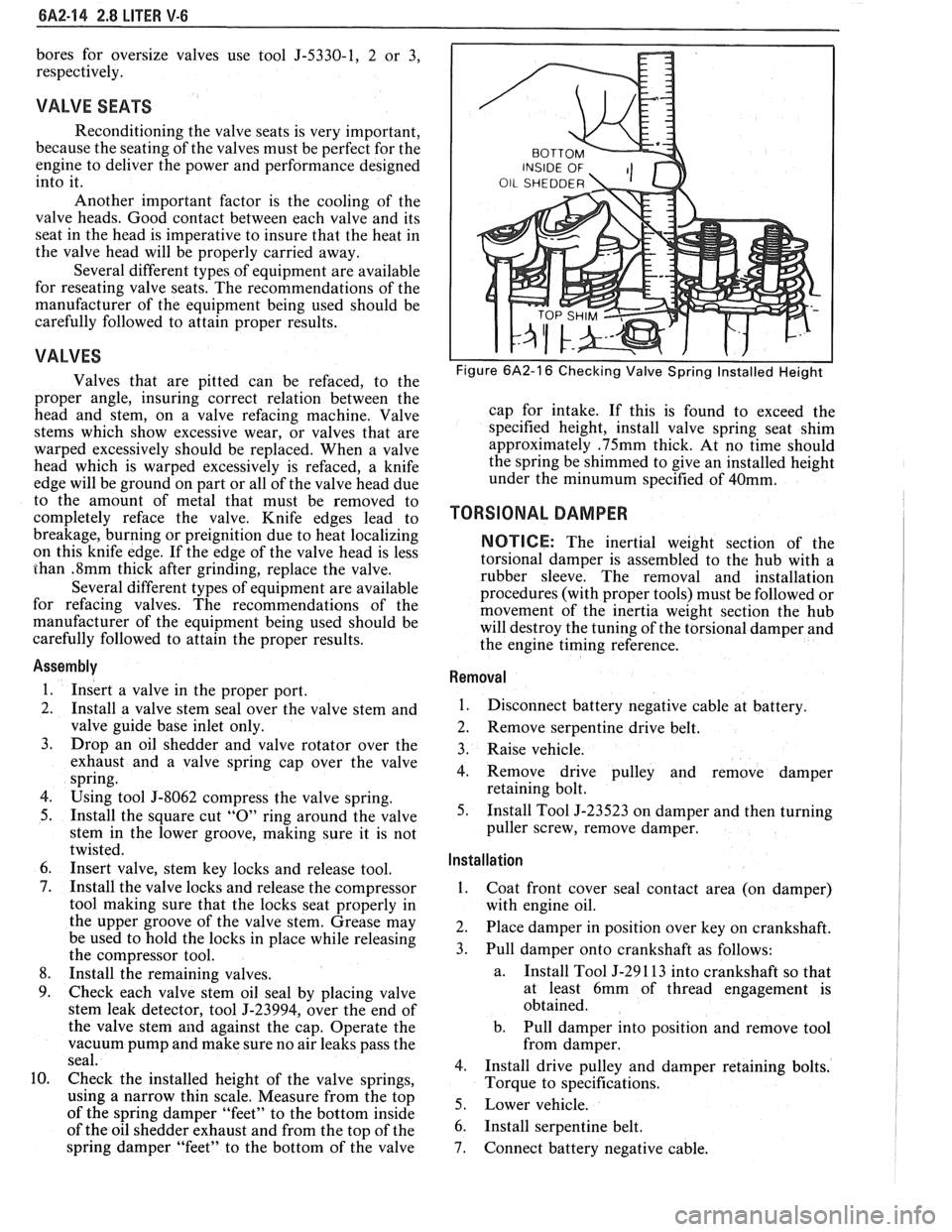
Check the installed height of the valve springs,
using
a narrow thin scale. Measure from the top
of the spring damper "feet" to the bottom inside
of the oil shedder exhaust and from the top of the
spring damper "feet" to the bottom of the valve
Figure 6A2-16 Checking Valve Spring Installed Height
cap for intake. If this is found to exceed the
specified height, install valve spring seat shim
approximately
.75mm thick. At no time should
the spring be shimmed to give an installed height
under the
minumum specified of 40mm.
TORSIONAL DAMPER
NOTICE: The inertial weight section of the
torsional damper is assembled to the hub with a
rubber sleeve. The removal and installation
procedures (with proper tools) must be followed or
movement of the inertia weight section the hub
will destroy the tuning of the torsional damper and
the engine timing reference.
Removal
1.
Disconnect battery negative cable at battery.
2. Remove serpentine drive belt.
3. Raise vehicle.
4. Remove drive pulley and remove damper
retaining bolt.
5. Install Tool J-23523 on damper and then turning
puller screw, remove damper.
Installation ,
1.
Coat front cover seal contact area (on damper)
with engine oil.
2. Place damper in position over key on crankshaft.
3. Pull damper onto crankshaft as follows:
a. Install
Tool J-29 1 13 into crankshaft so that
at least 6mm of thread engagement is
obtained.
b. Pull damper into position and remove tool
from damper.
4. Install drive pulley and damper retaining bolts.
Torque to specifications.
5. Lower vehicle.
6. Install serpentine belt.
7. Connect battery negative cable.
Page 405 of 1825
6A3-26 V-8 ENGINE
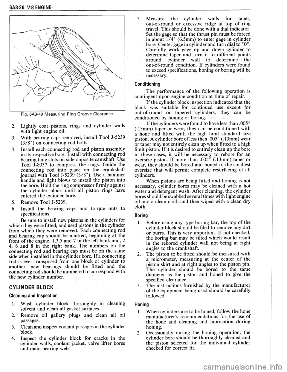
Fig. 6A3-49 Measuring Ring Groove Clearance
2. Lightly coat pistons, rings
and cylinder walls
with light engine oil.
3. With bearing caps removed, install Tool J-5239
(3/8") on connecting rod bolts.
4. Install
each connecting rod and piston assembly
in its respective bore. Install with connecting rod
bearing tang slots on side opposite camshaft. Use
Tool
5-8037 to compress the rings. Guide the
connecting rod into place on the crankshaft
journal with Tool
5-5239 (3/8"). Use a hammer
handle and light blows to install the piston into
the bore. Hold the ring compressor firmly against
the cylinder block until all piston rings have
entered the cylinder bore.
5. Remove Tool J-5239.
6. Install the bearing caps and torque nuts to
specifications.
Be sure to install new pistons in the cylinders for
which they were fitted, and used pistons in the cylinder
from which they were removed. Each connecting rod
and bearing cap should be marked, beginning at the
front of the engine.
1,3,5 and 7 in the left bank and, 2
4, 6 and 8 in the right bank. The numbers on the
connecting rod and bearing cap must be on the same
side when installed in the cylinder bore. If a connecting
rod is ever transposed from one block or cylinder to
another, new bearings should be fitted and the
connecting rod should be numbered to correspond with
the new cylinder number.
CYLINDER BLOCK
Cleaning and Inspection
1. Wash cylinder block thoroughly in cleaning
solvent and clean all gasket surfaces.
2. Remove oil gallery plugs and clean all oil
passages.
3. Clean and inspect coolant passages in the cylinder
block.
4. Inspect the cylinder block for cracks in the
cylinder walls, coolant jacket, valve lifter bores
and main bearing webs. 5.
Measure the cylinder walls for taper,
out-of-round or excessive ridge at top of ring
travel. This should be done with a dial indicator.
Set the gage so that the thrust pin must be forced
in about
1/4" (6.5mm) to enter gage in cylinder
bore. Center gage in cylinder and turn dial to
"0".
Carefully work gage up and down cylinder to
determine taper and turn it to different points
around cylinder wall to determine the
out-of-round condition. If cylinders were found
to exceed specifications, honing or boring will be
necessary.
Conditioning
The performance of the following operation is
contingent upon engine condition at time of repair.
If the cylinder block inspection indicated that the
block was suitable for continued use except for
out-of-round or tapered cylinders, they can be
conditioned by honing or boring.
If the cylinders were found to have less than
.005"
(.13mm) taper or wear, they can be conditioned with
a hone and fitted with the high limit standard size
piston. A cylinder bore of less then
.005" (. 13mm) wear
or taper may not entirely clean up when fitted to a high
limit piston. If it is desired to entirely clean up the bore
in these cases, it will be necessary to
rebore for an
oversize piston. If more than
.005" (. 13mm) taper or
wear, they should be bored and honed to the smallest
oversize that will permit complete resurfacing of all
cylinders.
When pistons are being fitted and honing is not
necessary, cylinder bores may be cleaned with a hot
water and detergent wash. After cleaning, the cylinder
bores should be swabbed several times with light engine
oil and a clean cloth and then wiped with a clean dry
cloth.
Boring
1. Before using any type boring bar, the top of the
cylinder block should be filed to remove any dirt
or burrs. This is very important. If not checked,
the boring bar may be tilted which would result
in the
rebored cylinder wall not being at right
angles to the crankshaft.
2. The
piston to be fitted should be measured with
a micrometer, measuring at the center of the
piston skirt and at right angles to the piston pin.
The cylinder should be bored to the same
diameter as the piston and honed to give the
specified clearance.
3.
The instructions furnished by the manufacturer
of the equipment being used should be carefully
followed.
Honing
1. When cylinders are to be honed, follow the hone
manufacturer's recommendations for the use of
the hone and cleaning and lubrication during
honing.
2. Occasionally during the honing operation, the
cylinder bore should be thoroughly cleaned and
the piston selected for the individual cylinder
checked for correct fit.
Page 412 of 1825
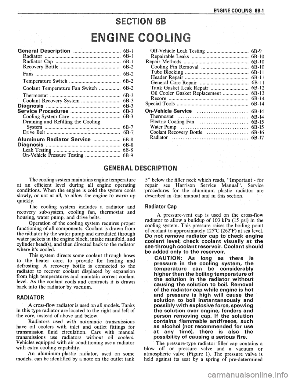
ENGINE COOLING 6B-1
SECTION 6B
NE COOL
General Description ................................ 6B- 1 Off-Vehicle Leak Testing ............................... 6B-9
Radiator
...................................................... 6B- 1 Repairable Leaks ........................ ... .......... 6B- 10
Radiator Cap
......................... .. ............... 6B- 1 Repair Methods ................................................ 6B- 10
Recovery Bottle ......................................... 6B-2 Cooling Fin Removal ................................ 6B- 10 - ............................................. Fans ............................................................... 6B-2 Tube Blocking 6B- 1 1 ............ Header Repair ....................... .... 6B- 1 1 Temperature Switch ..................................... 6B-2 General Core Repair 6B- 1 1 ....................................
........................... Coolant Temperature Fan Switch ................ 6B-2 Tank
Gasket ~eik Repair 6B- 12
................... Thermostat .. 6B-3 Oil
Cooler Gasket Replacement
6B- 13 ............... ................................
...........................................................
Coolant Recovery System 6B-3 Recore 6B- 14 ............................. Special Tools ..................................................... 6B- 14 Diagnosis ..................................................... 6B-3
.............................. ..................................... Service Procedures 6B-3 On-Vehicle Service 6B-14
Cooling System Care
............................... 6B-3 Thermostat ....................................... 6B-14
Draining and Refilling the Cooling Electric Cooling Fan ............................. 6B-15
System
................................................... 6B-7 Water Pump .................... .... ......... 6B-15
Drive Belt
...................... .. .......................... 6B-7 Coolant Recovery Bottle ........................ 6B-16
.......................................... Aluminum Radiator Service .................... 6B-8 Radiator 6B-17
Diagnosis .................................................... 6B-8
Leak Testing
.............................................. 6B-8
On-Vehicle Pressure Testing
...................... .... 6B-9
GENERAL DESCRIPnIBN
The cooling system maintains engine temperature
5" below the filler neck which reads, "Important - for
at an efficient level during all engine operating repair see Harrison Service Manual". Service
conditions. When the engine is cold the system cools procedures for the aluminum plastic radiator are
slowly, or not at all, to allow the engine to warm up described in that manual and in this section.
quickly.
The cooling system includes a radiator and
Radiator Cap
recovery sub-system, cooling fan, thermostat and
housing, water pump, and drive belts.
Operation of the cooling system requires proper
functioning of all components. Coolant is drawn from
the radiator by the water pump and circulated through
water jackets in the engine block, intake manifold, and
cylinder
head(s), and then directed back to the radiator
where it's cooled.
This system directs some coolant through hoses
to the heater core, to provide for heating and
defrosting. A recovery bottle is connected to the
radiator to recover coolant displaced by expansion
from high temperatures and maintain correct coolant
level. As the coolant cools and contracts it is drawn
back into the radiator by vacuum.
RADIATOR
A cross-flow radiator is used on all models. Tanks
in this type radiator are located to the right and left of
the core, instead of above and below.
Radiators used with automatic transmissions
have oil coolers with inlet and outlet fittings for
transmission fluid circulation. Cars with manual
transmissions use radiators without oil coolers.
Vehicles equipped with air conditioning use a radiator
with extra cooling capability.
An aluminum-plastic radiator, used on some
models, can be identified by a note on the outlet tank A pressure-vent
cap is used on the cross-flow
radiator to allow a buildup of
103 kPa (15 psi) in the
cooling system. This pressure raises the boiling point
of coolant to approximately 125°C (262°F) at sea level.
Do not remove radiator cap to check engine
coolant level; check coolant visually at the
see-through coolant reservoir. Coolant should
be added only
to the reservoir.
CAUTION: As long as there
is
pressure in the cooling system, the
temperature can be considerably
higher than the boiling temperature
of
the solution in the radiator without
causing the solution to boil. Removal
of the radiator cap while engine is hot
and pressure is high will cause
the
solution to boil instantaneously and
possibly with explosive
force, spewing
the solution over engine, fenders and
person removing cap. If the solution
contains flammable antifreeze, such
as alcohol (not recommended for use
at any time), there is also the
possibility
of causing a serious fire.
The pressure-type radiator filler cap contains a
blow off or pressure valve and a vacuum or
atmospheric valve (Figure
1). The pressure valve is
held against its seat by a spring of pre-determined
Page 415 of 1825
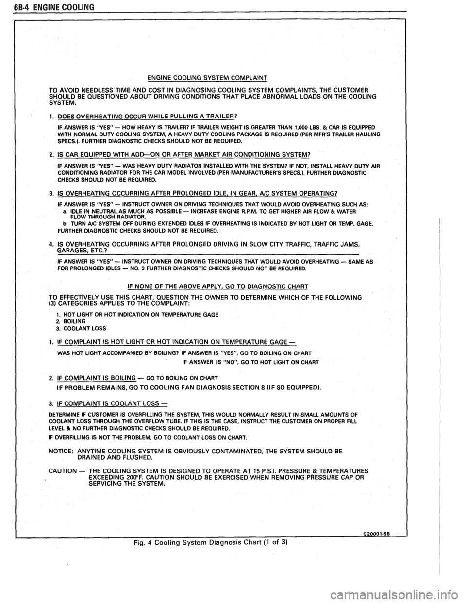
BB.4 ENGINE COOLING
ENGINE COOLING SYSTEM COMPLAINT
TO AVOID NEEDLESS
TIME AND COST IN DIAGNOSING COOLING SYSTEM COMPLAINTS, THE CUSTOMER
SHOULD BE QUESTIONED ABOUT DRIVING CONDITIONS THAT PLACE ABNORMAL LOADS ON THE COOLING
SYSTEM.
1. DOES OVERHEATING OCCUR WHILE PULLING A TRAILER?
IF ANSWER IS "YES'- HOW HEAVY IS TRAILER? IF TRAILER WEIGHT IS GREATER THAN 1,000 LBS. & CAR IS EQUIPPED
WITH NORMAL DUTY COOLING SYSTEM, A HEAVY DUTY COOLING PACKAGE IS REQUIRED (PER MFR'S TRAILER HAULING
SPECS.). FURTHER DIAGNOSTIC CHECKS SHOULD NOT BE REQUIRED.
2. IS CAR EQUIPPED WlTH ADD-ON OR AFTER MARKET AIR CONDITIONING SYSTEM?
IF ANSWER IS "YES"- WAS HEAVY DUTY RADIATOR INSTALLED WITH THE SYSTEM? IF NOT, INSTALL HEAVY DUTY AIR
CONDITIONING RADIATOR FOR THE CAR MODEL INVOLVED (PER MANUFACTURER'S SPECS.). FURTHER DlAGNOSTlC
CHECKS SHOULD NOT BE REQUIRED.
3. IS OVERHEATING OCCURRING AFTER PROLONGED IDLE, IN GEAR, AIC SYSTEM OPERATING?
IF ANSWER IS "YES - INSTRUCT OWNER ON DRIVING TECHNIQUES THAT WOULD AVOID OVERHEATING SUCH AS: a, IDLE IN NEUTRAL AS MUCH AS POSSIBLE - INCREASE ENGINE R.P.M. TO GET HIGHER AIR FLOW & WATER
FLOW THROUGH RADIATOR.
b. TURN A/C SYSTEM OFF DURING EXTENDED IDLES IF OVERHEATING IS INDICATED BY HOT LIGHT OR TEMP. GAGE.
FURTHER DIAGNOSTIC CHECKS SHOULD NOT BE REQUIRED.
4. IS OVERHEATING OCCURRING AFTER PROLONGED DRIVING IN SLOW CITY TRAFFIC, TRAFFIC JAMS,
GARAGES, ETC.?
IF ANSWER IS "YES - INSTRUCT OWNER ON DRIVING TECHNIQUES THAT WOULD AVOID OVERHEATING - SAME AS
FOR PROLONGED IDLES - NO. 3 FURTHER DIAGNOSTIC CHECKS SHOULD NOT BE REQUIRED.
IF NONE OF THE ABOVE APPLY, GO TO DIAGNOSTIC CHART
TO EFFECTIVELY USE THlS CHART, QUESTION THE OWNER TO DETERMINE WHICH OF THE FOLLOWING
(3) CATEGORIES APPLIES TO THE COMPLAINT:
1. HOT LlGHT OR HOT INDICATION ON TEMPERATURE GAGE 2. BOILING 3. COOLANT LOSS
1. IF COMPLAINT IS HOT LlGHT OR HOT INDICATION ON TEMPERATURE GAGE -
WAS HOT LlGHT ACCOMPANIED BY BOILING? IF ANSWER IS "YES", GO TO BOILING ON CHART
IF ANSWER IS "NO, GO TO HOT LlGHT ON CHART
2. IF COMPLAINT IS BOILING - GO TO BOILING ON CHART
IF PROBLEM REMAINS, GO TO COOLING
FAN DIAGNOSIS SECTION 8 (IF SO EQUIPPED).
I 3. IF COMPLAINT IS COOLANT LOSS -
DETERMINE IF CUSTOMER IS OVERFILLING THE SYSTEM, THlS WOULD NORMALLY RESULT IN SMALL AMOUNTS OF
I COOLANT LOSS THROUGH THE OVERFLOW TUBE. IF THlS IS THE CASE, INSTRUCT THE CUSTOMER ON PROPER FILL LEVEL & NO FURTHER DIAGNOSTIC CHECKS SHOULD BE REQUIRED.
I IF OVERFILLING IS NOT THE PROBLEM, GO TO COOLANT LOSS ON CHART.
NOTICE:
ANYTIME COOLING SYSTEM IS OBVIOUSLY CONTAMINATED, THE SYSTEM SHOULD BE
DRAINED AND FLUSHED.
1 CAUTION - THE COOLING SYSTEM IS DESIGNED TO OPERATE AT 15 P.S.I. PRESSURE & TEMPERATURES
EXCEEDING 200°F. CAUTION SHOULD BE EXERCISED WHEN REMOVING PRESSURE CAP OR
I SERVICING THE SYSTEM.
Fig. 4 Cooling System Diagnosis Chart (I of 3)
Page 418 of 1825
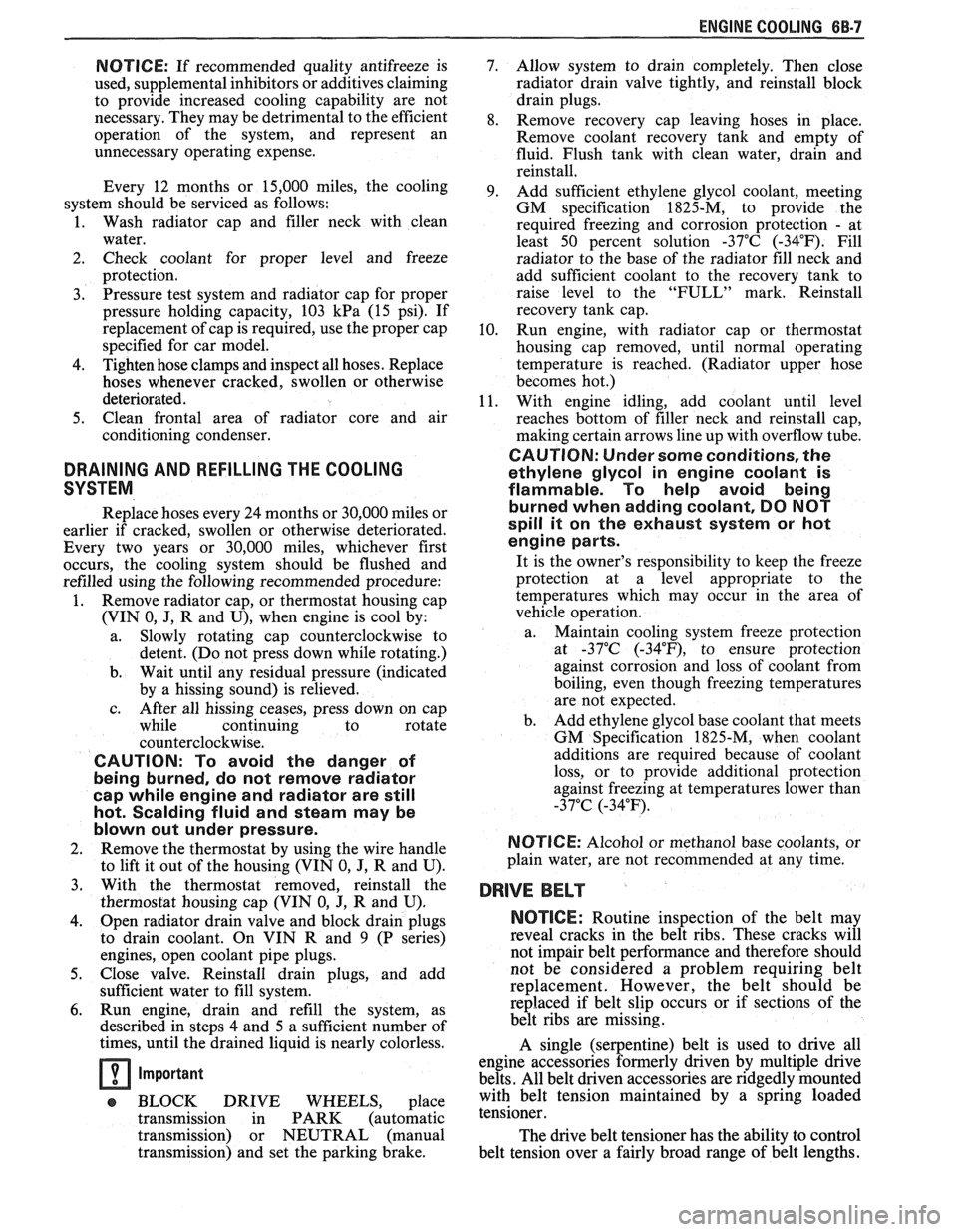
ENGINE COOLING BB-7
NOTICE: If recommended quality antifreeze is
used, supplemental inhibitors or additives claiming
to provide increased cooling capability are not
necessary. They may be detrimental to the efficient
operation of the system, and represent an
unnecessary operating expense.
Every 12 months or 15,000 miles, the cooling
system should be serviced as follows;
1. Wash radiator cap and filler neck with clean
water.
2. Check coolant for proper level and freeze
protection.
3. Pressure test system and radiator cap for proper
pressure holding capacity, 103
kPa (15 psi). If
replacement of cap is required, use the proper cap
specified for car model.
4. Tighten hose clamps and inspect all hoses. Replace
hoses whenever cracked, swollen or otherwise
deteriorated.
5. Clean frontal area of radiator core and air
conditioning condenser.
DRAINING AND REFILLING THE COOLING
SYSTEM
Replace hoses every 24 months or 30,000 miles or
earlier if cracked, swollen or otherwise deteriorated.
Every two years or 30,000 miles, whichever first
occurs, the cooling system should be flushed and
refilled using the following recommended procedure:
1. Remove radiator cap, or thermostat housing cap
(VIN
0, J, R and U), when engine is cool by:
a. Slowly
rotating cap counterclockwise to
detent. (Do not press down while rotating.)
b. Wait until any
residual pressure (indicated
by a hissing sound) is relieved.
c. After all hissing ceases, press down on cap
while continuing to rotate
counterclockwise.
CAUTION: To avoid the danger of
being burned, do not remove radiator
cap while engine and radiator are still
hot. Scalding fluid and steam may be
blown out under pressure.
2. Remove the thermostat by using the wire handle
to lift it out of the housing (VIN
0, J, R and U).
3. With the thermostat removed, reinstall the
thermostat housing cap (VIN
0, J, R and U).
4. Open radiator drain valve and block drain plugs
to drain coolant. On VIN R and
9 (P series)
engines, open coolant pipe plugs.
5. Close valve. Reinstall drain plugs, and add
sufficient water to fill system.
6. Run engine, drain and refill the system, as
described in steps
4 and 5 a sufficient number of
times, until the drained liquid is nearly colorless.
Important
BLOCK DRIVE WHEELS, place
transmission in PARK (automatic
transmission) or NEUTRAL (manual
transmission) and set the parking brake. 7.
Allow system to drain completely. Then close
radiator drain valve tightly, and reinstall block
drain plugs.
8. Remove recovery cap leaving hoses in place.
Remove coolant recovery tank and empty of
fluid. Flush tank with clean water, drain and
reinstall.
9. Add sufficient ethylene glycol coolant, meeting
GM specification 1825-M, to provide the
required freezing and corrosion protection
- at
least 50 percent solution -37°C (-34°F). Fill
radiator to the base of the radiator fill neck and
add sufficient coolant to the recovery tank to
raise level to the "FULL" mark. Reinstall
recovery tank cap.
10. Run engine, with radiator cap or thermostat
housing cap removed, until normal operating
temperature is reached. (Radiator upper hose
becomes hot.)
11. With engine idling, add coolant until level
reaches bottom of filler neck and reinstall cap,
making certain arrows line up with overflow tube.
CAUTION: Under some conditions, the
ethylene glycol in engine coolant is
flammable. To help avoid being
burned when adding coolant, DO NOT
spill
it on the exhaust system or hat
engine parts.
It is the owner's responsibility to keep the freeze
protection at a level appropriate to the
temperatures which may occur in the area of
vehicle operation.
a. Maintain
cooling system freeze protection
at
-37°C (-34"F), to ensure protection
against corrosion and loss of coolant from
boiling, even though freezing temperatures
are not expected.
b. Add ethylene glycol base coolant that meets
GM Specification 1825-M, when coolant
additions are required because of coolant
loss, or to provide additional protection
against
freezing at temperatures lower than
-37°C (-34°F).
NOTICE: Alcohol or methanol base coolants, or
plain water, are not recommended at any time.
DRlVE BELT
NOTICE: Routine inspection of the belt may
reveal cracks in the belt ribs. These cracks will
not impair belt performance and therefore should
not be considered a problem requiring belt
replacement. However, the belt should be
replaced if belt slip occurs or if sections of the
belt ribs are missing.
A single (serpentine) belt is used to drive all
engine accessories formerly driven by multiple drive
belts. All belt driven accessories are ridgedly mounted
with belt tension maintained by a spring loaded
tensioner.
The drive belt tensioner has the ability to control
belt tension over a fairly broad range of belt lengths.
Page 559 of 1825
6EZ-C1-4 S.OL (VIN E) DRIVEABILITY AND EMISSIONS
THROTTLE VALVE
ENGINE CONTROL MODULE (ECM)
THROTTLE POSITION
(TPS)
8P 0321.
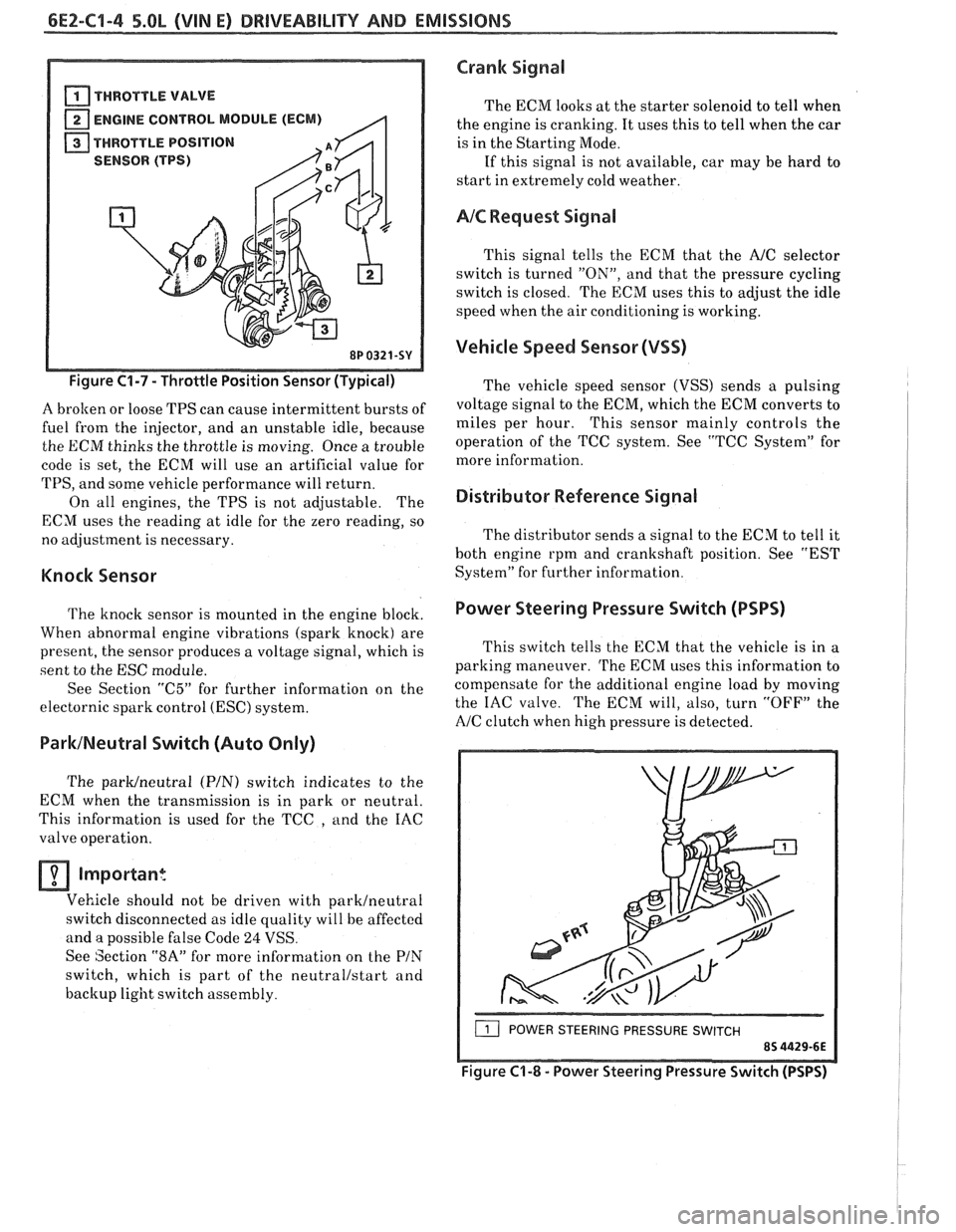
Figure C1-7 - Throttle Position Sensor (Typical)
A brolten or loose TPS can cause intermittent bursts of
fuel from the injector, and an unstable idle, because
the ECM thinks the throttle is moving. Once a trouble
code is set, the ECM will use an artificial value for
TPS, and some vehicle performance will return.
On all engines, the TPS is not adjustable. The
ECM uses the reading at idle for the zero reading, so
no adjustment is necessary.
Knock Sensor
The knock sensor is mounted in the engine block.
When abnormal engine vibrations (spark knock) are
present, the sensor produces a voltage signal, which is
sent to the ESC module.
See Section
"C5" for further information on the
electornic spark control
(ESC) system.
ParklNeutral Switch (Auto Only)
The parWneutra1 (PIN) switch indicates to the
ECM when the transmission is in park or neutral.
This information is used for the TCC
, and the IAC
valve operation.
Important
Vehicle should not be driven with parklneutral
switch disconnected as idle quality will be affected
and a possible false Code
24 VSS.
See Section
"8A" for more information on the PIN
switch, which is part of the neutrallstart and
backup light switch assembly.
Crank Signal
The ECM looks at the starter solenoid to tell when
the engine is cranking. It uses this to tell when the car
is in the Starting Mode.
If this signal is not available, car may be hard to
start in extremely cold weather.
AIC Request Signal
This signal tells the ECM that the AJC selector
switch is turned
"ON", and that the pressure cycling
switch is closed. The ECM uses this to adjust the idle
speed when the air conditioning is working.
Vehicle Speed Sensor (VSS)
The vehicle speed sensor (VSS) sends a pulsing
voltage signal to the ECM, which the ECM converts to
miles per hour. This sensor mainly controls the
operation of the TCC system. See "TCC System" for
more information.
Distributor Reference Signal
The distributor sends a signal to the ECM to tell it
both engine rpm and crankshaft position. See "EST
System" for further information.
Power Steering Pressure Switch (PSPS)
I
This switch tells the ECM that the vehicle is in a
parking maneuver.
The ECM uses this information to
compensate for the additional engine load by moving
the IAC valve. The ECM will, also, turn
"OFF" the
A/C clutch when high pressure is detected.
( POWER STEERING PRESSURE SWITCH
Figure C'I-8 - Power Steering Pressure Switch (PSPS)