1988 PONTIAC FIERO check engine
[x] Cancel search: check enginePage 1612 of 1825
INSTRUMENT PANEL, GAGES & CONSOLE 8C-'I
SECTION 8C
NSTRUMENT PANEL, GAGES & CONSOLE
CONTENTS
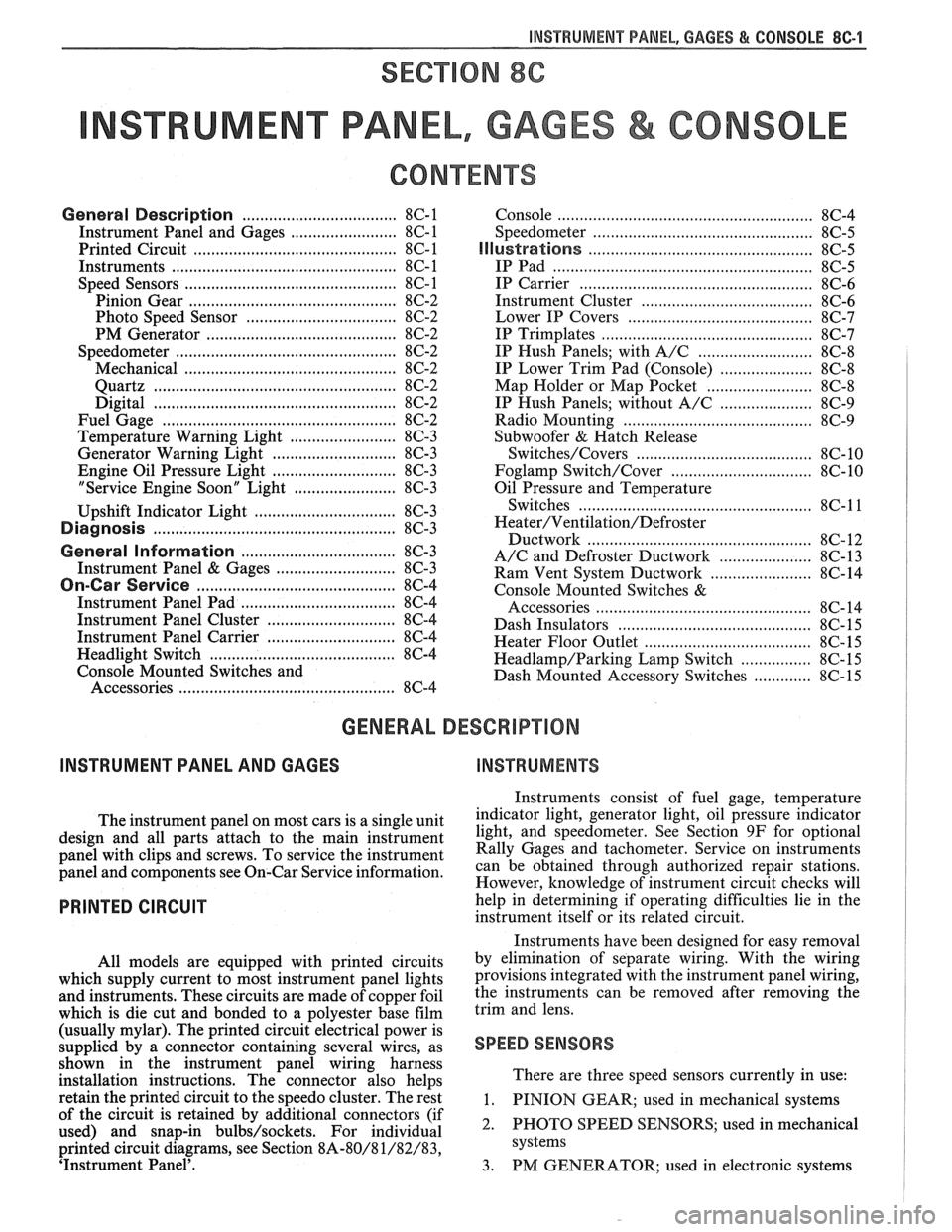
General Description ................................... 8C-1
Instrument Panel and Gages ........................ 8C-1
Printed Circuit .......................................... 8C-1
Instruments ................................................... 8C- 1
Speed Sensors
............................ .. ............. 8C- 1
Pinion Gear
............................................. 8C-2
Photo Speed Sensor ................................ 8C-2
PM Generator ................... .. ...... ............... 8C-2
Speedometer ................................................ 8C-2
Mechanical ....................... .. .................... 8C-2
Quartz ........................ .. .......................... 8C-2
Digital .................... .. ...... ................. 8C-2
Fuel Gage .................................................... 8C-2
Temperature Warning Light ...................... 8C-3
Generator Warning Light ............................ 8C-3
Engine Oil Pressure Light ............................ 8C-3
"Service Engine Soon" Light ....................... 8C-3
Upshift Indicator Light .............................. 8C-3
Diagnosis .................... .. ........................... 8C-3
General Information .................................. 8C-3
Instrument Panel & Gages ...................... ..... 8C-3
On-Car Service ......................... .. ........... 8C-4
Instrument Panel Pad ................................... 8C-4
Instrument Panel Cluster ........................... 8C-4
Instrument Panel Carrier ............................. 8C-4
Headlight Switch .......................................... 8C-4
Console Mounted Switches and
Accessories
............................................... 8C-4
Console ......................................................... 8C-4
Speedometer .................................................. 8C-5
Illustra3ions ................................................. 8C-5
IP Pad ........................................................... 8C-5
IP Carrier ................................................... 8C-6
Instrument Cluster ....................................... 8C-6
Lower IP Covers ......................................... 8C-7
IP Trimplates ............................................... 8C-7
IP Hush Panels; with A/C .......................... 8C-8
..................... IP Lower Trim Pad (Console) 8C-8
Map Holder or Map Pocket ........................ 8C-8
IP Hush Panels; without A/C ..................... 8C-9
Radio Mounting ........................................... 8C-9
Subwoofer & Hatch Release
Switches/Covers ........................................ 8C- 10
Foglamp Switch/Cover ................................ 8C- 10
Oil Pressure and Temperature
Switches
..................................................... 8C-11
Heater/Ventilation/Defroster
Ductwork .................................................. 8C- 12
A/C and Defroster Ductwork ..................... 8C-13
Ram Vent System Ductwork ....................... 8C-14
Console Mounted Switches
&
Accessories ................................................. 8C- 14
Dash Insulators
............................................ 8C- 15
Heater Floor Outlet
..................................... 8C-15
................ Headlamp/Parking Lamp Switch 8C- 15
............. Dash Mounted Accessory Switches 8C- 15
GENERAL DESCRIPTION
INSTRUMENT PANEL AND GAGES
INSTRUMENTS
Instruments consist of fuel gage, temperature
The instrument panel on most cars is a sing,e unit indicator light, generator light, oil pressure indicator
design and all parts attach to the main instrument light, and speedometer. See Section 9F for optional
panel with clips and screws. To service the instrument Gages and tachometer. Service on instruments
panel and components see on-car service information, can be obtained through authorized repair stations.
However, knowledge of instrument circuit checks will
PRINTED CIRCUIT
All models are equipped with printed circuits
which supply current to most instrument panel lights
and instruments. These circuits are made of copper foil
which is die cut and bonded to a polyester base film
(usually mylar). The printed circuit electrical power is
supplied by a connector containing several wires, as
shown in the instrument panel wiring harness
installation instructions. The connector also helps
retain the printed circuit to the speedo cluster. The rest
of the circuit is retained by additional connectors (if
used) and snap-in
bulbs/sockets. For individual
printed circuit diagrams, see Section
8A-80/8 1/82/83,
'Instrument Panel'. help
in determining if operating difficulties lie in the
instrument itself or its related circuit.
Instruments have been designed for easy removal
by elimination of separate wiring. With the wiring
provisions integrated with the instrument panel wiring,
the instruments can be removed after removing the
trim and lens.
SPEED SENSORS
There are three speed sensors currently in use:
1. PINION GEAR; used in mechanical systems
2. PHOTO SPEED SENSORS; used in mechanical
systems
3. PM GENERATOR; used in electronic systems
Page 1614 of 1825
INSTRUMENT PANEL. GAGES & CONSOLE 8C-3
tank only when ignition switch is turned to "ON" or
"ACCESSORY" positions.
When ignition is turned to "OFF" or "START"
positions, the pointer may come to rest at any position.
The letters
"E" and "F" on the fuel gage are used to
point out direction of indicator travel only.
TEMPERATURE WARNING LIGHT
The engine temperature warning light is
controlled by a thermal switch which senses engine
coolant temperatures.
When the ignition switch is turned to "START"
position, a test circuit is closed and the light will come
on to indicate whether the light is functioning properly.
It is important to note that with low boiling-point
coolants (such as plain water) the temperature light
may not come on even though the coolant is boiling.
GENERATOR WARNING LIGHT
The generator warning light, located in the
instrument cluster, should come on when the ignition
switch is turned
"ON" and engine is not running. If
not, either the bulb is burned out or wiring to generator
has an open circuit.
When the generator voltage output becomes
greater than the battery voltage, the
"GEN" light
should go out. This does not, however, indicate
whether the battery is being charged or if the voltage
regulator is functioning properly.
Checks of the charging system are covered in
Section 6D, 'Engine Electrical'.
ENGINE OIL PRESSURE LIGHT
The engine oil pressure warning light is mounted
in the instrument cluster and controlled by a pressure
operated switch located on the engine block. When the ignition switch is
in the
"run" or "start9' position, the
oil pressure light should come on. If not, the bulb is
burned out, there is an open circuit between the bulb
and the oil pressure switch, or there is an open circuit
between the oil pressure switch and the choke heater.
After the engine is running, the oil pressure light
should go out when the oil pressure reaches the correct
specification. If not an oil pressure problem, a faulty oil
pressure switch or an open circuit from the choke
heater fuse to the oil pressure switch is indicated.
"SERVICE ENGINE SOON" LIGHT
All cars have a "SERVICE ENGINE SOON"
light mounted in the instrument cluster. The
"SERVICE ENGINE SOON9' light should come on
during engine starting. The light may stay on
a short
time after the engine starts.
If the light comes on while
driving, service to the emission control system may be
required. See Section
6E and Section 8A-80,
'Instrument Cluster', for complete diagnosis and
wiring diagrams of the
""P;RVICE ENGINE SOON"
light circuit.
UPSHIFT INDICATOR LIGHT
If your vehicle has a manual transmission, there
may be an
''Upshift" light on the instrument panel.
This light is illuminated to indicate optimum shift
points throughout the range from optimum fuel
economy to optimum performance. When this light is
on, shift your transmission to the next higher gear
range if conditions permit. For fuel economy,
accelerate slowly and shift when the light goes on. For
performance, accelerate as desired and shift when the
light goes on.
Safe operation of the vehicle may require shifting
differently than indicated by the "Upshift" light to
adapt to weather, road or traffic conditions.
Downshifting one or more gears may be required
to keep the engine running smoothly or to maintain
satisfactory performance.
DIAGNOSIS
Diagnostic information for all instrument panel
electrical systems is found in Section
8A-80,
'Instrument Panel'.
CAUTION: When removing or
installing any electrical units,
disconnect the negative battery cable
to prevent possible short circuits
which could lead to personal injury
and/or property damage. When
replacing a speedometer or
odometer assembly, the law requires the
odometer reading of the replacement unit to
be set to register the same mileage as the
prior odometer.
if the same mileage cannot be
set, the
law requires that the replacement
odometer be set to zero and a label be
installed on the driver's door frame to show
the previous odometer reading and the date
of replacement.
GENERAL BNFORMATlOM
INSTRUMENT PANEL AND GAGES
The instrument panel is a single unit design and
and screws. To service the instrument panel and
all parts attach to the main instrument panel with clips components see Figs. 601 through 610.
Page 1651 of 1825
9A-2 RADlO SYSTEMS - AND ANTENNAS
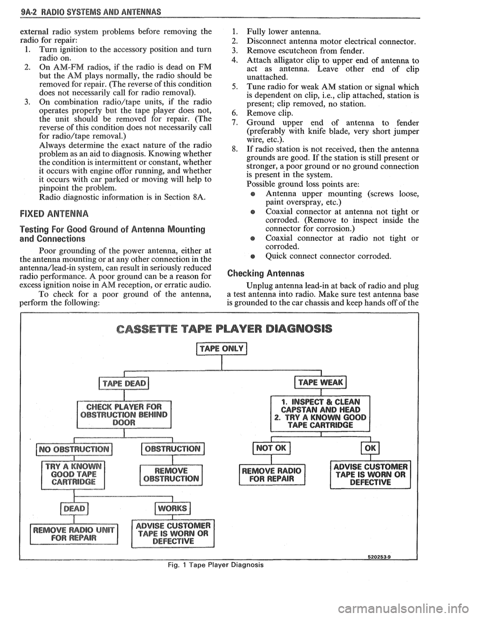
external radio system problems before removing the
radio for repair:
1. Turn ignition to the accessory position and turn
radio on.
2. On AM-FM radios, if the radio is dead on FM
but the AM plays normally, the radio should be
removed for repair. (The reverse of this condition
does not necessarily call for radio removal).
3. On combination radio/tape units, if the radio
operates properly but the tape player does not,
the unit should be removed for repair. (The
reverse of this condition does not necessarily call
for
radio/tape removal.)
Always determine the exact nature of the radio
problem as an aid to diagnosis. Knowing whether
the condition is intermittent or constant, whether
it occurs with engine
offor running, and whether
it occurs with car parked or moving will help to
pinpoint the problem.
Radio diagnostic information is in Section
8A.
FIXED ANTENNA
Testing For Good Ground of Antenna Mounting
and Connections
Poor grounding of the power antenna, either at
the antenna mounting or at any other connection in the
antenna/lead-in system, can result in seriously reduced
radio performance.
A poor ground can be a reason for
excess ignition noise in
AM reception, or erratic audio.
To check for a poor ground of the antenna,
perform the following:
1. Fully lower antenna.
2. Disconnect antenna motor electrical connector.
3. Remove escutcheon from fender.
4. Attach alligator clip to upper end of antenna to
act as antenna. Leave other end of clip
unattached.
5. Tune radio for weak AM station or signal which
is dependent on clip,
i.e., clip attached, station is
present; clip removed, no station.
6. Remove clip.
7. Ground upper end of antenna to fender
(preferably with knife blade, very short jumper
wire, etc.).
8. If radio station is not received, then the antenna
grounds are good. If the station is still present or
stronger, a poor ground or no ground connection
is present in the system.
Possible ground loss points are:
s Antenna upper mounting (screws loose,
paint overspray, etc.)
e coaxial connector at antenna not tight or
corroded. (Remove to inspect inside the
connector for corrosion.)
e Coaxial connector at radio not tight or
corroded.
e Quick connect connector corroded.
Checking Antennas
Unplug antenna lead-in at back of radio and plug
a test antenna into radio. Make sure test antenna base
is grounded to the car chassis and keep hands off of the
CASSEmE TAPE PLAYER DIAGNOSIS
1. INSPECT I& CLEAN
CAPSTAN
AND HEAD . TRY A KNOWN 600
ADVISE CUSTOMER
TAPE IS WORN QR DEFECTIVE
Fig. 1 Tape Player Diagnosis
Page 1667 of 1825
VACUUM SUPPLY
Tht vacuum to operate the Cruise Control servo
can come from: manifold vacuum connected straight
to the servo, from manifold through a vacuum storage
tank, or straight from a vacuum pump. For specific
vacuum routing, see On-Car Service.
ELECTRICAL AND VACUUM RELEASE
SWITCHES
These switches are used to disengage the cruise
control system. An electrical release switch mounted
on the brake pedal bracket (and clutch pedal bracket
on cars equipped with manual transaxle) disengages
the system electrically when the brake (or clutch) pedal is
depressed. This is done by interrupting the flow of
current to the controller. A vacuum release valve
mounted on the brake pedal bracket vents the trapped
vacuum in the servo to atmosphere when the brake
pedal is depressed, allowing the servo unit to more
quickly return the throttle to idle position. This is done
by routing a separate hose directly to the servo from
the normally closed vacuum switch. These two types
of switches will also sometimes be combined with stop
light switch, TCC switch, or other switches. For
specific usage and adjustment of these switches, see
On-Car Service.
ELECTRICAL HARNESS
For specific wiring and connector locations, see
Section
8A-34, 'Cruise Control'.
Improper operation can be caused by one or a
CRUISE SYSTEM SURGES t combination of mechanical, electrical and vacuum The servo and throttle linkages should operate problems. In resolving any cruise system operating
problem, first make a visual inspection. Check the freely
and smoothly. This linkage should be
system to ensure there are no bare, broken, or adjusted
as described in the On-Car Service
disconnected wires or any pinched, damaged,
-or portion of this section.
disconnected vacuum hoses. The servo and throttle
e Check hose routing for pinches, leaks or
linkage should operate freely and smoothly. The servo restrictions.
(See vacuum schematics in the
linkage should be adjusted as described in the On-Car On-Car
Service portion of this section).
Service portion of this section. See
Section
8A-34, 'Cruise Control'.
CRUISE SET SPEED HIGH OR LOW
Since any problem in this system is either
vacuum, mechanical, or electrical, the technician
should perform a few initial checks before turning to
Section
8A. This can be done by first eliminating a
vacuum or mechanical problem by starting the engine
and using finger to feel for source vacuum at the servo,
and by visual inspection of vacuum release valve,
throttle linkage, vacuum hoses, etc. If preliminary
inspection reveals no solution and the system is
inoperative, use the diagnostic information in Section
8A-34, 'Cruise Control'.
Several versions of a quick check instrument
similar to tool 5-34185 are available. This quick check
instrument is installed in place of the controller and
determines which part of the system has a problem.
Instructions on the operation of the instrument will be
provided with the unit. Check vacuum hoses for
proper routing,
restrictions or leaks. Adjust or replace as
required. (See vacuum schematics in the On-Car
Service portion of this section.)
e Check servo linkage for excess slack and adjust
as described in the On-Car Service portion of this
section.
s If no system problem is noted, replace the
electronic controller (module).
EXCESSIVE CRUISE SPEED LOSS ON HILLS
e Check hoses for vacuum leaks. (See vacuum
schematics in the On-Car Service portion of this
section).
e Determine if check valve is functional (where
applicable).
CRUISE TAP-UP & TAP-DOWN
If all other functions of cruise control are working
except "tap-up" and "tap-down" the controller
(module) is at fault.
Page 1675 of 1825
9G-2 MISCELLANEOUS ACCESSORIES
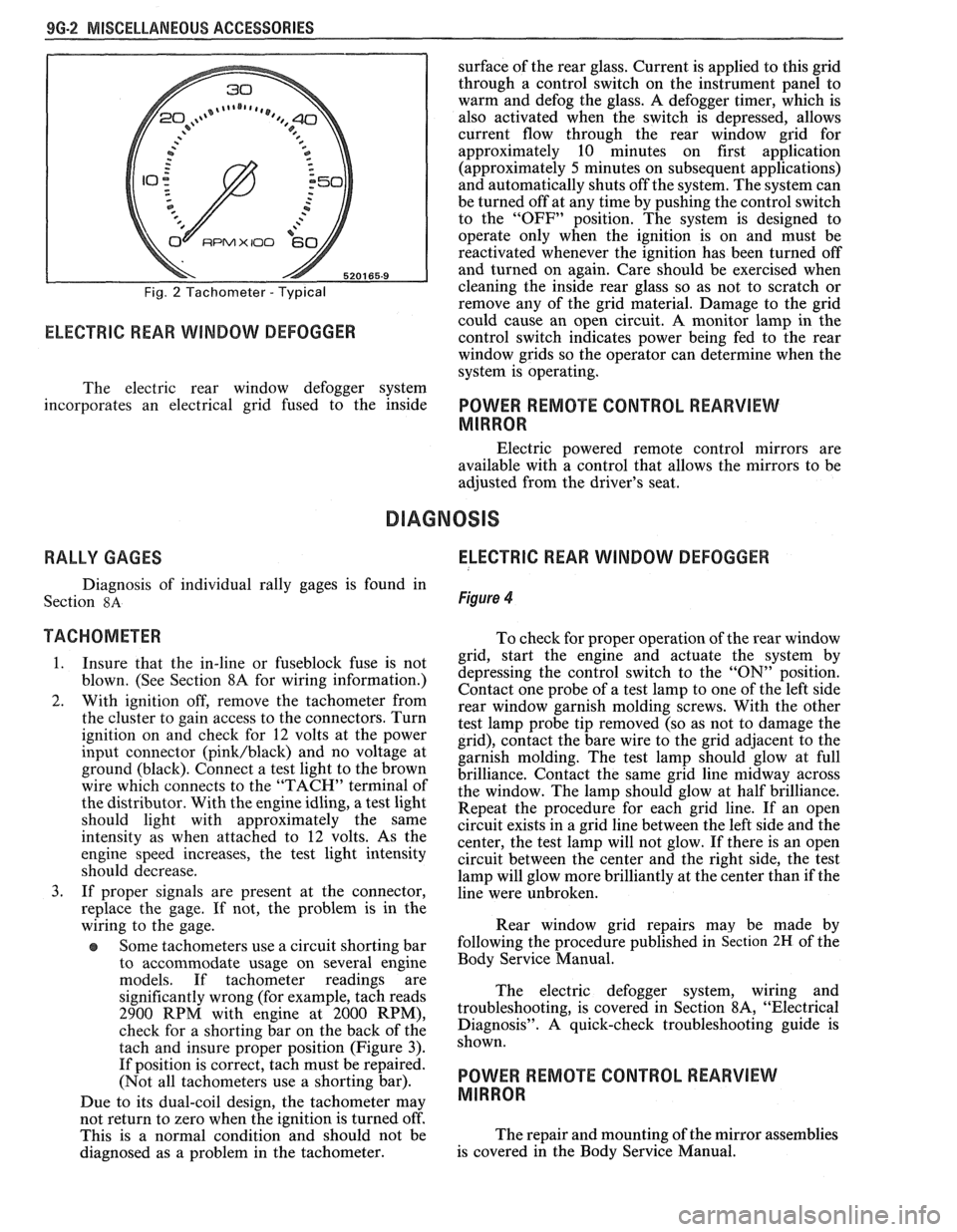
Fig. 2 Tachometer - Typical
RPMX I00 €31-
ELECTRIC REAR WINDOW DEFOGGER
surface of the rear glass. Current is applied to this grid
through a control switch on the instrument panel to
warm and defog the glass. A defogger timer, which is
also activated when the switch is depressed, allows
current flow through the rear window grid
for
approximately 10 minutes on first application
(approximately
5 minutes on subsequent applications)
and automatically shuts off the system. The system can
be turned off at any time by pushing the control switch
to the "OFF" position. The system is designed to
operate only when the ignition is on and must be
reactivated whenever the ignition has been turned off
and turned on again. Care should be exercised when
cleaning the inside rear glass so as not to scratch or
remove any of the grid material. Damage to the grid
could cause an open circuit. A monitor lamp in-the
control switch indicates power being fed to the rear
window grids so the operator can determine when the
system is operating.
The electric rear window defogger system
incorporates an electrical grid fused to the inside
POWER REMOTE CONTROL REARVIEW
MIRROR
Electric powered remote control mirrors are
available with a control that allows the mirrors to be
adjusted from the driver's seat.
RALLY GAGES ELECTRIC REAR WINDOW DEFOGGER
Diagnosis of individual rally gages is found in
Section
8A Figure 4
TACHOMETER To check for moper o~eration of the rear window
1. Insure that the in-line or fuseblock fuse is not
blown. (See Section 8A for wiring information.)
2. With ignition off, remove the tachometer from
the cluster to gain access to the connectors. Turn
ignition on and check for
12 volts at the power
input connector
(pink/black) and no voltage at
ground (black). Connect a test light to the brown
wire which connects to the "TACH" terminal of
the distributor. With the engine idling, a test light
should light with approximately the same
intensity as when attached to
12 volts. As the
engine speed increases, the test light intensity
should decrease.
3. If proper signals are present at the connector,
replace the gage. If not, the problem is in the
wiring to the gage.
Some tachometers use a circuit shorting bar
to accommodate usage on several engine
models. If tachometer readings are
significantly wrong (for example, tach reads
2900 RPM with engine at 2000 RPM),
check for a shorting bar on the back of the
tach and insure proper position (Figure
3).
If position is correct, tach must be repaired.
(Not all tachometers use a shorting bar).
Due to its dual-coil design, the tachometer
may
- grid, start the engine a& actuate the system by
depressing the control switch to the
"ON" position.
Contact one probe of a test lamp to one of the left side
rear window garnish molding screws. With the other
test lamp probe tip removed (so as not to damage the
grid), contact the bare wire to the grid adjacent to the
garnish molding. The test lamp should glow at full
brilliance. Contact the same grid line midway across
the window. The lamp should glow at half brilliance.
Repeat the procedure for each grid line. If an open
circuit exists in a grid line between the left side and the
center, the test lamp will not glow. If there is an open
circuit between the center and the right side, the test
lamp will glow more brilliantly at the center than if the
line were unbroken.
Rear window grid repairs may be made by
following the procedure published in
Section 2H of the
Body Service Manual.
The electric defogger system, wiring and
troubleshooting, is covered in Section
8A, "Electrical
Diagnosis". A quick-check troubleshooting guide is
shown.
POWER REMOTE CONTROL REARVIEW
MIRROR
not return to zero when tvhe ignition is turned off'.
This is a normal condition and should not be The
repair and mounting of the mirror assemblies
diagnosed as a problem in the tachometer. is
covered in the Body Service Manual.
Page 1682 of 1825
GENERAL INFORMATION - F STYLE 1 H-1
SECTION IH
GENERAL NFORMAT
NOTICE: The anti-theft label found on some major sheet metal, engines, and transmissions must be masked
prior to painting, rustproofing, undercoating, etc. The mask
must be removed following the above operations.
Failure to keep the label clean and readable may result in liability for violation of Federal Vehicle Theft Prevention
Standard, and subject the vehicle owner to possible suspicion that the part was stolen.
Lock Cylinder Coding
..................................... I H-1 Chip Resistant Plastisol Material .................... 1 H-8
...................................................... Lubrication 1 H-2 Flexible Exterior Plastic Parts ......................... 1H-9
Adhesive Body Side Moldings ......................... 1H-3 Metal Replacement Parts Finishing ................ lH-13
Waterleak Diagnosis and Repair ..................... 1H-3 Interior Plastic Trim Parts Finishing .............. 1H-13
.................................................... Anticorrosion Treatment ................................ IH-4 Special Tools I H- 14
LOCK CYL!NDER CODING o Check key operation in the lock cylinder.
KEY IDENTIFICATION AND USAGE
REPLACEMENT LOCK CYLINDERS
The lock cylinder keyway is designed so that
other model keys will not enter a current model lock
cylinder. Two noninterchangeable keys are used.
CB Square headed key is used in the ignition lock
cylinder.
o Oval headed key is used in all other lock
cylinders.
Key identification is obtained from the four
character key code stamped on the knockout portion
of the key head and an identification letter stamped on
the key shank. After the code number has been
recorded by the owner, the plugs should be knocked
out of the key head. From these numbers, the lock
combination can be determined by use of a code list
(available to owners of key cutting equipment from
equipment suppliers). If key code numbers are not
available from records or from the knockout plug, the
lock combination (tumbler numbers and position) can
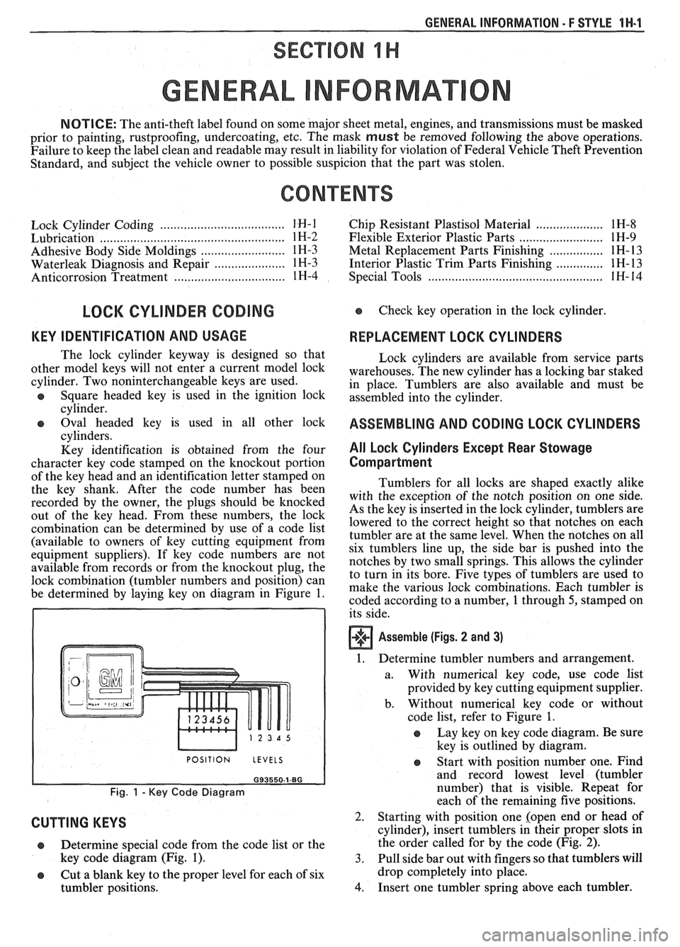
be determined by laying key on diagram in Figure
1.
I POSITION LEVELS I
Fig. 1 - Key Code Diagram
CUTTING KEYS
Lock cylinders are available from service parts
warehouses. The new cylinder has a locking bar staked
in place. Tumblers are also available and must be
assembled into the cylinder.
ASSEMBLING AND CODING LOCK CYLINDERS
All Lock Cylinders Except Rear Stowage
Compartment
Tumblers for all locks are shaped exactly alike
with the exception of the notch position on one side.
As the key is inserted in the lock cylinder, tumblers are
lowered to the correct height so that notches on each
tumbler are at the same level. When the notches on all
six tumblers line up, the side bar is pushed into the
notches by two small springs. This allows the cylinder
to turn in its bore. Five types of tumblers are used to
make the various lock combinations. Each tumbler is
coded according to a number,
1 through 5, stamped on
its side.
Assemble (Figs. 2 and 3)
1. Determine tumbler numbers and arrangement.
a. With numerical
key code, use code list
provided by key cutting equipment supplier.
b. Without numerical
key code or without
code list, refer to Figure
1.
o Lay key on key code diagram. Be sure
key is outlined by diagram.
Determine special code from the code list or the
key code diagram (Fig.
1). 3.
o Cut a blank key to the proper level for each of six
tumbler positions.
4.
Start with position number one. Find
and record lowest level (tumbler
number) that is visible. Repeat for
each of the remaining five positions.
Starting with position one [open end or head of
cylinder), insert tumblers in their proper slots in
the order called for by the code (Fig.
2).
Pull side bar out with fingers so that tumblers will
drop completely into place.
Insert one tumbler spring above each tumbler.
Page 1703 of 1825
2H-6 STATIONARY GLASS - F STYLE
all traces of factory installed adhesive must be
removed prior to reinstallation.
5. Wipe sanded mirror support with clean paper
towel saturated with alcohol and allow to dry.
6. Follow directions on manufacturer's kit to
prepare
rearview mirror support prior to
installation on glass.
7. Properly position support to its premarked
location, with rounded end pointed upward; press
support against glass for 30 to 60 seconds,
exerting steady pressure against glass. After five
minutes, any excess adhesive may be removed
with an alcohol moistened paper towel or glass
cleaning solution.
8. Reinstall mirror
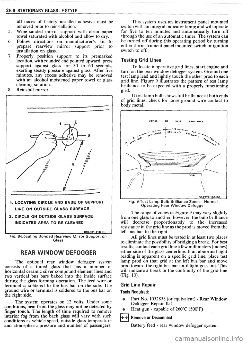
4. LOCATING CIRCLE AND BASE OF SUPPORT
LINE ON OUTSIDE GLASS SURFACE
2. CIRCLE ON OUTSIDE GLASS SURFACE
INDICATES AREA TO BE CLEANED
G94301-11 B.BG
Fig. 8-Locating Bonded earv view Mirror Support on
Glass
REAR WlMBOW DEFOGGER
The optional rear window defogger system
consists of a tinted glass that has a number of
horizontal ceramic silver compound element lines and
two vertical bus bars baked into the inside surface
during the glass forming operation. The feed wire or
terminal is soldered to the bus bar on the side. The
ground wire or terminal is soldered to the bus bar on
the right side.
The system operates on 12 volts. Under some
conditions, heat from the glass may not be detected by
finger touch. The length of time required to remove
interior fog from the back glass will vary with such
conditions as vehicle speed, outside glass temperature
and atmospheric pressure and number of passengers. This
system uses an instrument panel mounted
switch with an integral indicator lamp; and will operate
for five to ten minutes and automatically turn off
through the use of an automatic timer. The system can
be turned off during this operating period by turning
either the instrument panel mounted switch or ignition
switch to off.
Testing Grid Lines
To locate inoperative grid lines, start engine and
turn on the rear window defogger system. Ground one
test lamp lead and lightly touch the other prod to each
grid line. Figure
9 illustrates the pattern of test lamp
brilliance to be expected with a properly functioning
grid.
If test lamp bulb shows full brilliance at both ends
of grid lines, check for loose ground wire contact to
body metal.
Fig. 9-Test Lamp Bulb Brilliance Zones - Normal
Operating Rear Window Defogger
The range of zones in Figure 9 may vary slightly
from one glass to another; however, the bulb brilliance
will decrease proportionately to the increased
resistance in the grid line as the prod is moved from the
left bus bar to the right.
All grid lines must be tested in at least two places
to eliminate the possibility of bridging a break. For best
results, contact each grid line a few millimeters (inches)
either side of the glass centerline. If an abnormal light
reading is apparent on a specific grid line, place test
lamp prod on that grid at the left bus bar and move
prod toward the right bus bar until light goes out. This
will indicate a break in the continuity of the grid line
(Fig.
10).
Grid Line Repair
Tools Required:
o Part No. 1052858 (or equivalent) - Rear Window
Defogger Repair Kit
e Heat gun - capable of 260°C (500°F)
Remove or Disconnect
Battery 'feed - rear window defogger system
Page 1706 of 1825
UNDERBODY-F STYLE 3H-1
SECTION 3H
UNDERBODY
CONTENTS
General Body Construction .......................................................................................................... 3H- 1
Alignment Checking ................................................................................................................ 3H- I
Floor Pan Insulators ...................... .. ........................................................................................ 3H- 1
Floor Carpets ................................................................................................................................. 3H-2
metric-to-English dimensional conversion data.
Dimensions to gage holes are measured to dead center
GENERAL BODY CONSTRUCTION of the holes and flush to adjacent surface metal unless
Information in this section pertains to unitized otherwise specified.
body construction which
incorporates integral front
and rear frame side rails. FLOOR PAN INSULATORS
Consideration must be given when checking
underbody dimensions. The engine front suspension
lower control arms are supported by a cross member.
The cross member, in turn, is bolted to the body at six
locations
-- three on each side of the engine front
compartment lower rails. Mounting provisions for the
front suspension system are shared by chassis
components (suspension lower control arms and cross
member) and body components (engine compartment
side panels). The suspension strut towers must be
dimensionally correct in relation to the remainder of
the underbody in order to maintain specified
suspension strut and
castedcamber angles.
Since the individual underbody components also
contribute directly to the overall strength of the body,
it is essential that proper welding techniques be
observed during service repair operations. The
underbody components should be properly sealed and
rustproofed whenever body repair operations destroy
or damage the original sealing and rustproofing. When
rustproofing critical underbody components, it is
essential that a good quality type of air dry primer be
used (such as corrosion resistant chromate or
equivalent material). It is not advisable to use
combination type primer-surfacers.
ALIGNMENT CHECKING
An accurate method of determining the
alignment of the underbody utilizes a measuring tram
gage. The tram gage set required to perform the
recommended measuring checks must include a
vertical pointer capable of reaching 914 mm (36").
Two types of measurements can be made with
a
tram gage: direct point-to-point measurements and
measurements calculated on a horizontal
vlane (datum
line) parallel to the underbody. In the
latter case, the
vertical pointers must be set as specified for each point
to be measured (Fig. 3-1).
Point-to-point measurements are generally taken
only on engine compartment components (Fig. 3-2)
and simply require the vertical pointers to be equally
set.
Figure #3-3 describes the alphabetically
identified points of measurement. Figure 3-4 provides Floor
pan insulators have been designed for the
higher floor pan temperatures that result from the use
of the catalytic converter in the exhaust system.
Therefore, when servicing a vehicle in the field, it is
essential that any insulators that may have been
disturbed or removed be reinstalled in the original
sequence and location. Also, if it becomes necessary to
replace an insulator, the material specified for that
particular location on the floor pan must be used. The
types of materials are listed below. Items 1 and
2 are
rolled stock and are ordered by linear foot and cut to
fit.
1. Insulator floor pan
(cerra blanket thermal) -
consists of 10 mm (3/8") thick aluminum silica
(type 1).
2. Insulator floor pan (amberlite) - consists of 10
mm
(3/8") thick resinated fibers (type 2).
3. Insulator floor pan sheet (phenolic bonded fiber
glass)
305 mm x 457 mm (12" x 18") cut to size,
(type 3).
All of the above materials must meet
Motor Vehicle Safety Standard No. 302 for
flammability.
When servicing or replacing interior insulators,
the following instructions must be observed:
1. Insulators must be installed in the original
position and sequence. Pieces should be butted
together in order to avoid gapping or
overlapping.
2. If it is necessary to replace an insulator, the
specified material must be used.
3. Use original
part to determine the amount of
replacement material required and as a template
for cutting and fitting the new piece to the floor
pan.
4. When installing insulator, do not enlarge cutouts
or holes that are used for the attachment of
interior components such as seats or seat belts.
5. Cross body harnesses for interior components
such as power seats, lap belt warning light and
buzzer or rear speakers must be routed over the
floor pan insulators in the original location and
clipped in place.