1988 PONTIAC FIERO light
[x] Cancel search: lightPage 1371 of 1825
AIR CONDITIONING: BLOWER CONTROLS
TROUBLESHOOTING NlNTS
a Try the following checks before doing the
System Diagnosis
.
1 . Check the HTR A/C Fuse by visual inspection .
2 . Check that 6112 is clean and tight .
3 . Check that Blower Motor connectors and
Blower Relay are mated correctly and firmly
seated
.
a Go the the AIC Systern Check in 813-62 for a
guide to normal operation
.
Go to Systern Diagnosis in this section for
diagnostic tests
.
SYSTEM DIAGNOSIS
Do the tests listed for your symptom in the
Symptom Table below
.
Tests follow the Symptom Table .
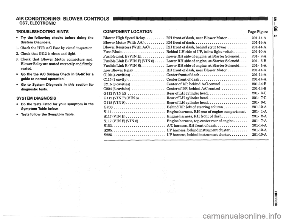
COMPONENT LOCATION Page-Figure
Blower High Speed Relay
.......... RH front of dash. near Blower Motor ..........
Blower Motor (With AIC) .......... RH front of dash ...........................
Blower Resistors (With AIC) ....... RH front of dash. behind strut tower ..........
...................... Fuse Block
Behind LH side of IIP. below light switch .......
............ Fusible Link B (VIN E) Lower RH side of engine. at Starter Solenoid ....
Fusible Link B (VIN F) (VIN 8) ..... Lower RH side of engine. at Starter Solenoid ....
............ Fusible Link B (VIN S) Lower RN side of engine. at Starter Solenoid ....
................ Low Blower Relay RH front of dash. near Blower Motor ..........
........................ ................. C102 (4 cavities) Center
front of dash
................... ........................ C115 (1 cavity) Center
front of dash
................. ............. C215 (3 cavities) Center
of IIP. behind AlC control
................. ............. 6224 (6 cavities) Center
of IIP. behind Ale control
................... .................... 6112 (VIN E) Rear of LH cylinder head
............. .................... 6112 (VIN F) (VIN 8) Rear of LH cylinder head
.................... .................... 6112 (VIN S) Rear
of LN cylinder head
.......................... ............ 6200 Behind I/P. left of steering column
........................... Slll Engine harness. RN rear of engine compartment
.................... ............. S117 (VIN E) Engine harness. RH front of dash
............. ....... S117 (VIN F) (VIN 8) Engine harness. top center rear of engine
........................... ................ S153 AIC harness. RH front of dash
........................... ......... S205 IIP harness. behind instrument cluster
........................... S225 IIP harness. behind instrument cluster .........
Page 1375 of 1825
AIR CONDITIONING: BLOWER CONTROLS
C67, ELECTRONIC
(Continued from previous page)
GRNIBLK (990) wire. If wire is good, do
Test
E.
5. Check for open in BRNNHT (64) wire. If
wire is good, do Test
E.
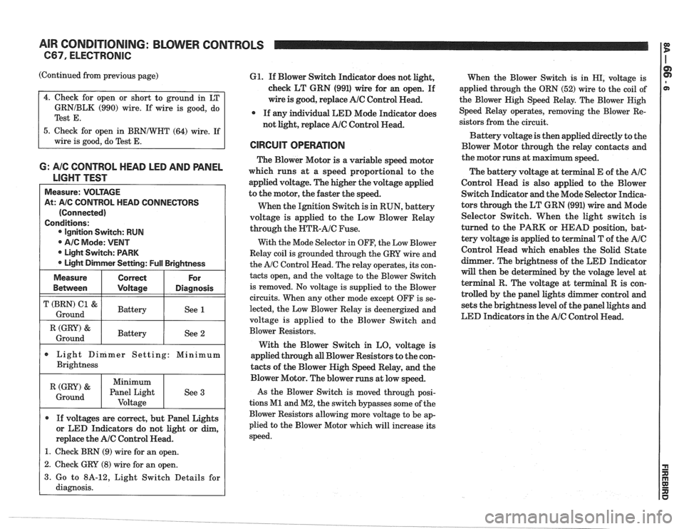
6: A/C CONTROL HEAD LED AND PANEL
LIGHT TEST
Measure: VOLTAGE
At:
A/C CONTROL HEAD CONNECTORS
(Connected)
Conditions: Ignition Switch: RUN
@ AIC Mode: VENT
* Light Switch: PARK
Light Dimmer Setting:
Full Brightness
I (GRY) & I Battery / See 2 1 Ground
Measure
Bemeen
T (BRN) C1 &
Ground
Light Dinimer Setting: Minimum
Brightness
Correct
Voltage
Battery
If voltages are correct, but Panel Lights
or LED Indicators do not light or dim,
replace the
AlC Control Head.
1. Check BRN (9) wire for an open.
For
Diagnosis
See 1
(GRY) '
Ground
61. If Blower Switch Indicator does not light,
check LT GRN (991) wire for an open. If
wire is good, replace
AlC Control Read.
* If any individual LED Mode Indicator does
not light, replace
AlC Control Head.
CIRCUIT OPERATION
The Blower Motor is a variable speed motor
which runs at a speed proportional to the
applied voltage. The higher the voltage applied
to the motor, the faster the speed.
When the Ignition Switch is
in RUN, battery
voltage is applied to the Low Blower Relay
through the
NTR-AIC Fuse.
With the Mode Selector in OFF, the Low Blower
Relay coil is grounded through the GRY wire and
the
A/C Control Head. The relay operates, its con-
tacts open, and the voltage to the Blower Switch
is removed. No voltage is supplied to the Blower
circuits. When any other mode except OFF is se-
lected, the Low Blower Relay is deenergized and
voltage is applied to the Blower Switch and
Blower Resistors.
With the Blower Switch in LO, voltage is
applied through
all Blower Resistors to the con-
tacts of the Blower High Speed Relay, and the
Minimum
Panel Light Voltage
- -
Blower Motor. The blower runs at low speed.
As the Blower Switch is moved through posi-
tions
M1 and M2, the switch bypasses some of the
Blower Resistors allowing more voltage to be ap-
plied to the Blower Motor which will increase its
speed.
See
3
When
the Blower Switch is in HI, voltage is
applied through the ORN (52) wire to the coil of
the Blower Nigh Speed Relay. The Blower Nigh
Speed Relay operates, removing the Blower Re-
sistors from the circuit.
Battery voltage is then applied directly to the
Blower Motor through the relay contacts and
the motor runs at maximum speed.
The battery voltage at
t
Control Read is also applied to the Blower
Switch Indicator and the Mode Selector Indica-
tors through the LT GRN (991) wire and Mode
Selector Switch. When the light switch is
turned to the PARK or HEAD position, bat-
tery voltage is applied to terminal T of the
AIC
Control Head which enables the Solid State
dimmer. The brightness of the LED Indicator
will then be det
terminal R. The volt
trolled by the panel
sets the brightness level of the panel lights and
LED Indicators in the
AIC Control Head.
1 2. Check GRY (8) wire for an open. I
3. Go to 8A-12, Light Switch Details for
diagnosis.
Page 1380 of 1825
AIR CONDITIONING: COMPRESSOR CONTROLS
C67. ELECTRONIC
TROUBLESHOOTING HINTS
Try the following checks before doing the
System Check
.
1 . Check CLSTR Fuse by visual inspection .
2 . Check that the A/C Compressor Clutch con-
nector is firmly seated
.
3 . Check that ground 6112 is clean and tight .
Go to System Check for a guide to normal
Compressor Control operation
.
o Go to System Diagnosis for Compressor Con-
trol diagnostic tests
.
SYSTEM CHECK
Complete the AIC System Check in Section
$A-62 as a guide to normal operation of the
AIC System .
Use the sy&esla Check Table as a guide to
normal operation
of the Compressor Control .
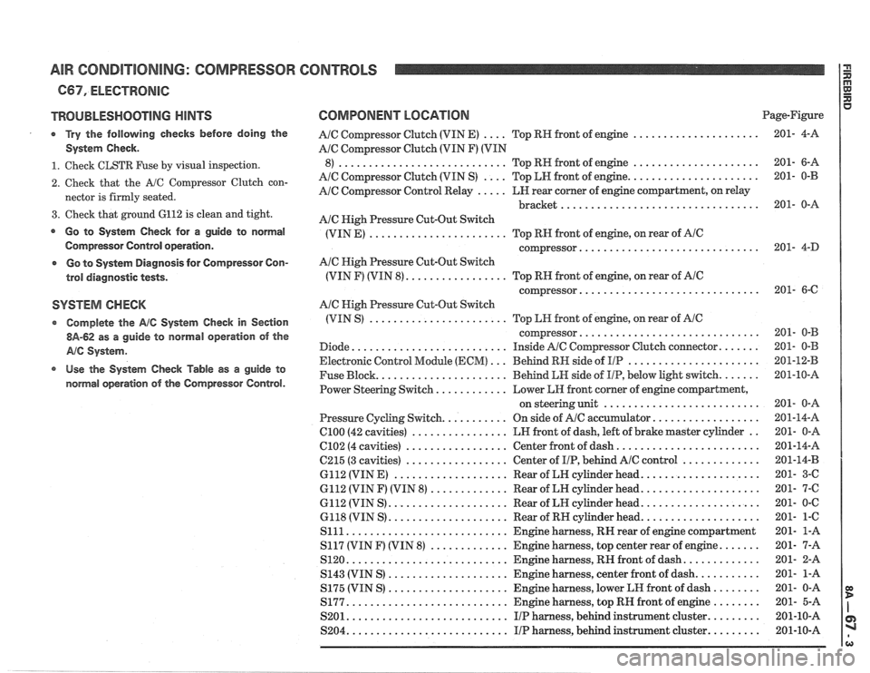
COMPONENT LOCATION Page-Figure
.... ..................... A/C Compressor Clutch (VIN E) Top
RH front of engine 201-
4-A
AIC Compressor Clutch (VIN F) (VIN
..................... ............................ 8) Top RN front of engine 201- 6-A
.... ...................... A/C Compressor Clutch (VIN S) Top LH front of engine 201-
0-B
A/C Compressor Control Relay ..... LN rear comer of engine compartment. on relay
................................. bracket 201- 0-A
Ale High Pressure Cut-Out Switch
(VIN E)
....................... Top RH front of engine. on rear of AIC
.............................. compressor 201- 4-D
AIC High Pressure Cut-Out Switch
(VIN F) (VIN 8)
................. Top RN front of engine. on rear of AlC
.............................. compressor 201- 6-C
A/C Nigh Pressure Cut-Out Switch
(VIN S)
....................... Top LH front of engine. on rear of AIC
.............................. coqressor 201- 0-B
Diode
.......................... Inside AIC Compressor Clutch connector ....... 201- 0-B
Electronic Control Module
(ECM) ... Behind RH side of I/P ...................... 201-12-B
Fuse Block
...................... Behind LH side of IIP. below light switch ....... 201-10-A
Power Steering Switch
............ Lower LH front comer of engine compartment.
.......................... on steering unit 201- 0-A
Pressure Cycling Switch
........... On side of Ale accumulator .................. 201-14-A
ClOO (42 cavities) ................ LN front of dash. left of brake master cylinder .. 201- 0-A
6102 (4 cavities) ................. Center front of dash ........................ 201-14-A
6215 (3 cavities) ................. Center of I/P. behind AlC control ............. 201-14-B
6112 (VIN E)
................... Rear of LH cylinder head .................... 201- 3-C
6112 (VIN F) (VIN 8)
............. Rear of LH cylinder head .................... 201- 7-6
6112 (VIN S) .................... Rear of LH cylinder head .................... 201- 0-C
6118 (VIN S)
.................... Rear of RH cylinder head .................... 201- 1-6
S111 ........................... Engine harness. RH rear of engine compartment 201-
1-A
S117 (VIN
F) (VIN 8) ............. Engine harness. top center rear of engine ....... 201- 7-A
S120
........................... Engine harness. RIP front of dash ............. 201- 2-A
S143 (VIN S)
.................... Engine harness. center front of dash ........... 201- 1-A
S175 (VIN S)
.................... Engine harness. lower LH front of dash ........ 201- 0-A
S177
........................... Engine harness. top RH front of engine ........ 201- 5-A
S201
........................... IIP harness. behind instrument cluster ......... 201-10-A
S204
........................... I/P harness. behind instrument cluster ......... 201-10-A
Page 1389 of 1825
AIR CONDITIONING: AIR DELIVERY I g
667, ELECTRONIC
TROUBLESHOOTING
HINTS
Try the following checks before doing System
Diagnosis.
1. Check for vacuum to the vacuum tank at the
BLACK Hose from the engine vacuum
source and at the VIOLET Rose to the
AIC
Vacuum Solenoid Module.
Check the operation of the Temperature
Valve by setting the Temperature Selector
to COLD and then moving it to ROT.
Observe that the valve moves through its
full range each time the Temperature Selec-
tor is changed from one end of the range to
the other. If the valve is not fully closing or
opening, check that the valve is free to move
and that none of the linkage is binding.
3. Check that Heater Water Bypass Valve
operates in MAX
AIC Mode.
Go to the AIC System Check in 8A-62 for a
guide to normal operation of the Air
Delvery
System.
Go to System Diagnosis
in this section for
diagnostic tests.
SYSTEM DIAGNOSIS
Engine warm and running at idle.
If air flow does not come from the proper
outlets under one or more operating modes,
at least one of the air valves is not moving to
the proper position.
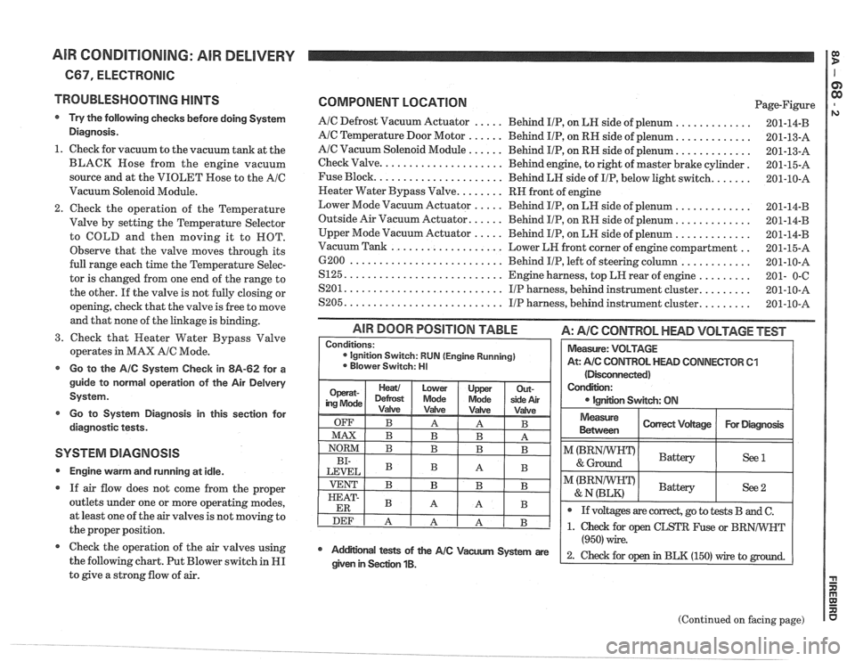
@ Check the operation of the air valves using
the following chart. Put Blower switch in
HI
to give a strong flow of air.
COMPONENT LOCATION Page-Figure
AIC Defrost Vacuum Actuator ..... Behind IIP, on LH side of plenum .............
AIC Temperature Door Motor ...... Behind IIP, on RH side of plenum. ............
AIC Vacuum Solenoid Module ...... Behind IIP, on RH side of plenum. ............
Check Valve. .................... Behind engine, to right of master brake cylinder.
Fuse Block.
..................... Behind LH side of IIP, below light switch. ......
Neater Water Bypass Valve. ....... RH front of engine
Lower Mode Vacuum Actuator
..... Behind IIP, on LH side of plenum .............
Outside Air Vacuum Actuator. ..... Behind IIP, on RH side of plenum. ............
Upper Mode Vacuum Actuator ..... Behind IIP, on LH side of plenum .............
.. Vacuum Tank ................... Lower LH front corner of engine compartment
6200
.......................... Behind IIP, left of steering column ............
S125. .......................... Engine harness, top LH rear of engine .........
........ S201. .......................... IIP harness, behind instrument cluster.
........ S205. .......................... IIP harness, behind instrument cluster.
(Disconnected)
Condition:
IgnEon Swgch: ON
AIR DOOR POSITION TABLE A: AIC CONTROL HEAD VOLTAGE TEST
Measure
Between I Correct Vdtage / For Diagmsk I
Conditions: ignition Switch: RUN (Engine Running)
Blower Switch: HI
I"(BRNIWIFDI & Ground Battery ( See1 I
Measure: VOLTAGE
At:
A/C CONTROL HEAD CONNECTOR 61
I I
@ If voltages are correct, go to tests B and C.
(Continued on facing page)
Mdifional tests of the AIC Vacum System are
(950) wire.
2- ~hd for op in BLK (150) rrire to given in Seclion 1B.
Page 1394 of 1825
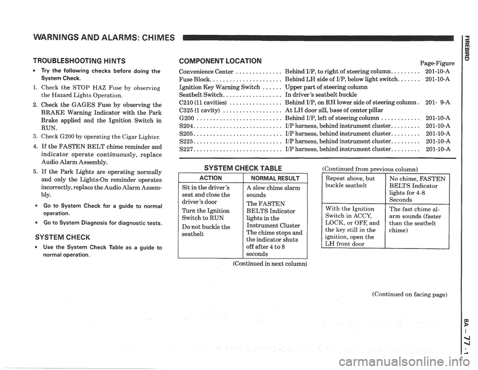
WARNINGS AND ALARMS: CHIMES
TROUBLESHOOTING H lNTS
* Try the following checks before doing the
System Check.
1. Check the STOP HAZ Fuse by observing
the Hazard Lights Operation.
2. Check the GAGES Fuse by observing the
BRAKE Warning Indicator with the Park
Brake applied and the Ignition Switch in
RUN.
3. Check 6200 by operating the Cigar Lighter.
4. If the FASTEN BELT chime reminder and
indicator operate continuously, replace
Audio Alarm Assembly.
5. If the Park Lights are operating normally
and only the Lights-On reminder operates
incorrectly, replace the Audio Alarm Assem-
bly.
Go to System Check for a guide to normal
operation.
Go to System Diagnosis for diagnostic tests.
SYSTEM CHECK
* Use the System Check Table as a guide to
normal operation.
COMPONENT LOCATlON Page-Figure
Convenience Center
.............. Behind IIP, to right of steering column. ........ 201-10-A
Fuse Block.
..................... Behind LH side of IIP, below light switch. ...... 201-10-A
Ignition Key Warning Switch
...... Upper part of steering column
Seatbelt Switch. ................. In driver's seatbelt buckle
C210
(11 cavities) ................ Behind IIP, on RH lower side of steering column. 201-
9-A
6325 (1 cavity) .................. At LH door sill, base of center pillar
6200 .......................... Behind IIP, left of steering column ............ 201-10-A
S204. .......................... IIP harness, behind instrument cluster. ........ 201-10-A
S205. .......................... IIP harness, behind instrument cluster. ........ 201-10-A
S225. .......................... I/P harness, behind instrument cluster. ........ 201-10-A
S227. .......................... IIP harness, behind instrument cluster. ........ 201-10-A
SYSTEM CHECK TABLE
ACTION
Sit in the driver's
seat and close the
driver's door
Turn the Ignition
Switch to RUN
Do not buckle the
seatbelt
NORMAL RESULT
A slow chime alarm
sounds
The FASTEN
BELTS Indicator
lights in the
Instrument Cluster
The chime stops and
the indicator shuts
off after 4 to
8
(Continued from previous column)
buckle
seatbelt
ignition, open the
LH front door
I seconds
(Continued in next column)
(Continued on facing page)
Page 1395 of 1825
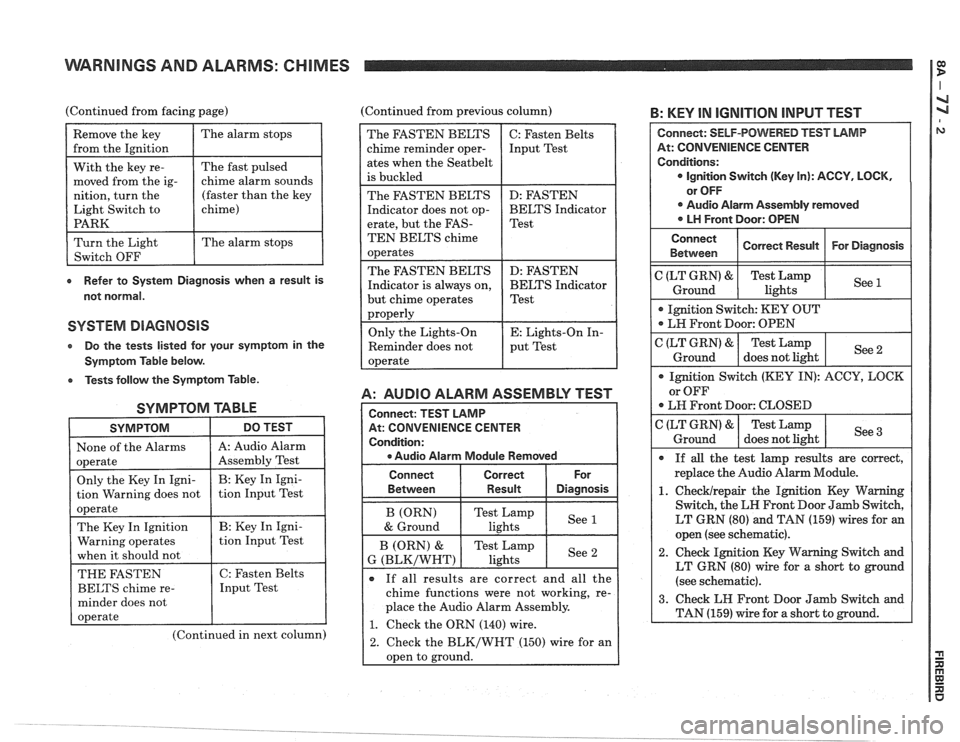
WARNINGS AND ALARMS: CHIMES I
(Continued from facing page) (Continued from previous column) B: KEY IN IGNITION INPUT TEST
e Refer to System Diagnosis when a result is
not normal.
SYSTEM DIAGNOSIS
Do the tests listed lor your symptom in the
Symptom Table below.
e Tests follow the Symptom Table.
SYMPTOM TABLE
SYMPTOM DO TEST I
1 None of the Alarms 1 A: Audio Alarm I
(Continued in next column)
A: AUDIO ALARM ASSEMBLY TEST
At: CONVENIENCE CENTER
e Audio Alarm Module Removed
The FASTEN BELTS
chime reminder oper-
ates when the
Seatbelt
is buckled
The FASTEN BELTS
Indicator does not op-
erate, but the
FAS-
TEN BELTS chime
operates
The FASTEN BELTS
Indicator is always on,
but chime operates
properly
Only the Lights-On
Reminder does not
operate
Connect Correct
Between
I Result Diasnosis
C: Fasten Belts
Input Test
D: FASTEN
BELTS Indicator
Test
D: FASTEN
BELTS Indicator
Test
E: Lights-On In-
put Test
If all results are correct and all the
chime functions were not working, re-
place the Audio Alarm Assembly.
1. Check the ORN (140) wire.
2. Check the BLK/WHT (150) wire for an
oDen to ground.
At: CONVENIENCE CENTER
LT GRN (80) and TAN (159) wires for an
open (see schematic).
2. Check Ignition Key Warning Switch and
LT GRN (80) wire for a short to ground
(see schematic).
Page 1396 of 1825
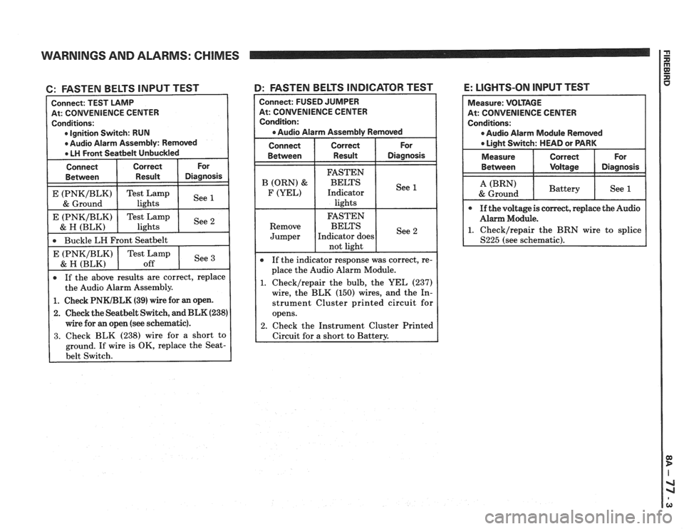
WARNINGS AND ALARMS: CHIMES
6: FASTEN BELTS INPUT TEST
At: CONVENIENCE CENTER
Ignition Switch: RUN
If the above results are correct, replace
the Audio Alarm Assembly.
Buckle
LH Front
Seatbelt
1. Check PNKIBLK (39) wire for an open.
2. Check the Seatbelt Switch, and BLK (238)
wire for an open (see schematic).
3. Check BLK (238) wire for a short to
ground. If wire is OK, replace the
Seat-
4: FASTEN BELTS INDICATOR TEST
See E (PNKIBLK)
& H (BLK)
Connect: FUSED JUMPER
At: CONVENIENCE CENTER
Condition:
a Audio Alarm Assembly Removed
Connect Correct For
Between Result Diagnosis
Test Lamp
off If
the indicator response was correct, re-
place the Audio Alarm Module.
1. Checklrepair the bulb, the YEL (237)
wire, the BLK (150) wires, and the In-
strument Cluster printed circuit for
opens.
2. Check the Instrument Cluster Printed
Circuit for
a short to Battery.
E: LIGHTS-ON INPUT TEST
At: CONVENIENCE CENTER
0 Audio Alarm Module Removed
Page 1397 of 1825
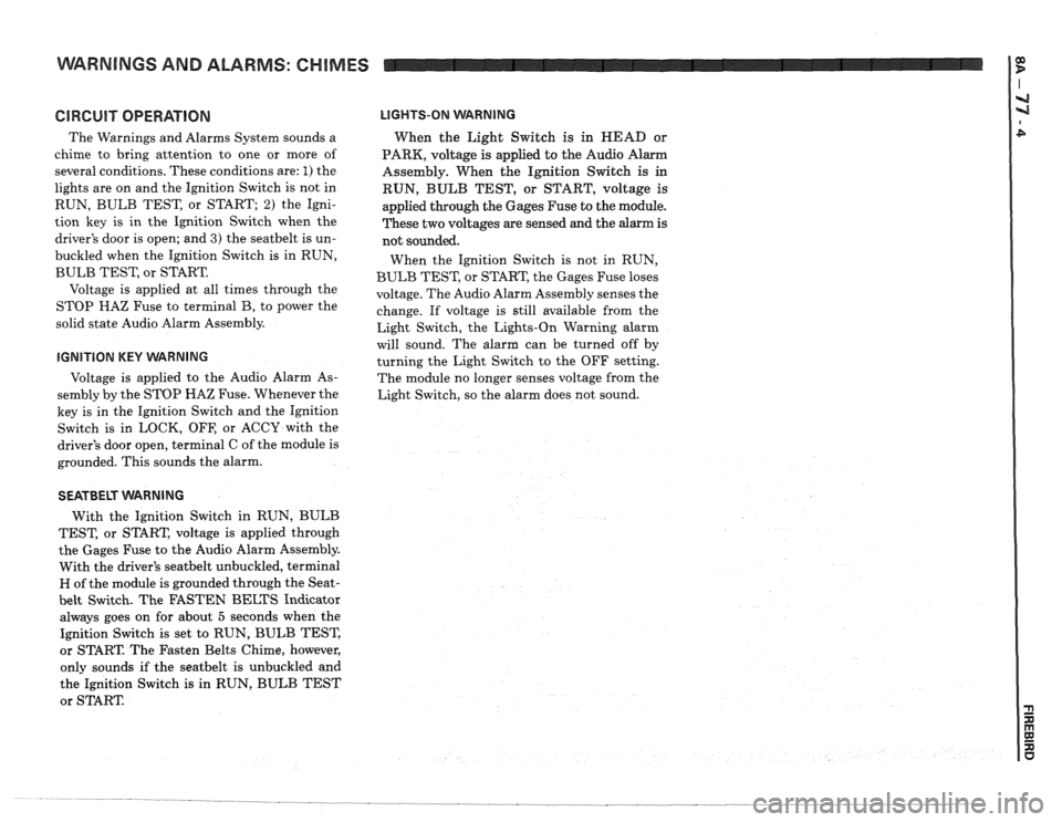
WARNINGS AND ALARMS: CHIMES
GlRGUlT OPERATION
The Warnings and Alarms System sounds a
chime to bring attention to one or more of
several conditions. These conditions are:
1) the
lights are on and the Ignition Switch is not in
RUN, BULB TEST, or START;
2) the Igni-
tion key is in the Ignition Switch when the
driver's door is open; and
3) the seatbelt is un-
buckled when the Ignition Switch is in RUN,
BULB TEST, or START.
Voltage is applied at all times through the
STOP
HAZ Fuse to terminal B, to power the
solid state Audio Alarm Assembly.
IGNITION KEY VVARNING
Voltage is applied to the Audio Alarm As-
sembly by the STOP HAZ Fuse. Whenever the
key is in the Ignition Switch and the Ignition
Switch is in LOCK, OFF, or ACCY with the
driver's door open, terminal C of the module is
grounded. This sounds the alarm.
LIGHTS-ON WARNING
When the Light Switch is in HEAD or
PARK, voltage
is applied to the Audio Alarm
Assembly. When the Ignition Switch
is in
RUN, BULB TEST, or START, voltage is
applied through the Gages Fuse to the module.
These two voltages are sensed and the alarm is
not sounded.
When the Ignition Switch is not in RUN,
BULB TEST, or START, the Gages Fuse loses
voltage. The Audio Alarm Assembly senses the
change. If voltage is still available from the
Light Switch, the Lights-On Warning alarm
will sound. The alarm can be turned off by
turning the Light Switch to the OFF setting.
The module no longer senses voltage from the
Light Switch, so the alarm does not sound.
SEATBELT WARNING
With the Ignition Switch in RUN, BULB
TEST, or START, voltage is applied through
the Gages Fuse to the Audio Alarm Assembly.
With the driver's
seatbelt unbuckled, terminal
H of the module is grounded through the Seat-
belt Switch. The FASTEN BELTS Indicator
always goes on for about
5 seconds when the
Ignition Switch is set to RUN, BULB TEST,
or START. The Fasten Belts Chime, however,
only sounds if the
seatbelt is unbuckled and
the Ignition Switch
is in RUN, BULB TEST
or START