1988 PONTIAC FIERO oil
[x] Cancel search: oilPage 938 of 1825
DRIVEABILITY AND EMISSIONS 5.OL (VIN F) & 5.7L (VIN 8) 6E3-C7-3
1. With a wire wheel, buff the exhaust deposits from
the mounting surface and around the valve.
2. Look for exhaust deposits in the valve outlet.
Remove deposit build-up with a screwdriver.
3. Clean mounting surfaces of intake manifold and
valve assembly.
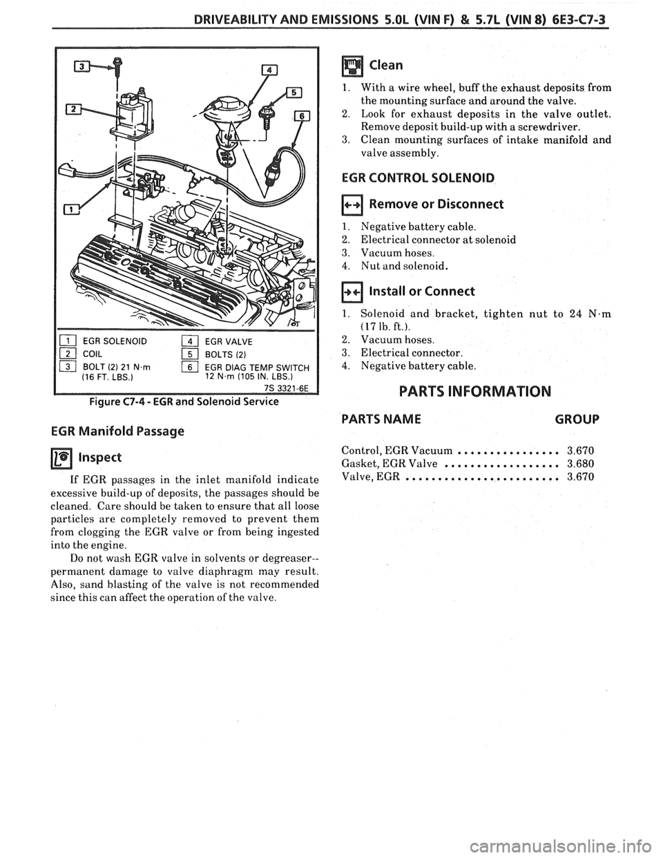
EGR SOLENOID 1 EGR VALVE
121 COIL 151 BOLTS (2)
ls] BOLT (2) 21 N.m EGR DlAG TEMP SWITCH
(16 FT. LBS.) 12 N.m (105
IN. LBS.)
Figure C7-4 - EGR and Solenoid Service
EGR Manifold Passage
Inspect
If EGR passages in the inlet manifold indicate
excessive build-up of deposits, the passages should be
cleaned. Care should be taken to ensure that all loose
particles are completely removed to prevent them
from clogging the EGR valve or from being ingested
into the engine.
Do not wash EGR valve in solvents or degreaser--
permanent damage to valve diaphragm may result.
Also, sand blasting of the valve is not recommended
since this can affect the operation of the valve.
EGR CONTROL SOLENOID
Remove or Disconnect
1. Negative battery cable.
2. Electrical connector at solenoid
3. Vacuum hoses.
4. Nut and solenoid.
Install or Connect
1. Solenoid and bracket, tighten nut to 24 N-m
(17 1b. ft.).
2. Vacuum hoses.
3. Electrical connector.
4. Negative battery cable.
PARTS INFORMATION
PARTS NAME GROUP
Control, EGR Vacuum ................ 3.670
Gasket, EGR Valve .................. 3.680
Valve, EGR ........................ 3.670
Page 943 of 1825
6E3-C8-2 5.OL (VIN F) & 5.7L (VIN 8) DRIVEABILITY AND EMISSIONS
15-WAY I.P. CONNECTOR
VEHICLE SPEED SIGNAL
SPEED INPUT
4TH GEAR SIGNAL
422
TANIBLK
4TH GEAR SW.
TRANSMISSION ALDL CONNECTOR
TCC APPLY SOLENOID
CHART C-8A
(Page 1 of 2)
AUTOMATIC TRANSMISSION CONVERTER CLUTCH (TCC)
5.OL (VIN F) & 5.7L (VIN 8) "F'" SERIES (PORT)
Circuit Description:
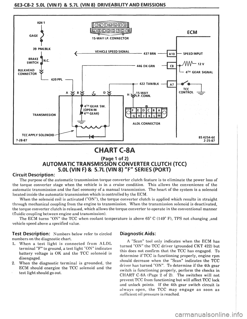
The purpose of the automatic transmission torque converter clutch feature is to eliminate the power loss of
the torque converter stage when the vehicle is in a cruise condition. This allows the convenience
of the
automatic transmission and the fuel economy of
a manual transmission. The heart of the system is a solenoid
located inside the automatic transmission which is controlled by the ECM.
When the solenoid coil is activated
("ON"), the torque converter clutch is applied which results in straight
through mechanical coupling from the engine to transmission. When the transmission solenoid is deactivated,
the torque converter clutch is released, which allows the torque converter to operate in the conventional manner
(fluidic coupling between engine
and transmission).
The ECM turns "ON" the TCC when coolant temperature is above
65" C (149" F), TPS not changing ,and
vehicle speed above
a specified value.
Test Description: Numbers below refer to circled Diagnostic Aids:
nbers on the diagnostic chart.
When
a test light is connected from ALDL
terminal "F" to ground, a test light "ON" indicates
battery voltage is
OK and the TCC solenoid is
disengaged.
When the diagnostic terminal is grounded, the
ECM should energize the TCC solenoid and the
test light should go out.
A "Scan" tool only indicates when the ECM has
turned "ON" the TCC driver (grounded CKT
422) but
this does not confirm that the TCC has engaged. To
determine if TCC is functioning properly, engine rpm
should decrease when the "Scan" indicates the TCC
driver has turned "ON". To determine if the 4th gear
switch is functioning properly, perform the checks in
CHAW C-8A (Page 2 of 2). The switches will not
prevent TCC
from functioning but will affect TCC lock
and unlock points. If the 4th gear switch circuit is
always open, the TCC may engage as soon as
si~t'ficient oil pressure is reached.
Page 945 of 1825
6E3-C8-4 5.OL (\/IN F) & 5.7b (VIN 8) DRIVEABILITY AND EMISSIONS
15-WAY I.P. CONNECTOR
SPEED INPUT
4TH GEAR SIGNAL
4TH GEAR SW.
TRANSMISSION
ALDL CONNECTOR
APPLY SOLENOID
CHART C-8A
(Page 2 of 2)
TRANSMISSION CONVERTER CLUTCH (TCC) ELECTRICAL DIAGNOSIS
5.OL (VIN F) & 5.7L (VIN 8) "F" XRlES (PORT)
Circuit Description:
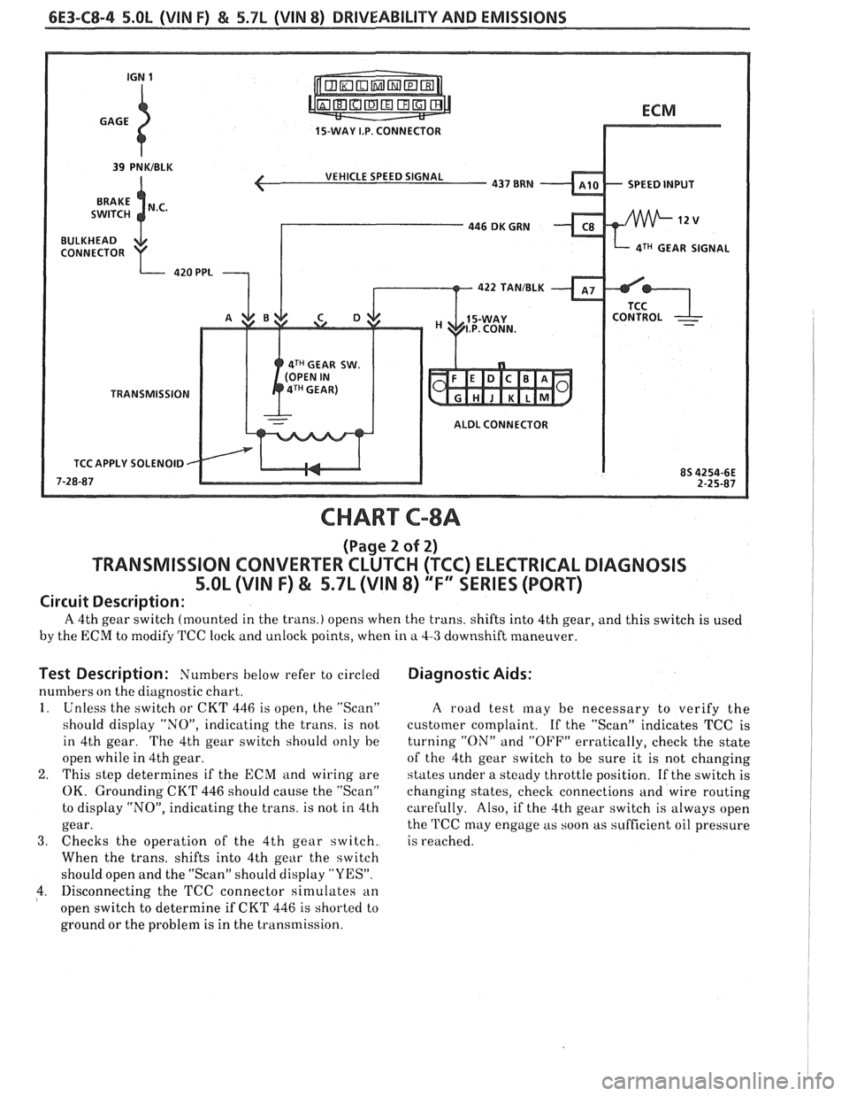
A 4th gear switch (mounted in the trans.) opens when the trans. shifts into 4th gear, and this switch is used
by the ECM to modify TCC lock and unlock points, when in a 4-3 downshift maneuver.
Test Description: Numbers below refer to circled
numbers on the diagnostic chart.
1. Unless the switch or CKT 446 is open, the "Scan"
should display "NOJ', indicating the trans. is not
in 4th gear. The 4th gear switch should only he
open while in 4th gear.
2. This step determines if the ECM and wiring are
OK. Grounding CKT 446 should cause the "Scan"
to display "NO", indicating the trans. is not in 4th
gear.
3. Checks the operation of the 4th gear switch.
When the trans, shifts into 4th gear the switch
should open and the "Scan" should display "YES".
4. Disconnecting the TCC connector sin~ulates an
open switch to determine if CKT 446 is shorted to
ground or the problem is in the transmission.
Diagnostic Aids:
A road test may be necessary to verify the
customer complaint.
If the "Scan" indicates TCC is
turning
"ON" and "OFF" erratically, check the state
of the 4th gear switch to be sure it is not changing
states under a steady throttle position. If the switch is
changing states, check connections and wire routing
carefully. Also, if the 4th gear switch is always open
the
'l'CC may engage as soon as sufficient oil pressure
is reached.
Page 951 of 1825
6E3-C12-2 5.OL (VIN F) & 5.7b (VIN 8) DRIVEABILITY AND EMISSIONS
FAN CONTROL
RELAY CONN.
DK GRNNVHT 335
TEMPERATURE
SENSOR SIGNAL.
TURNS ON PRIMARY
FAN AT
223OF (1 06'C)
CHART C-12
(Page 1 of 2)
COOLING FAN CONTROL CIRCUIT
5.8L (VIN F) & 5.7L (VIN 8) "F" SSERlES (PORT)
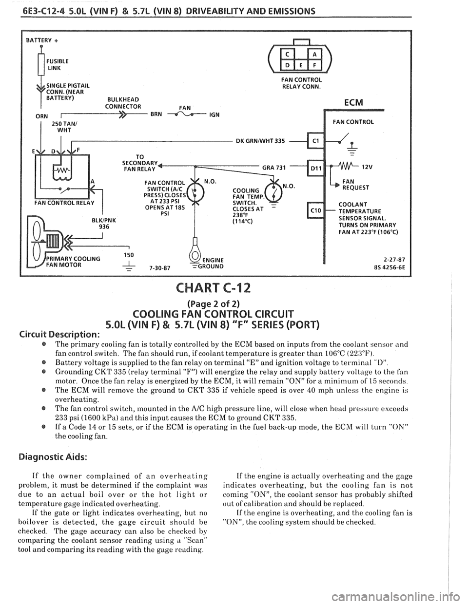
Circuit Description:
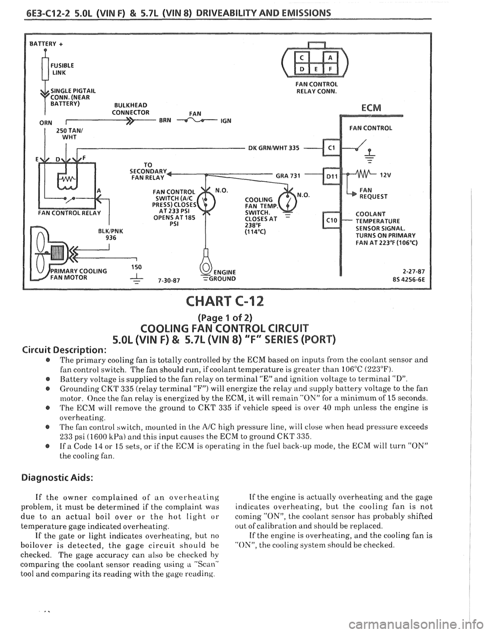
The primary cooling fan is totally controlled by the ECM based on inputs from the coolant sensor and
fan control switch. The fan should run, if coolant temperature is greater than 106°C
(223°F).
@ Battery voltage is supplied to the fan relay on terminal "En and ignition voltage to terminal "D".
@ Grounding CKT 335 (relay terminal "F") will energize the relay and supply battery voltage to the fan
motor. Once the fan relay is energized by the
ECM, it will remain "ON" for a minimum of 15 seconds.
@ 'I'he ECM will remove the ground to CKT 335 if vehicle speed is over 40 rnph unless the engine is
overheating.
@ 'I'he fan control switch, mounted in Lhe AIC high pressure line, will close when head pressure exceeds
233 psi (1600 kPa) and this input causes the ECM to ground CKT 335.
@ If a Code 14 or 15 sets, or if the ECM is operating in the fuel back-up mode, the ECM will turn "ON"
the cooling fan.
Diagnostic Aids:
If the owner complained of an overheating If
the engine is actually overheating and the gage
problem, it must be determined if the complaint was indicates
overheating, but
t,he cooling fan is not
due to an actual boil over or the hot light or coming
"ON", the
coolant sensor has probably shifted
temperature gage indicated overheating. out
of calibration and should be replaced.
If the gate or light indicates overheating, but no If
the engine is overheating, and the cooling fan is
boilover is detected, the gage circuit should be "ON", the cooling system should be checked.
checked. The gage accuracy can also be checked by
comparing the coolant sensor reading using
a "Scan.'
tool and comparing its reading with the gage reading.
Page 953 of 1825
6E3-C12-4 5.8L (VIN F) & 5.7L (VIN 8) DRIVEABILITY AND EMISSIONS
FAN CONTROL
SINGLE PIGTAIL RELAY CONN.
DK GRNNVHT 335
OPENS AT
185 TEMPERATURE SENSOR SIGNAL.
TURNS ON PRIMARY
FAN AT 223°F
(106°C)
CHART C-12
(Page 2 of 2)
COOLING FAN CONTROL CIRCUIT
5.OL (VIN F) & 5.7L (VIN 8) ""FYSERlES (PORT)
Circuit Description:
@ The primary cooling fan is totally controlled by the ECM based on inputs from the coolant sensor and
fan control switch. The fan should run, if coolant temperature is greater than 106°C
(223°F).
@ Battery voltage is supplied to the fan relay on terminal "En and ignition voltage to terminal "I)"
@ Grounding CKT 335 (relay terminal "F") will energize the relay and supply battery voltage to the fan
motor. Once the fan relay is energized by the ECM, it will remain "ON" for a mini~nuln of 15 seconds
@ The ECM will remove the ground to CKT 335 if vehicle speed is over 40 mph unless the engine is
overheating.
@ The fan control switch, mounted in the A/C high pressure line, will close when head pressure exceeds
233 psi (1600 kPa) and this input causes the ECM to ground CKT 335.
@ If a Code 14 or 15 sets, or if the ECM is operating in the fuel back-up mode, the ECM will turn "OX"
the cooling fan.
Diagnostic Aids:
If the owner complained of an overheating If the engine is actually overheating and the gage
problem, it must be determined if the complaint was indicates overheating, but the cooling fan is not
due to an actual boil over or the hot light or coming
"ON", the coolant sensor has probably shifted
temperature gage indicated overheating. out
of calibration and should be replaced.
If the gate or light indicates overheating, but no If the engine is overheating, and the cooling fan is
boilover is detected, the gage circuit should be "ON". the cooling system should be checked.
checked. The gage accuracy can also be checked
by
comparing the coolant sensor reading using a "Scan"
tool and comparing its reading with the gage reading.
Page 956 of 1825
DRIVEABILITY AND EMISSIONS 5.OL (VIN F) & 5.7L (VIN 8) 6E3-C13-1
SECTION C13
POSITIVE CRANKCASE VENTlLATlON (PCV)
CONTENTS
GENERAL DESCRIPTION ................ C13-1 FUNCTIONAL CHECK OF PCV VALVE .... C13-1
RESULTS OF INCORRECT OPERATION .... C13-1 ON-CARSERVICE ..................... C13-2
DIAGNOSIS
......................... C13-1 PARTS INFORMATION ................. C13-2
GENERAL DESCRIPTION
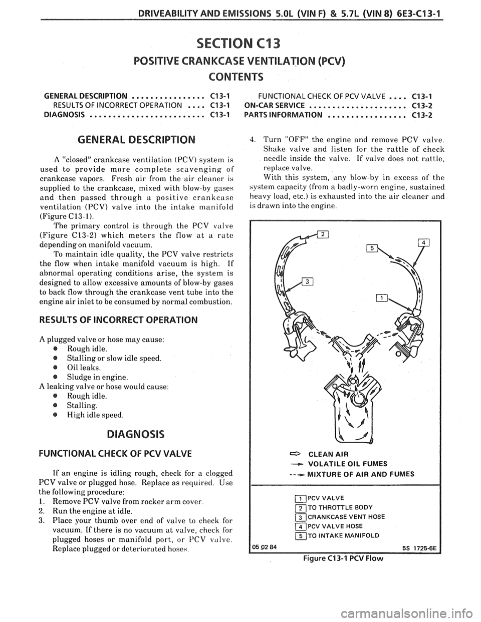
A "closed" crankcase ventilation (PCV) system is
used to provide more
cor~lplete scavenging of
crankcase vapors. Fresh air
from the air cleaner is
supplied to the crankcase, mixed with blow-by gases
and then passed through a positive crankcase
ventilation
(PCV) valve into the intake manifold
(Figure C13-I).
The primary control is through the PCV valve
(Figure
(213-2) which meters the flow at a rate
depending on manifold vacuum.
To maintain idle quality, the PCV valve restricts
the flow when intake manifold vacuum is high. If
abnormal operating conditions arise, the system is
designed to allow excessive amounts of blow-by gases
to back flow through the crankcase vent tube into the
engine air inlet to be consumed by normal combustion.
RESULTS OF INCORRECT OPERATION
A plugged valve or hose may cause:
@ Rough idle.
@ Stalling or slow idle speed.
@ Oil leaks.
@ Sludge in engine.
A leaking valve or hose would cause:
@ Rough idle.
@ Stalling.
@ High idle speed.
FUNCTIONAL CHECK OF PCV VALVE
If an engine is idling rough, check for a clogged
PCV valve or plugged hose. Replace as required. Use
the following procedure:
1. Remove PCV valve from rocker arm cover.
2. Run the engine at idle.
3. Place your thumb over end of valve lo check for
vacuum. If there is no vacuum at valve, check for
plugged hoses or manifold port, or
PCV valve.
Replace plugged or deteriorated hoses.
4. Turn "OFF" the engine and remove PCV valve.
Shake valve and listen for the rattle of check
needle inside the valve. If valve does not rattle,
replace valve.
With this system, any blow-by in excess of the
system capacity (from a badly-worn engine, sustained
heavy load,
etc.) is exhausted into the air cleaner and
is drawn into the engine.
a CLEAN AIR
VOLATILE OIL FUMES
--+- MIXTURE OF AIR AND FUMES
PCV VALVE
120 THROTTLE BODY
13 CRANKCASE VENT HOSE
1 PCV VALVE HOSE
I 150 INTAKE MANIFOLD I
Figure C13-1 PCV Flow
Page 957 of 1825
6E3-C13-2 5.OL (VIN F) & 5.7L (VIN 8) DRIVEABILITY AND EMISSIONS
Figure C13-3 Positive Crankcase Ventilation System (5.7L)
CHECK VALVE AS 00686E
Figure C13-2 PCV Valve Cross Section
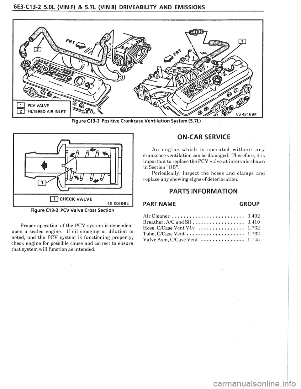
Proper operation of the PCV system is dependent
upon a sealed engine. If oil sludging or dilution is
noted, and the PCV system is functioning properly,
check engine for possible cause and correct to ensure
that system will function as intended.
ON-CAR SERVICE
An engine which is operated without any
crankcase ventilation can be damaged. Therefore, it is
important to replace the PCV valve at intervals shown
in Section
"OB".
Periodically, inspect the hoses and clamps and
replace any showing signs of deterio~ -a t' lon.
PARTS INFORMATION
PART NAME GROUP
Air Cleaner ......................... 3.402
.................. Breather, NC and Sil 3.410
................ Hose, CICase Vent Vlv 1.762
.................... Tube, CICase Vent 1.762
Valve Asm,
CICase Vent ............... 1.745
Page 959 of 1825
INDEX
SECTION PAGE
Cooling Fan Control
................. General Description C12-1
........................ Diagnosis C12-2
........................... Cuts Out B-5
................... Cylinder Select Error A-48
.................... Deceleration Mode C2-3
......................... Detonation B-4
..................... Dieseling. Run On B-6
............. Distributor Reference Signal C1-4
...................... ECM Terminals A-7
.................. ECM Wiring Diagram A3-A6
EGR Control Valve
................. General Description C7-1
................. Valve Identification C7-2
................... Diagnosis. Service C7-2
A-40
.................. EGR Control Solenoid C7-3
......................... EGR Check C7-4
Electronic Control Module
................. General Description C1-1
......................... Diagnosis C1-4
............................ Service C1-5
..................... Function Check C1-7
Electronic Spark Control (ESC) System
................. General Description C5-1
................... Diagnosis. Service C5-4
Electronic Spark Timing EST
............. A-50
A-52
Engine Cranks But Won't Run
............ A-14
........................ Engine Knock C5-4
.......................... ESC Module C5-2
.......................... ESC Sensor C5-1
.................... ESC System Check C5-4
................... ESTllgnition System C4-1
Evaporative Emission Control System
................. General Description C3-1
.......................... Diagnosis C3-2
Exhaust Emissions Excessive (Odors)
....... B-7
Exhaust Gas Recirculation (EGR) System
.... C7-1
Exhaust System Check Restricted
......... B-8
Fuel Control System
................. General Description C2- 1
......................... Diagnosis C2-5
..................... Fuel Cutoff Mode C2-3
SECTION PAGE
Fuel Injectors ........................
Fuel Pressure Connection Assy ............
Fuel Pressure Relief Procedure ...........
Fuel Pump Electrical Circuit .............
Fuel Pump Relay ......................
Fuel Rail
General Description
.................
........................... Service
Fuel System Diagnosis
..................
Fuel System Pressure Test ...............
Fuel Tank Pressure Control Valve .........
.......................... Hard Start B-2
.......... HE1 High Energy Ignition System C4-1
.......................... Hesitation
B-3
............ Idle Air Control System Check C2-20
.................. Idle Air
Control Valve C2-4
......................... Diagnosis C2-5
.................... Ignition System EST C4-1
........ Ignition System Check Integral Coil C4-4
........................ Incorrect Idle B-6
.................. Information Sensors C1.2. 9
.................. Injector
Balance Test C2-18
........................ lntermittents B-2
........................ Knock Sensor C1-3
........................ Lack Of Power B-4
......... Light. Manual Transmission Shift C8-6
.............. Light. Service Engine Soon A-10
MAF Sensor
.................. General Description C1-2
.......................... Diagnosis C1-5
A.42.44. 46
............................ Service C1-8
... Manual Transmission Electrical Diagnosis C8-10
MAT Sensor
.................. General Description C1-2
......................... Diagnosis C1-5
A.34. 38