Page 995 of 1825
700-R4-6 HYDRAULIC DIAGNOSIS
L PRESSURE CHECK NFORMAT
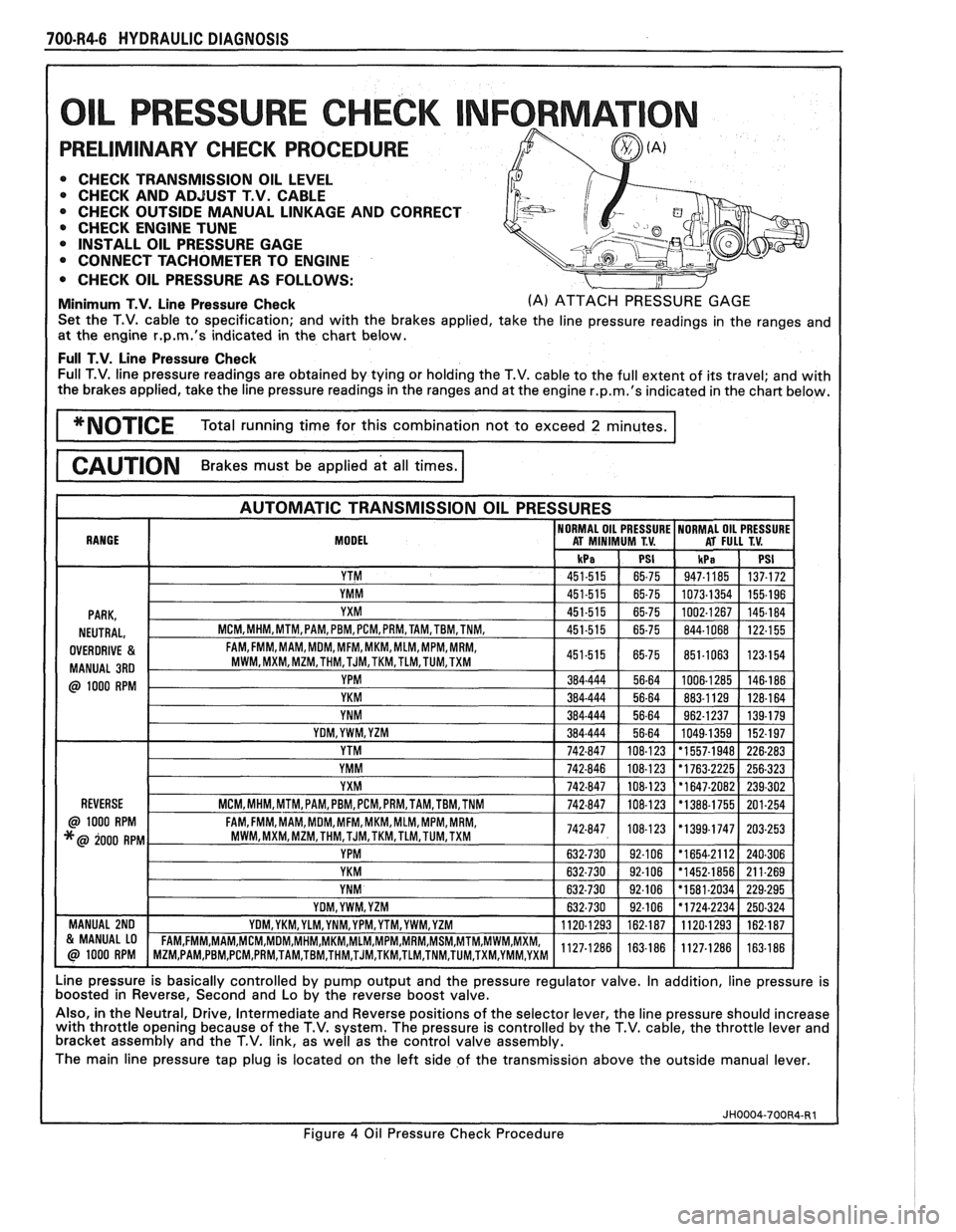
PRELIMINARY CHECK PROCEDURE
0 CHECK TRANSMISSION OIL LEVEL 0 CHECK AND ADJUST T.V. CABLE
0 CHECK OUTSIDE MANUAL LINKAGE AND CORRECT
@ CHECK ENGINE TUNE
0 INSTALL OIL PRESSURE GAGE
CONNECT TACHOMETER TO ENGINE
0 CHECK OIL PRESSURE AS FOLLOWS:
Minimum T.V. Line Pressure Check (A) ATTACH PRESSURE GAGE
Set the T.V. cable to specification; and with the brakes applied, take the line pressure readings in the ranges and
at the engine
r.p.m.'s indicated in the chart below.
Full T.V. Line Pressure Check Full T.V. line pressure readings are obtained by tying or holding the T.V. cable to the full extent of its travel; and with
the brakes applied, take the line pressure readings in the ranges and at the engine
r.p.m.'s indicated in the chart below.
MODEL
Line pressure is basically controlled by pump output and the pressure regulator valve. In addition, line pressure is
boosted in Reverse, Second and Lo by the reverse boost valve.
Also, in the Neutral, Drive, Intermediate and Reverse positions of the selector lever, the line pressure should increase
with throttle opening because of the T.V. system. The pressure is controlled by the T.V. cable, the throttle lever and
bracket assembly and the T.V. link, as well as the control valve assembly.
The main line pressure tap plug is located on the left side of the transmission above the outside manual lever.
Figure
4 Oil Pressure Check Procedure
Page 997 of 1825
700-R4-8 HYDRAULIC DIAGNOSIS
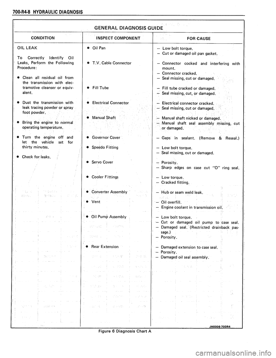
OIL LEAK - Low bolt torque.
- Cut or damaged oil pan gasket.
To Correctly Identify Oil
Leaks, Perform the Following
T.V. Cable Connector - Connector cocked and interfering with
Procedure:
- Connector cracked.
0 Clean all residual oil from - Seal missing, cut or damaged.
the transmission with
elec-
tramotive cleanser or equiv- - Fill tube cracked or damaged.
alent.
- Seal missing, cut, or damaged.
0 Dust the transmission with 0 Electrical Connector - Electrical connector cracked.
leak tracing powder or spray
- Seal missing, cut or damaged.
foot powder.
@ Manual Shaft - Manual shaft nicked or damaged.
Bring the engine to normal
- Manual shaft seal assembly missing, cut
operating temperature.
Turn the engine off and Governor Cover
- Gaps in sealant. (Remove & Reseal.)
let the vehicle set for
Speedo Fitting
- Low bolt torque.
- Seal missing, cut or damaged.
Check for leaks.
@ Servo Cover
Cooler Fittings
- Cracked fitting.
0 Converter Assembly - Hub or seam weld leak.
- Oil overfill.
- Engine coolant in transmissio
0 Oil Pump Assembly
Rear Extension
- Damaged extension to case seal.
Figure
6 Diagnosis Chart A
Page 998 of 1825
HYDRAULIC DIAGNOSIS 700-R4-9
A OILPAN G OIL PUMP SEAL ASSEMBLY L MANUAL SHAFT SEAL
B CASE
H OIL PUMP TO CASE SEAL M GOVERNOR COVER
C COOLER CONNECTORS
& 1 CONVERTER
N SPEEDOSEAL
PLUGS J VENT 0 EXTENSION TO CASE SEAL
D T.V. CABLE SEAL
K ELECTRICAL CONNECTOR P EXTENSION OIL SEAL
E SERVO COVER SEAL ASSEMBLY
F OIL FILL TUBE SEAL
Figure
7 Possible Leak Points
Page 999 of 1825
100.R4.10 HYDRAULIC DIAGNOSIS
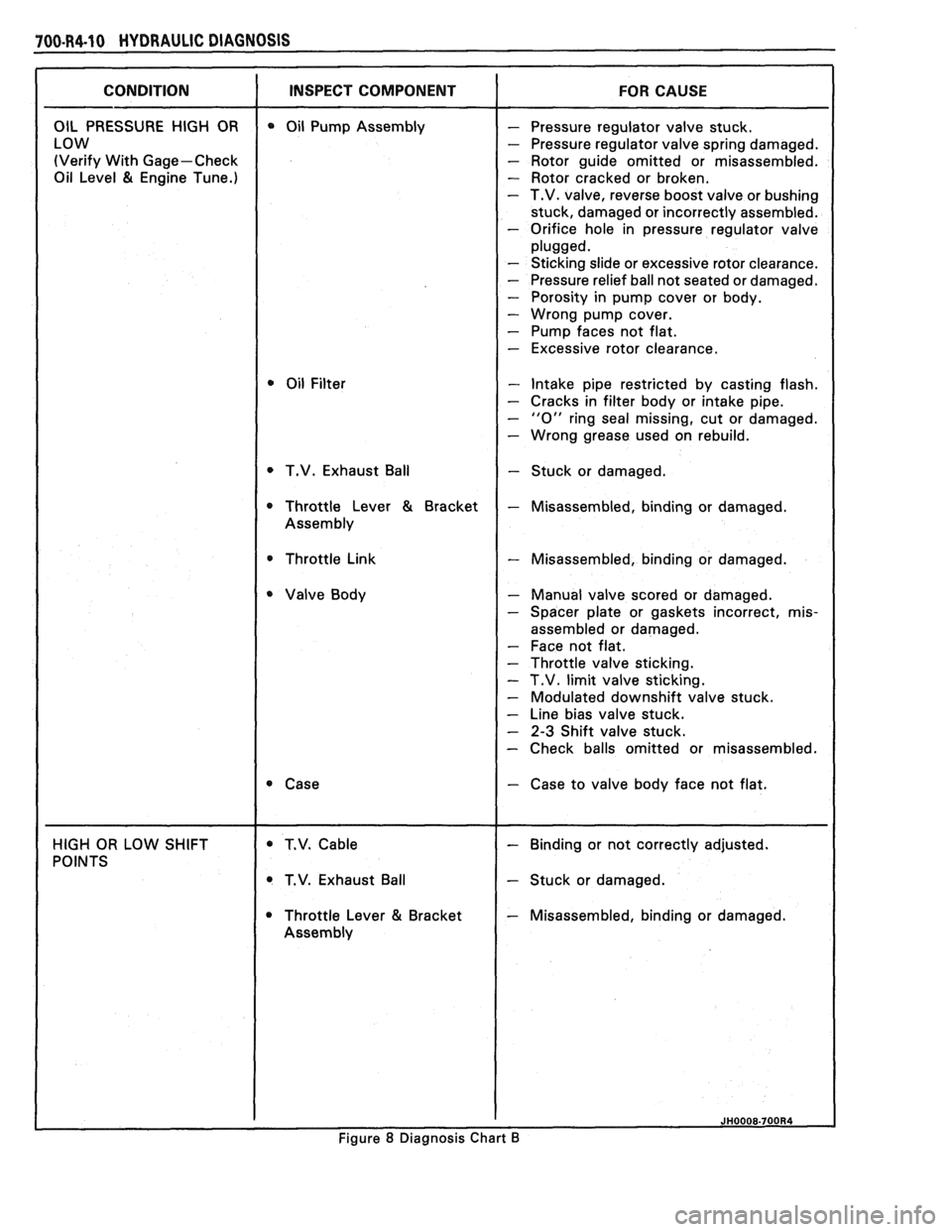
(Verify With Gage-Check - Rotor guide omitted or misassembled.
Oil Level
81 Engine Tune.) - Rotor cracked or broken. - T.V. valve, reverse boost valve or bushing
stuck, damaged or incorrectly assembled.
- Orifice hole in pressure regulator valve
- Sticking slide or excessive rotor clearance.
- Pressure relief ball not seated or damaged.
- Porosity in pump cover or body.
- Wrong pump cover.
- Pump faces not flat.
- Excessive rotor clearance.
- Intake pipe restricted by casting flash.
- Cracks in filter body or intake pipe.
- "0" ring seal missing, cut or damaged.
- Wrong grease used on rebuild.
T.V. Exhaust Ball
- Stuck or damaged.
* Throttle Link - Misassembled, binding or damaged.
- Manual valve scored or damaged.
- Spacer plate or gaskets incorrect, mis-
assembled or damaged.
- Face not flat.
- Throttle valve sticking.
- T.V. limit valve sticking.
- Modulated downshift valve stuck.
- Line bias valve stuck.
- 2-3 Shift valve stuck.
- Check balls omitted or misassembled.
- Case to valve body face not flat.
T.V. Exhaust Ball
- Stuck or damaged.
Throttle Lever
81 Bracket - Misassembled, binding or damaged.
Figure
8 Diagnosis Chart B
Page 1000 of 1825
HYDRAULIC DIAGNOSIS 700-R4-I 1
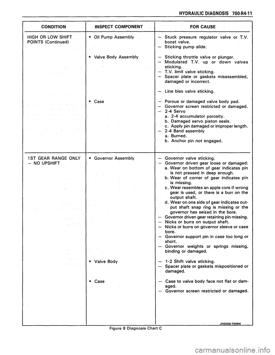
CONDITION I INSPECT COMPONENT
HIGH OR LOW SHIFT
POINTS (Continued) 0 Oil Pump Assembly
0 Valve Body Assembly
Case
Valve Body
- Stuck pressure regulator valve or T.V.
boost valve.
- Sticking pump slide.
- Sticking throttle valve or plunger.
- Modulated T.V. up or down valves
sticking.
- T.V. limit valve sticking. - Spacer plate or gaskets misassembled,
damaged or incorrect.
I - Line bias valve sticking.
- Porous or damaged valve body pad.
- Governor screen restricted or damaged.
- 2-4 Servo
a. 2-4 accumulator porosity.
b. Damaged servo piston seals.
c. Apply pin damaged or improper length.
- 2-4 Band assembly
a. Burned.
b. Anchor pin not engaged.
- Governor valve sticking. - Governor driven gear loose or damaged:
a. Wear on bottom of gear indicates pin
is not pressed in deep enough.
b. Wear of corner of gear indicates pin
is missing.
c. Wear resembles an apple core if wrong
gear is used, or there is a burr on the
output shaft.
d. Wear on one side of gear indicates out-
put shaft snap ring is missing or the
governor has seized in the bore.
- Governor driven gear retaining pin missing.
- Nicks or burrs on output shaft.
- Nicks or burrs on governor sleeve or case
bore.
- Governor support pin in case too long or
short.
- Governor weights or springs missing,
binding or damaged.
- 1-2 Shift valve sticking. - Spacer plate or gaskets mispositioned or
damaged.
- Case to valve body face not flat or dam-
aged.
- Governor screen restricted or damaged.
Figure 9 Diagnosis Chart C
Page 1002 of 1825
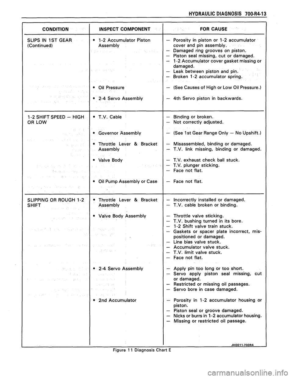
HYDRAULIC DIAGNOSIS 700434-13
CONDITION I INSPECT COMPONENT I FOR CAUSE
SLIPS IN 1 ST GEAR 1-2 Accumulator Piston
(Continued) Assembly
I
0 Oil
Pressure
- Porosity in piston or 1-2 accumulator
cover and pin assembly.
- Damaged ring grooves on piston.
- Piston seal missing, cut or damaged.
- 1-2 Accumulator cover gasket missing or
damaged.
- Leak between piston and pin.
- Broken 1-2 accumulator spring.
- (See Causes of High or Low Oil Pressure.)
- 4th Servo piston in backwards.
1-2 SHIFT SPEED
- HIGH
OR LOW T.V.
Cable
I Governor Assembly
Throttle Lever
& Bracket
Assembly
Valve Body
I
0 Oil Pump Assembly or Case
- Binding or broken.
- Not correctly adjusted.
- (See 1 st Gear Range Only - No Upshift.)
- Misassembled, binding or damaged. - T.V. link missing, binding or damaged.
- T.V. exhaust check ball stuck.
- T.V. plunger sticking.
- Face not flat.
- Face not flat.
SLIPPING OR ROUGH 1-2
SHIFT Throttle
Lever
& Bracket
Assembly
Valve Body Assembly
* 2-4 Servo Assembly
2nd Accumulator
- Incorrectly installed or damaged. - T.V. cable broken or binding.
Throttle valve sticking.
T.V. bushing turned in its bore.
1-2 Shift valve train stuck.
Gaskets or spacer plate incorrect,
mis-
positioned or damaged.
Line bias valve stuck.
Accumulator valve stuck.
T.V. limit valve stuck.
Face not flat.
, - Apply pin too long or too short.
1 - Servo apply piston seal missing, cut
or damaged.
I - Restricted or missing oil passages.
1 - Servo bore in case damaged.
/ - Porosity in 1-2 accumulator housing or
piston.
- Piston seal or groove damaged.
- Nicks or burrs in 1-2 accumulator housing.
- Missing or restricted oil passage.
I I JH0011-700R4
Figure 11 Diagnosis Chart E
Page 1004 of 1825
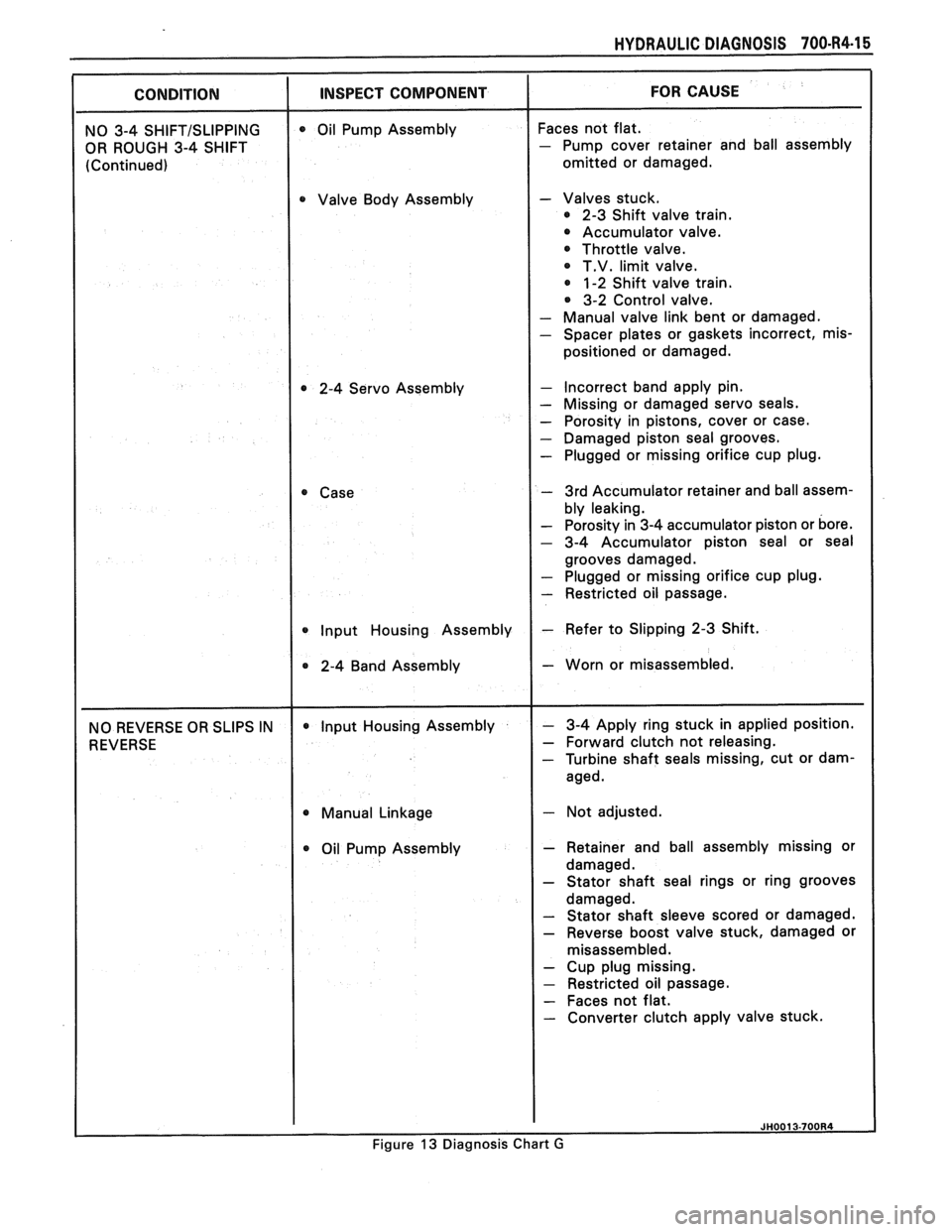
HYDRAULIC DIAGNOSIS 700434-15
OR ROUGH 3-4 SHIFT
omitted or damaged.
Valve Body Assembly
- Valves stuck.
2-3 Shift valve train.
Accumulator valve.
Throttle valve.
@ T.V. limit valve.
1-2 Shift valve train.
3-2 Control valve.
- Manual valve link bent or damaged.
- Spacer plates or gaskets incorrect, mis-
positioned or damaged.
2-4 Servo Assembly
- Incorrect band apply pin. - Missing or damaged servo seals.
- Porosity in pistons, cover or case.
- Damaged piston seal grooves. - Plugged or missing orifice cup plug.
- 3rd Accumulator retainer and ball assem-
- Porosity in 3-4 accumulator piston or bore.
- 3-4 Accumulator piston seal or seal
grooves damaged.
- Plugged or missing orifice cup plug.
- Restricted oil passage.
2-4 Band Assembly
- Worn or misassembled.
- Forward clutch not releasing. - Turbine shaft seals missing, cut or dam-
@ Manual Linkage - Not adjusted.
Oil Pump Assembly
- Retainer and ball assembly missing or
- Stator shaft seal rings or ring grooves
- Stator shaft sleeve scored or damaged.
- Reverse boost valve stuck, damaged or
misassem bled.
- Cup plug missing.
- Restricted oil passage.
- Faces not flat. - Converter clutch apply valve stuck.
Figure 13 Diagnosis Chart G
Page 1006 of 1825
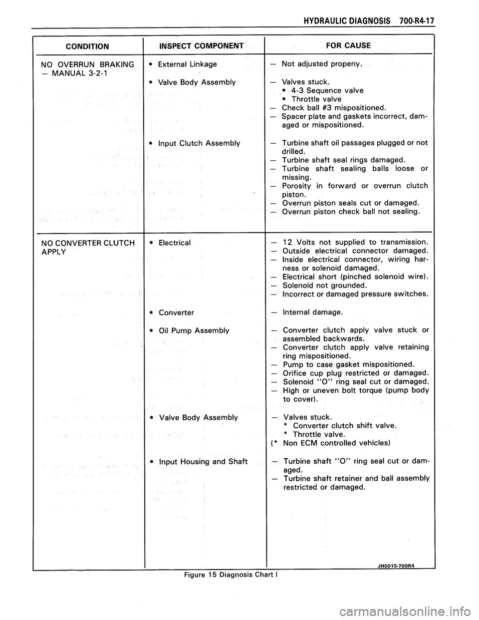
HYDRAULIC DIAGNOSIS 700-R4-17
0 Valve Body Assembly - Valves stuck.
4-3 Sequence valve
Throttle valve
- Check ball #3 mispositioned. - Spacer plate and gaskets incorrect, dam-
aged or mispositioned.
Input Clutch Assembly
- Turbine shaft oil passages plugged or not
- Turbine shaft seal rings damaged.
- Turbine shaft sealing balls loose or
- Porosity in forward or overrun clutch
- Electrical short (pinched solenoid wire).
- Solenoid not grounded. - Incorrect or damaged pressure switches.
- Internal damage.
Oil Pump Assembly
- Converter clutch apply valve stuck or
assembled backwards.
- Converter clutch apply valve retaining
ring mispositioned.
- Pump to case gasket mispositioned.
- Orifice cup plug restricted or damaged.
- Solenoid "0" ring seal cut or damaged.
- High or uneven bolt torque (pump body
Valve Body Assembly
- Valves stuck.
* Converter clutch shift valve.
* Throttle valve.
(* Non ECM controlled vehicles)
Input Housing and Shaft
- Turbine shaft "0" ring seal cut or dam-
restricted or damaged.
Figure
15 Diagnosis Chart I