Page 1007 of 1825
-*Converter clutch shift valve stuck.
(* Non ECM controlled vehicles)
0 Oil Pump Assembly - Converter clutch apply valve stuck.
- Restricted oil passage.
- Crack in filter body.
- Flash restricting filter neck. - "0" ring seal cut or damaged.
0 Miscellaneous - Low oil pressure.
- Engine not tuned properly.
0 Input Housing and Shaft - Turbine shaft "0" ring cut or damaged. - Turbine shaft retainer and ball assembly
restricted or damaged.
- lnternal damage.
Oil Pump Assembly
- Converter clutch apply valve stuck.
0 Manual Linkage - Incorrectly adjusted.
- Disconnected.
- Face not flat.
- lnternal leakage.
pport pin too long or missing.
0 Forward Sprag Clutch Sprag assembly installed backwards.
- Parking bracket damaged or not torqued
Figure
16 Diagnosis Chart J
Page 1008 of 1825
NO PARK (Continued]
RATCHETING NOISE
OIL OUT THE VENT
VIBRATION IN REVERSE
AND WHINING NOISE IN
PARK
HYDRAULIC DIAGNOSIS 700.R4-1
INSPECT COMPOMEMT FOR CAUSE
Parking Unkage (Cont.) - Inside detent lever not torqued properly.
- Detent roller mispositioned or not torqued
properly. - Parking pawl binding or damaged.
Parking Pawl - Parking pawl return spring weak, dam-
aged or m isassern bled.
Oil Pump
Valve Body
Miscellaneous
I
- Chamfar in pump body rotor pocket too
large.
I - T.V. limit valve stuck.
- Fluid level - overfilled.
Oil Pump
Page 1010 of 1825

HYDRAULIC DIAGNOSIS 700.R4-21
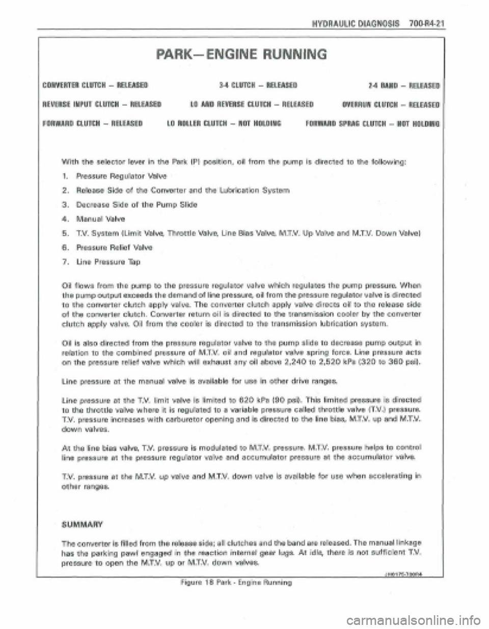
PARK- ENGlNE RUNNING
CONVERTER CLUTCH - RELEASED 34 CLUTCH - RELEASED 2.4 MUD - RELEASE0
REVERSE INPUT CLUTCH - RELEASED LO AND REVERIE CLUTCH - RELEASED OVERRUN CLUTCH - RELEASE0
FORWARD WUTCH - RELEASED LO ROUM CLUfCH - NOT HOLOlWO FORWARD SPRAQ CLUTCH - NaT HOLDIIYG
With the selector lever in the Park (PI position, oil from the pump is directed to the following:
1. Pressure Regulator Valve
2. Releasg Side of the Converter and the Lubrication System
3, Decrease Side of the Pump Slide
4. Manual Valve
5. T.V. System (Limit Valve, Throttle Valve, Line Bias Valve, M.T.V. Up Valve and M.T.V. Down Valve)
6. Pressure Relief Valve
7. Line Pressure Tap
Oil
flows from the pump to the pressure regulator vatve which regulates the pump pressure. When
the pump output exceeds the demand of line pressure, oil from the pressure regulator valve is directed
to the converter clutch apply valve. The converter clutch apply valve directs oil to the release side
of the converter clutch. Converter return oil is directed to the transmission cooler by the converter
clutch
apply valve, Oil from the cooler is directed to the transmission lubrication system.
Oil is also directed from the pressure regulator valve to the pump slide to decrease pump output in
relation to the combined pressure of M.T.V. oil and regulator valve spring force. Line pressure acts
on the pressure relief valve which will exhaust any oil above 2,240 to 2,520 kPa (320 to 360 psi).
Line pressure at the manual valve is available for use in other drive ranges.
Line pressure at the T.V. limit valv~ is limited to 620 kPa (90 psi). This limited pressure is directed
to the throttle valve where it is regulated to a variable pressure called throttle valve (T.V,) pressurn
T.V. pressure increases with carburetor opening and is directed to the line bias, MXV. up and M.T.V.
down valves.
At the line bias valve, T.V. pressure is modulated to M.T.V. pressure. M.T.V. pressure helps to control
line pressure
at the pressure regulator valve and accumulator pressure at the sceumulator valve.
T.V, pressure at the M.T.V. up valve and M.T,V. down valve js available for use when accelerating in
other ranges.
SUMMARY
The convener is filled from the release side; all clutches and the band are released. The manual linkage
has the parking pawl engaged in the reaction internal gehr lugs. At idle, them is not sufficient T,V.
pressure to open the MXV, up or M.T.V. down vakes.
JHO176.7OOR4 1
Figure 18 Park - Engine Running
Page 1012 of 1825
HYDRAULIC DIAGNOSIS 700.R4-23
NEUTRAL-- ENGINE RUNNING
34 CLU~H - RELEASED 2.4 MlD - RELEASED COlVERTER CLUTCH - RELEASED
REVERSE IMPU CLUTCH - RELEASED LO MD REVERSE CLUTCH - RELEASED OVERRUN CLUTCH - RELEASED
FORWARD CLUTCH - RELEASED LO ROLLER CLUfCH - MOT HOLDING FORWARD tPRAG CLUTCH - Hm HOLDlWG
When the selector lever Is moved to the Neutral IN1 position, the line pressure is directed to the same
areas as in Park, except in Neutral (N) the manual valve directs oil into the Reverse, Neutral, Drive
4, Drive 3 (RN04031 oil is directed to the 2-3 shift valve which directs RND403 oil to the 3-4 relay
valve through the servo feed passaga Oil at these valves is available for use in other ranges.
SUMMARY
The converter is filled from the release side; all clutches and the band are released, At idle, there is
not sufficient T,V. pressure to open the M.T,V. up or M.T.V. down valves.
I JHO176-fQOR4 Figure 20 Neutral - Engine Running
Page 1014 of 1825

HYDRAULIC DIAGNOSIS 70064-2
FORWARD CLUTCH - APPLIED
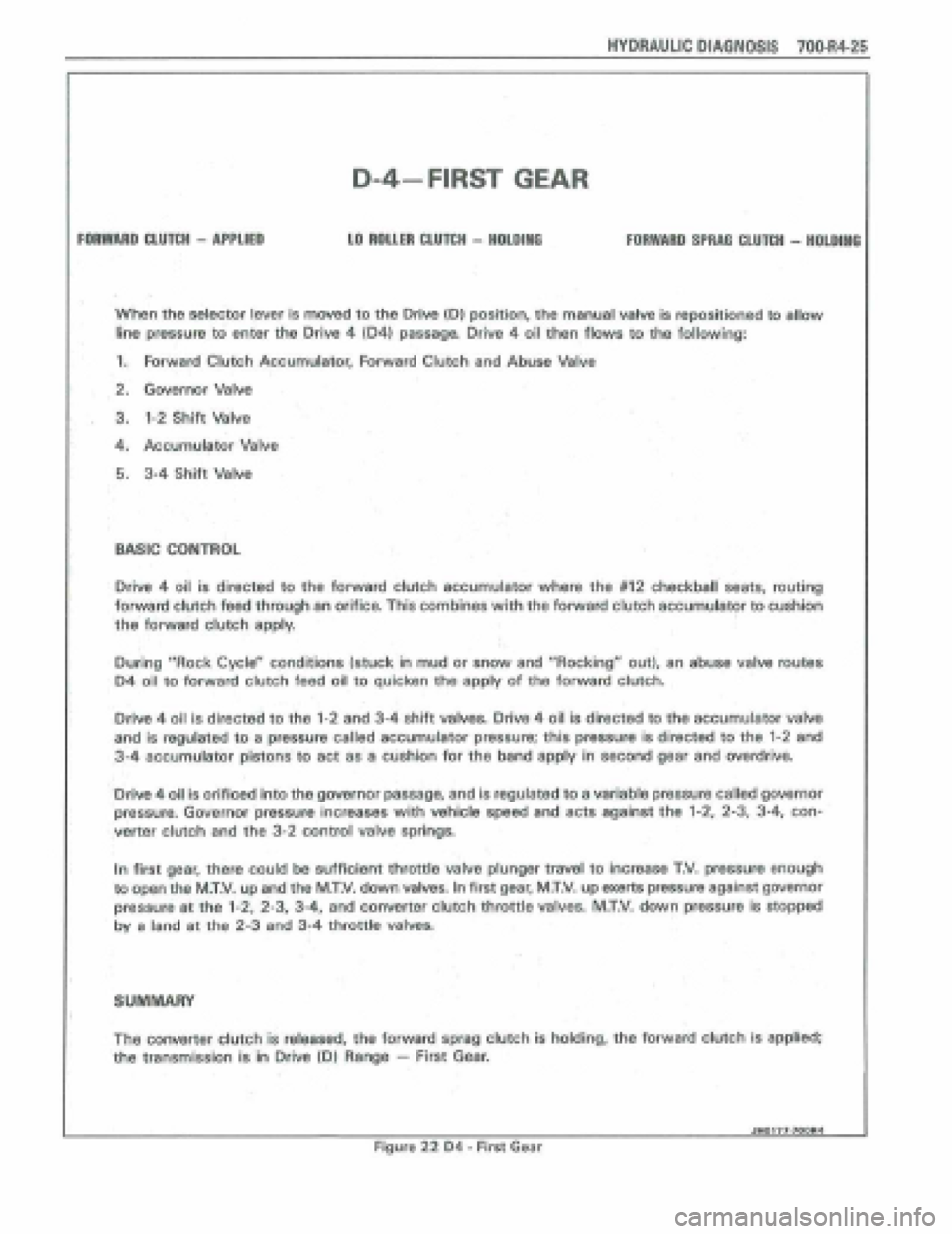
D-4-FIRST GEAR
LO ROLLER CLUTCH - HOLDlllO FORWARO SPRRQ CLUTCH - HOLDING
When the selector lever is moved to the Orive {Dl position, the manual valve is repositioned to allow
line pressure to enter the Drive 4 104) passaga Drive 4 oil then flows to the following:
1. Forward Clutch Accumulator, Forward Clutch and Abuse Valve
2. Governor Valve
. 3. 1-2 Shift Valve
4, Accumulator Valve
5. 3-4 Shift Valve
BASIC CONTROL
Drive 4 oil is directed to the forward clutch accumulator where the #I2 checkball seats, routing
forward clutch feed through an orifice. This combines with the forward clutch accumuIator to cushion
the forward clutch
apply,
During "Rock Cyclea' cpnditions (stuck in mud or snow and "Rocking" out), an abuse valve routes
D4 oil to forward clutch feed oil to quicken the apply of the forward clutch.
Driw 4 oil is directed to the 1-2 and 3-4 shift valves, Drive 4 oil is directed to the accumulator valve
and is regulated to a pressure called accumulator pressure; this pressure is directed to the 1-2 and
3-4 accumulator pistons to act as a cushion for the band apply in second gear and overdrive.
'Drive
4 oil is orificed into the gwernor passage, and is regulated to a variable pressure called governor
pressure. Governor pressure increases with vehicle speed and acts against the 1-2, 2-3, 3-4, con-
verter clutch and the 3-2 control valve springs.
In first gear, there could
be sufficient throttle valve plunger travel to increase T.V. pressure enough
to open the MW. up and the M.T.V. down valves. In first gear, MXV. up exerts pressure against governor
pressure at the 1-2, 2-3, 3-4, and converter clutch throttle valves. M.T.V. down pressure is stopped
by a land at the 2-3 and 34 throttle valves,
SUMMARY
The converter clutch is released, the forward sprag dutch is holding, the forward clutch is applied;
the transmission is i'n Drive (Dl Range - First Gear.
I Jn0177-700M Figure 22 D4 - First Gsar
Page 1016 of 1825

HYDRAULIC PlAONOSlS fOO-R4-27
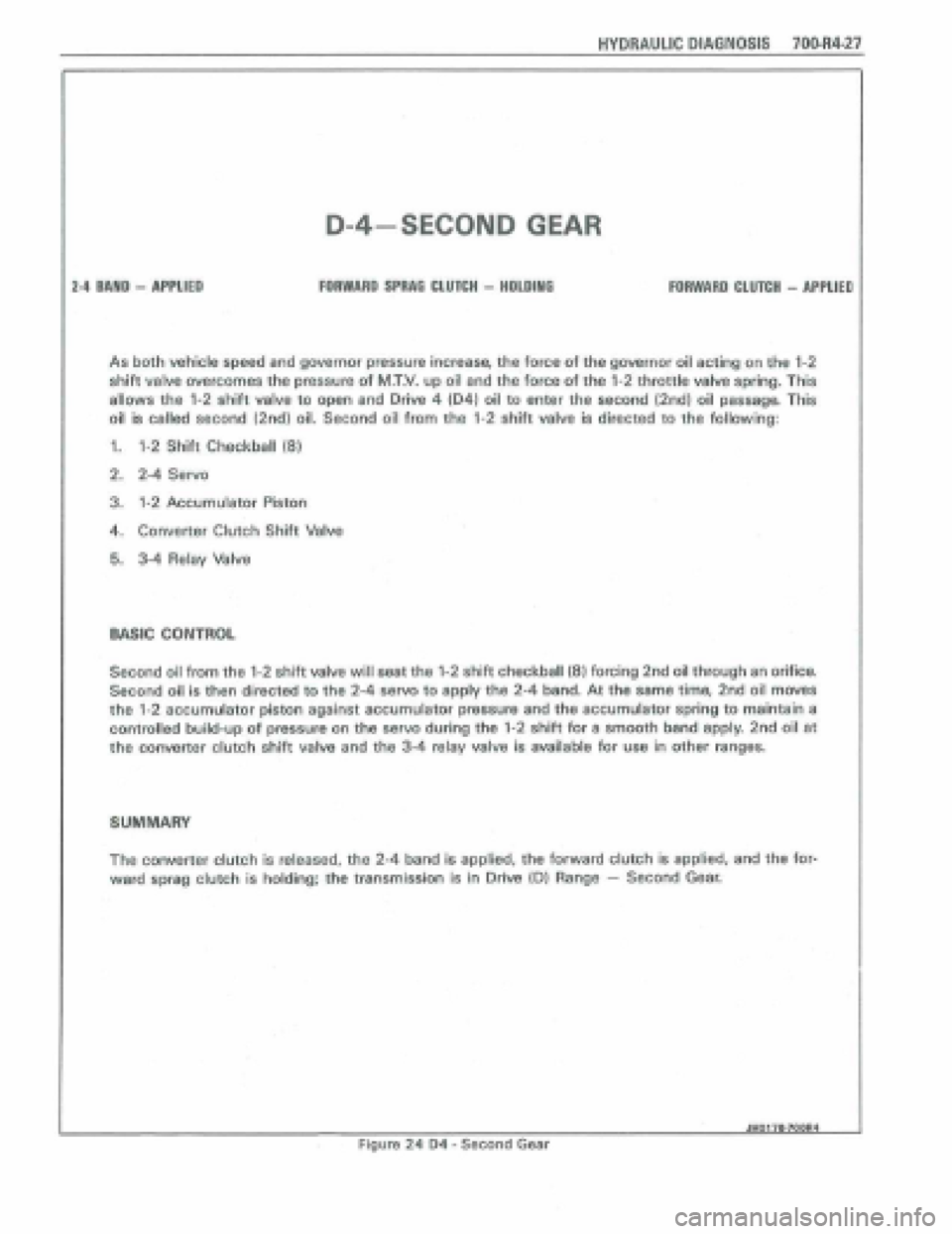
D-4-SECOND GEAR
FORWARD SPRAE CLUTCH - HOLDlMO 24 BAND - APPLIED FOIWARD CLUTCH - APPLIEP
As both vehicle speed and govanor pressure increase, the force of the governor oil acting on the 1-2
shift valve overcomes the pressure of M.T.V. up oil and the force of the 1-2 throttle valve spring. This
allows the 1-2 shift valve to open and Drive 4 (041 oil to enter the second (2nd) oil passage. This
oil is called second (2nd) oil. Second oil from the 1-2 shift valve is directed to the following:
1. 1-2 Shift Checkbatl (8)
2, 2-4 Servo
3. 1-2 Accumulator Piston
4. Converter Clutch Shift Valve
5. 3-4 Relay Valve
WlC CONTROL
Second ail from the 1-2 shift valve will seat the 1-2 shift checkball (8) forcing 2nd oil through an orifice.
Second oil Is then directed to the 2-4 servo to apply the 2-4 band. At the same time, 2nd oil moves
the 1-2 eccumulator piston against accumulator pressure and the accumulator spring to maintain a
controlled build-up of pressure on the servo during tho 1-2 shift for a smooth bend apply 2nd oil at
the converter clutch shift vatve and the 3-4 relay valve is availabl~ for use in other ranges.
SUMMARY
The converter clutch is released, the 2-4 band is applied, the forward clutch is applied, and the for-
ward spmg clutch is holding; the transmission is in Drive (Dl Range - Second Gear,
dH017B.7OOR4 -
Figure 24 D4 - Second Gear
Page 1017 of 1825
70bR4-28 HYDRAULIC DIAGNOSIS
D-4 SECOND GEAR
(CONVERTER SIGNAL OIL)
Page 1018 of 1825
HYDRAULIC DIAGNOSIS 700.R4.29
CO#YEA'TER CLUTCH - APPUEO
FDRWMO CLUTCtl - APPUED
D-4-SECOND GEAR
I Converter Signal 011 1
2-4 BAMD - APPLIED
FORWARD SWAG CLUTCH - HOLDiNQ
NON EC.M. CONTROLLED VEHICLES
As vehicle speed and governor pressure increase, the force of the governor oil acting on the converter
clutch shift valve overcomes the pressure of M.T.V. up oil and the force of the converter clutch T.V.
spring. This allows the converter clutch shift valve to open and 2nd oil to enter the converter clutch
signal
passaga Converter signal oil will exhaust at the T.C.C. sotenoid until a signal is received from
the vehicles external controls.
E.C.M. CONTROLLED VEHICLES
Second oil 'is rerouted into converter clutch signal oil at the bore plugs used in place of the converter
clutch shift valve. Conwrter signal oil exhausts at this solenoid until a signal is received from the vehicles
EC.M.
JHOl7klW14
Figure 26 I14 - Second Gear - Converter Signal Oil