1988 PONTIAC FIERO drain bolt
[x] Cancel search: drain boltPage 376 of 1825
2.8 LITER V-6 6A2-25
Fitting
1. Select rings comparable in size to the piston being
used.
2. Slip
the compression ring in the cylinder bore;
then press the ring down into the cylinder bore
about 6mm above ring travel. Be sure ring is
square with cylinder wall.
3. Measure the space or gap between the ends of the
ring with a feeler gage (Figure
6A2-33).
4. If
the gap between the ends of the ring is below
specifications, remove the ring and try another
for fit.
5. Fit each compression ring to the cylinder in
which it is going to be used.
6. If the pistons have not been cleaned and inspected
as previously outlined, do so.
7. Slip the outer surface of the top and second
compression ring into the respective piston ring
groove and roll the ring entirely around the
groove (Figure
6A2-34). If binding occurs at any
point, the cause should be determined. If there is
a ring groove, remove by dressing with a fine cut
file. If the binding is caused by a distorted ring,
check a new ring.
Installation
1. Install oil ring spacer in groove being sure ends
are butted and not overlapped.
2. Hold
spacer ends butted and install lower steel oil
ring rail.
3. Install upper
steel oil ring rail with gap staggered.
4. Flex
the oil ring assembly to make sure ring is
free. If binding occurs, the cause should be
detemined. If caused by ring groove, remove by
dressing groove with a fine cut file. If binding is
caused by a distorted ring, check a new ring.
5. Install second compression ring. Stagger gap
from other rings.
6. Install top compression ring with gap properly
located.
ENGINE ASSEMBLY
Removal
Disconnect battery.
Remove air cleaner.
Remove hood. Drain radiator.
Remove lower radiator hose.
Remove upper fan shroud.
Remove upper radiator hose and coolant
recovery hose.
Remove transmission cooler lines. Remove radiator.
Remove fan assembly.
Remove heater hoses.
Disconnect carburetor linkage, includes cruise
control detent cable.
Remove vacuum brake booster line.
Remove distributor cap and lay wiring aside.
Disconnect necessary wires and hoses.
Remove power steering pump and lay aside. Raise
vehicle.
Remove exhaust pipes at exhaust manifold.
Remove dust cover.
Remove converter bolts.
Disconnect starter wires.
Remove bell housing bolts.
Remove motor mount through bolts.
Disconnect fuel lines at fuel pump.
Lower vehicle. Support transmission.
Remove
A.I.R./Converter pipes bracket.
Remove engine, include removing wire from
bracket at rear left of engine.
Installation
Position engine assembly in vehicle.
Attach motor mount to engine brackets and
lower engine in place.
Remove engine lifting device.
Remove transmission floor jack.
Raise vehicle on hoist.
Install mount "through" bolts. Torque to
specifications.
Install bell housing bolts. Torque to
specifications.
On vehicles with automatic transmission, install
converter to flywheel attaching bolts. Torque to
specifications.
Install flywheel splash shield of conveter housing
cover as applicable. Torque attaching bolts to
specifications.
Install starter wires.
Connect fuel lines.
Connect exhaust pipe at manifold.
Lower vehicle on hoist.
Reinstall power steering pump, if so equipped.
Connect necessary wires and hoses.
Install radiator and fan shroud and reconnect
radiator and heater hoses.
Fill cooling system.
Fill crankcase with oil. See owner's manual for
specifications.
Install air cleaner.
Install hood.
Connect battery cables.
NOTICE: To avoid possible arcing of battery,
connect positive battery cable first.
22. Start engine, check for leaks and check timing.
CRANKSHAFT
The crankshaft can be removed while the engine
is dissasembled for overhaul, as previously outlined or
without complete disassembly.
Removal
1. With the engine removed from the vehicle,
remove the clutch assembly (if equipped) and
flywheel. Mount engine in stand and clamp
securely.
Page 385 of 1825
6A3-6 V-8 ENGINE
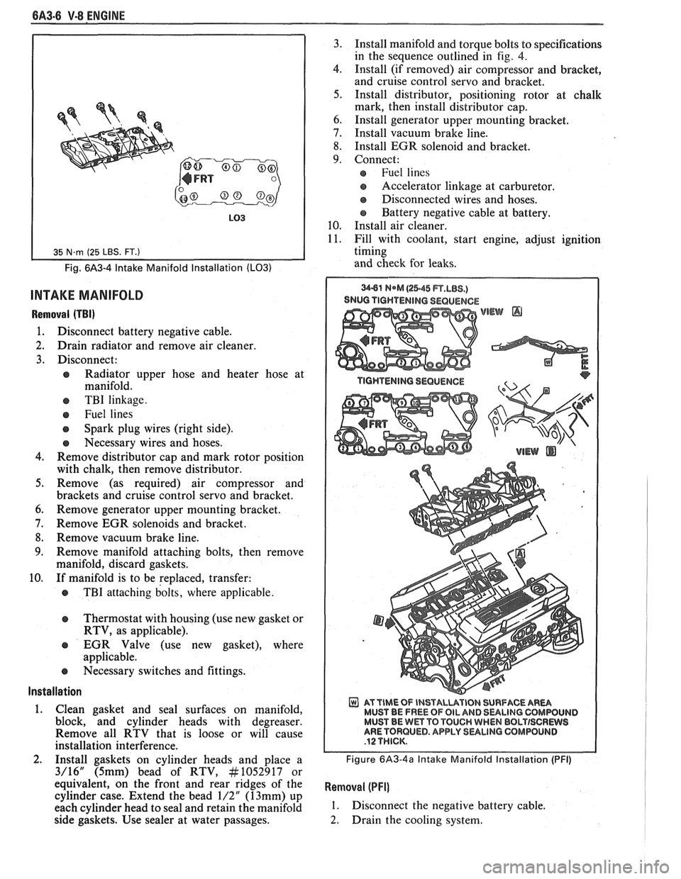
Fig. 6A3-4 Intake Manifold Installation (LO31
INTAKE MANIFOLD
Removal (TBI)
1. Disconnect battery negative cable.
2. Drain radiator and remove air cleaner.
3. Disconnect:
e Radiator upper hose and heater hose at
manifold.
e TBI linkage.
e Fuel lines
Spark plug wires (right side).
e Necessary wires and hoses.
4. Remove distributor cap and mark rotor position
with chalk, then remove distributor.
5. Remove (as required) air compressor and
brackets and cruise control servo and bracket.
6. Remove generator upper mounting bracket.
7. Remove EGR solenoids and bracket.
8. Remove vacuum brake line.
9. Remove manifold attaching bolts, then remove
manifold, discard gaskets.
10. If manifold is to be replaced, transfer:
e TBI attaching bolts, where applicable.
Thermostat with housing (use new gasket or
RTV, as applicable).
EGR Valve (use new gasket), where
applicable.
e Necessary switches and fittings.
lnstallation
1. Clean gasket and seal surfaces on manifold,
block, and cylinder heads with degreaser.
Remove all RTV that is loose or will cause
installation interference.
2. Install gaskets on cylinder heads and place a
3/16" (5mm) bead of RTV, At1052917 or
equivalent, on the front and rear ridges of the
cylinder case. Extend the bead
1/2" (13mm) up
each cylinder head to seal and retain the manifold
side gaskets. Use sealer at water passages. 3.
Install manifold and torque bolts to specifications
in the sequence outlined in
fig. 4.
4. Install (if removed) air compressor and bracket,
and cruise control servo and bracket.
5. Install distributor, positioning rotor at chalk
mark, then install distributor cap.
6. Install generator upper mounting bracket.
7. Install vacuum brake line.
8. Install EGR solenoid and bracket.
9. Connect:
Fuel lines
s Accelerator linkage at carburetor.
@ Disconnected wires and hoses.
Battery negative cable at battery.
10. Install air cleaner.
11. Fill with coolant, start engine, adjust ignition
timing
and check for leaks.
SNUG TIGHTENING SEQUENCE
WEW @
AT TIME OF INSTALUVIBN SURFACE AR- MUST BE FREE OF OIL AND 8ULlNG CQMWUIJD MUST BE Wm TO TOUCH WHEN BBLTISCRWS ARE TORQUED. APPLY SULINO GOMPOLINB
Figure 6A3-4a Intake Manifold Installation (PFI)
Removal (PFI]
1. Disconnect the negative battery cable.
2. Drain the cooling system.
Page 391 of 1825
6A3-12 V-8 ENGINE
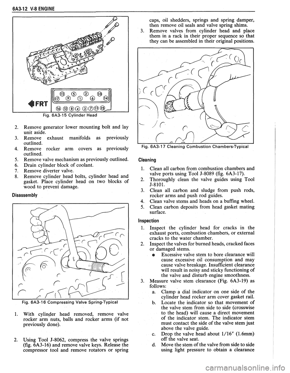
Fig. 6A3-15 Cylinder Head
2. Remove generator lower mounting bolt and lay
unit aside.
3. Remove exhaust manifolds as previously
outlined.
4. Remove rocker arm covers as previously
outlined.
5. Remove valve mechanism as previously outlined.
6. Drain cylinder block of coolant.
7. Remove diverter valve.
8. Remove cylinder head bolts, cylinder head and
gasket. Place cylinder head on two blocks of
wood to prevent damage.
Disassembly
1. With cylinder head removed, remove valve
rocker arm nuts, balls and rocker arms (if not
previously done).
2. Using Tool
5-8062, compress the valve springs
(fig.
6A3-16) and remove valve keys. Release the
compressor tool and remove rotators or spring caps, oil shedders,
springs and spring damper,
then remove oil seals and valve spring shims.
3. Remove valves from cylinder head and place
them in a rack in their proper sequence so that
they can be assembled in their original positions.
Cleaning I
1. Clean all carbon from combustion chambers and
valve ports using Tool J-8089 (fig.
6A3-17).
2. Thoroughly clean the valve guides using Tool
5-8101.
3. Clean
all carbon and sludge from push rods,
rocker arms and push rod guides.
4. Clean valve stems and heads on a buffing wheel.
5. Clean carbon deposits from head gasket mating
surface.
Inspection I
1. Inspect
the cylinder head for cracks in the
exhaust ports, combustion chambers, or external
cracks to the water chamber.
2. Inspect the valves for burned heads, cracked faces
or damaged stems.
e Excessive valve stem to bore clearance will
cause excessive oil consumption and may
cause valve breakage. Insufficient clearance
will result in noisy and sticky functioning of
the valve and disturb engine smoothness.
3. Measure valve stem clearance (Fig. 6A3-19) as
follows:
a. Clamp a dial indicator
on one side of the
cylinder head rocker arm cover gasket rail.
b. Locate
the indicator so that movement of
the valve stem from side to side (crosswise
to the head) will cause a direct movement
of the indicator stem. The indicator stem
must contact the side of the valve stem just
above the valve guide.
c. Drop
the valve head about 1/16"
(1.6mm)
off the valve seat.
d. Move the stem of the valve from side to side
using light pressure to obtain a clearance
Page 397 of 1825
6A3-18 V-8 ENGINE
bore, remove remover and installer tool and
bearing from puller screw.
5. Remove remaining bearings (except front and
rear) in the same manner. It will be necessary to
index pilot in camshaft rear bearing to remove the
rear intermediate bearing.
6. Assemble remover
and installer tool on driver
handle and remove camshaft front and rear
bearings by driving towards center of cylinder
block.
lnstallation
The camshaft front and rear bearings should be
installed first. These bearings will act as guides for the
pilot and center the remaining bearings being pulled
into place.
1. Assemble remover
and installer tool on driver
handle and install camshaft front and rear
bearings by driving towards center of cylinder
block.
2. Using Tool Set J-6098, with nut then thrust
washer installed to end of threads, index pilot in
camshaft front bearing and install puller screw
through pilot.
3. Index camshaft bearing in bore (with oil hole
aligned as outlined below), then install remover
and installer tool on puller screw with shoulder
toward bearing.
e Number one cam bearing oil hole must be
positioned so that oil holes are equidistant
from 6 o'clock position.
e Number two through number four bearing
oil holes must be positioned at 5 o'clock
position (toward left side of engine and at a
position even with bottom of cylinder bore).
e Number five bearing oil hole must be in 12
o'clock position.
4. Using two wrenches, hold puller screw while
turning nut. After bearing has been pulled into
bore, remove the remover and installer tool from
puller screw and check alignment of oil hole in
camshaft bearing.
5. Install remaining bearings in the same manner. It
will be necessary to index pilot in the camshaft
rear bearing to install the rear intermediate
bearing.
6. Coat new camshaft rear plug O.D. with
# 1052080 sealant, or equivalent, and install
flush to 1/32"
(.80mm) deep.
OIL PAN
Removal
1. Disconnect battery negative cable.
2. Remove fan shroud.
3. Remove air cleaner and lay aside if equipped.
4. Remove distributor cap and lay aside.
5. Raise vehicle.
6. Drain crankcase.
7. Disconnect exhaust pipe at manifold.
8. Disconnect AIR pipe clamp.
9. Disconnect converter hanger bolts and allow
exhaust to hang down.
GASKET
ENGINE OIL PRESSURE 10 LBS.
1 REINFORCEMENT
MINIMUM AT 500 RPM AND 30-55
1 OIL PAN
LBS. AT 2000 RPM.
161 RETAINER
OIL FILTER BY-PASS VALVE STUD
(LB9, L98)
OPERATES
AT 9- TO 11 LBS. STUD (L98)
PRESSURE.
OIL PUMP
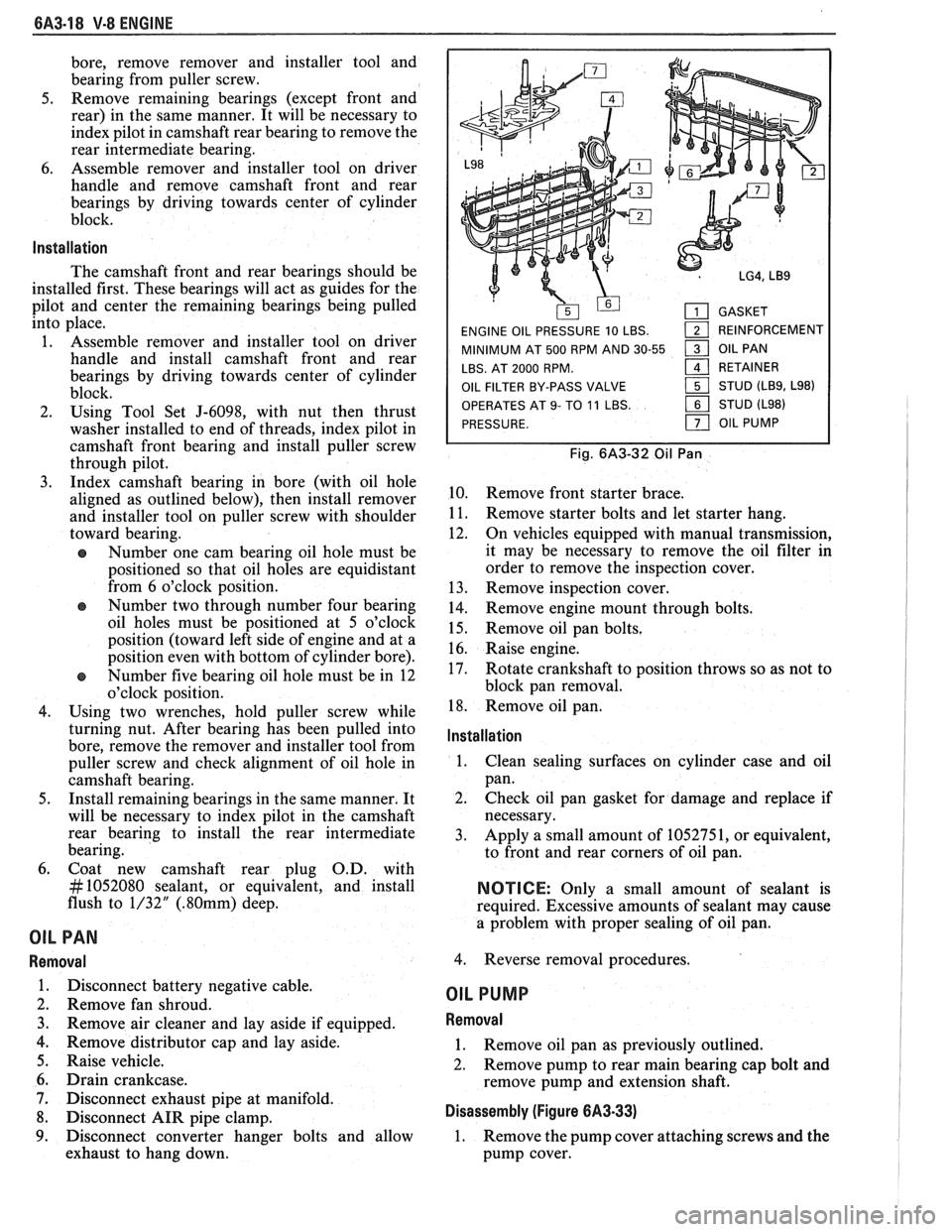
Fig. 6A3-32 Oil Pan
10. Remove front starter brace.
11. Remove starter bolts and let starter hang.
12. On vehicles equipped with manual transmission,
it may be necessary to remove the oil filter in
order to remove the inspection cover.
13. Remove inspection cover.
14. Remove engine mount through bolts.
15. Remove oil pan bolts.
16. Raise engine.
17. Rotate crankshaft to position throws so as not to
block pan removal.
18. Remove oil pan.
lnstallation
1.
Clean sealing surfaces on cylinder case and oil
pan.
2. Check oil pan gasket for damage and replace if
necessary.
3. Apply a small amount of 1052751, or equivalent,
to front and rear corners of oil pan.
NOTICE: Only a small amount of sealant is
required. Excessive amounts of sealant may cause
a problem with proper sealing of oil pan.
4. Reverse removal procedures.
OIL PUMP
Removal
1. Remove oil pan as previously outlined.
2. Remove pump to rear main bearing cap bolt and
remove pump and extension shaft.
Disassembly (Figure 6A3-33)
1. Remove the pump cover attaching screws and the
pump cover.
Page 406 of 1825
V-8 ENGINE 6A3-27
3. When finish honing
a cylinder bore to fit a piston,
the hone should be moved up and down at a
sufficient speed to obtain very fine uniform
surface finish marks in a cross-hatch pattern of
approximately
45" to 65" included angle. The
finish marks should be clean but not sharp, free
from imbedded particles and torn or folded
metal.
4. Permanently mark
the piston for the cylinder to
which it has been fitted and proceed to hone
cylinders and fit the remaining pistons.
NOTICE: Handle the pistons with care and do not
attempt to force them through the cylinder until
the cylinder has been honed to correct size as this
type piston can be distorted through careless
handling.
5. Thoroughly
clean the bores with hot water and
detergent. Scrub well with a stiff bristle brush and
rinse thoroughly with hot water. It is extremely
essential that a good cleaning operation be
performed. If any of the abrasive material is
allowed to remain in the cylinder bores, it will
rapidly wear the new rings and cylinder bores in
addition to the bearings lubricated by the
contaminated oil, the bores should be swabbed
and then wiped with a clean dry cloth. Cylinder
should not be cleaned with kerosene or gasoline.
Clean the remainder of the cylinder block to
remove the excess material spread during the
honing operation.
Piston Selection
1. Check USED piston to cylinder bore clearance as
follows:
a. Measure
the "Cylinder Bore Diameter"
with a telescope gage
"2-1/2" (64mm) from
top of cylinder bore").
b. Measure
the
"Piston Diameter" (at skirt
across center line of piston pin).
c. Subtract
piston diameter from cylinder bore
diameter to determine "Piston to Bore
Clearance".
d. Determine if piston to bore clearance is in
the acceptable range.
2. If
used piston is not acceptable, check Piston Size
Chart and determine if a new piston can be
selected to fit cylinder bore within the acceptable
range.
3. If
cylinder bore must be reconditioned, measure
new piston diameter (across center line of piston
pin) then hone cylinder bore to correct clearance
(preferable range).
4. Mark the piston to identify the cylinder for which
it was fitted.
OIL FILTER BYPASS VALVE
Inspection and Replacement
With the oil filter removed, check the spring and
fibre valve for operation. Inspect for a cracked or
broken valve. If replacement is necessary, the oil filter
adapter and bypass valve assembly must be replaced as an
assembly. Clean valve chamber in cylinder block
thoroughly. Torque retaining screws to specifications.
ENGINE ASSEMBLY
Removal
1. Disconnect battery.
2. Remove air cleaner.
3. Remove hood.
4. Drain radiator.
5. Remove lower radiator hose.
6. Remove upper fan shroud.
7. Remove upper radiator hose and coolant
recovery hose.
8. Remove transmission cooler lines.
9. Remove radiator.
10. Remove fan assembly.
1 1. Remove heater hoses.
12. Disconnect
carburetor linkage, includes cruise
control detent cable.
13. Remove vacuum brake booster line.
14. Remove
distributor cap and lay wiring aside.
15. Disconnect necessary wires and hoses.
16. Remove power steering
pump and lay aside.
17. Raise vehicle.
18. Remove exhaust
pipes at exhaust manifold.
19. Remove dust cover.
20. Remove converter bolts.
2 1. Disconnect starter wires.
22. Remove bell housing bolts.
23. Remove
motor mount through bolts.
24. Disconnect fuel lines
at fuel pump.
25. Lower vehicle.
26. Support transmission.
27. Remove
A.I.R./Converter pipe bracket.
28. Remove engine, include removing wire
from
bracket at rear left of engine.
Installation
1. Position engine
assembly in vehicle.
2. Attach
motor mount to engine brackets and
lower engine in place.
3. Remove engine lifting device.
4. Remove transmission floor jack.
5. Raise vehicle on hoist.
6. Install mount "through" bolts. Torque to
specifications.
7. Install bell housing bolts. Torque to
specifications.
8. On vehicles with automatic transmissions, install
I
converter to flywheel attaching bolts. Torque to
specifications.
9. Install flywheel splash shield of converter
housing cover as applicable. Torque attaching
bolts to specifications.
I
10. Install starter wires.
1 1. Connect fuel lines.
12. Connect exhaust pipe at manifold.
13. Lower vehicle on hoist.
14. Reinstall power steering pump, if so equipped.
15. Connect necessary wires and hoses.
Page 424 of 1825
ENGINE COOLING 6B-13
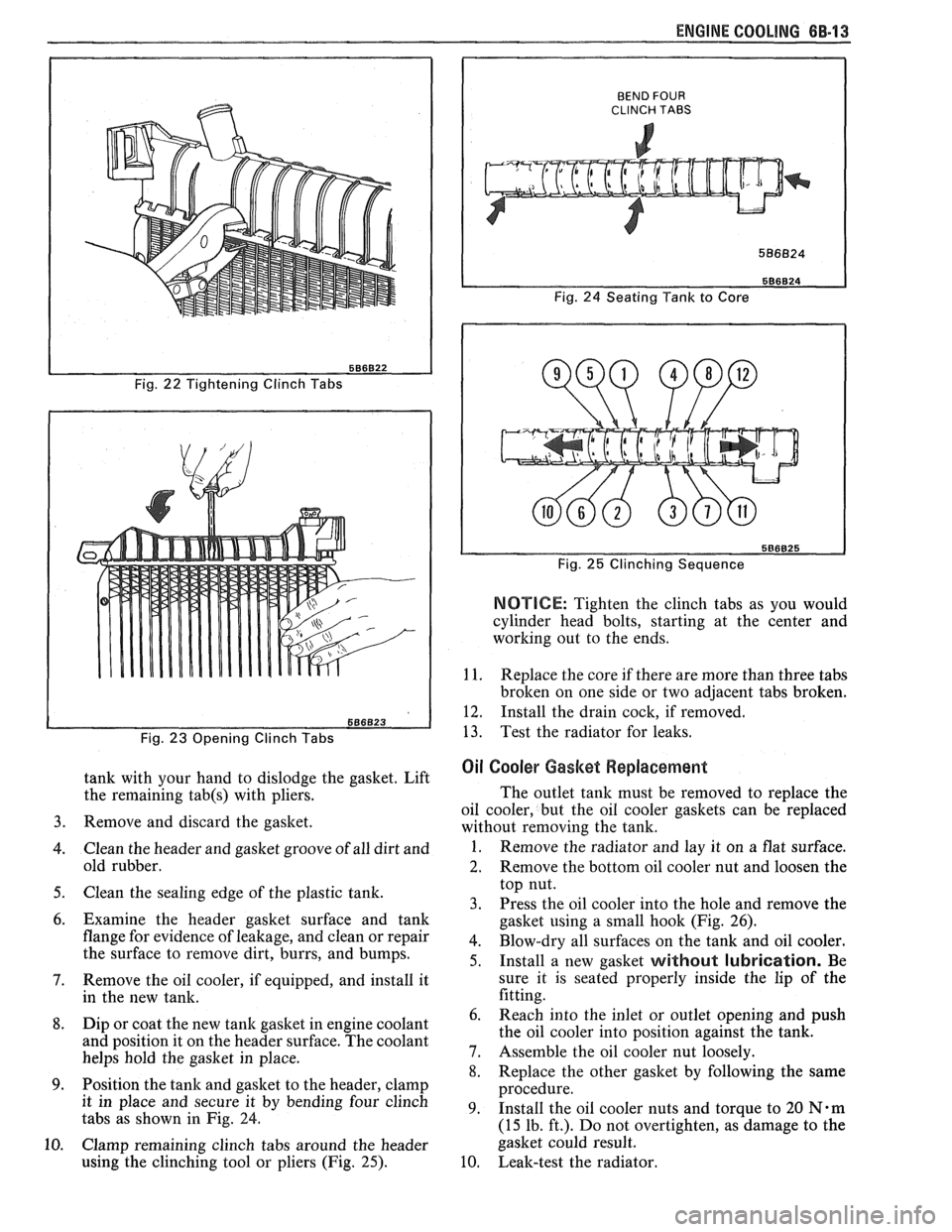
Fig. 22 Tightening Clinch Tabs
Fig.
23 Opening Clinch Tabs
tank with your hand to dislodge the gasket. Lift
the remaining
tab(s) with pliers.
Remove and discard the gasket.
Clean the header and gasket groove of all dirt and
old rubber.
Clean the sealing edge of the plastic tank.
Examine the header gasket surface and tank
flange for evidence of leakage, and clean or repair
the surface to remove dirt, burrs, and bumps.
Remove the oil cooler, if equipped, and install it
in the new tank.
Dip or coat the new
tank gasket in engine coolant
and position it on the header surface. The coolant
helps hold the gasket in place.
Position the tank and gasket to the header, clamp
it in place and secure it by bending four clinch
tabs as shown
in Fig. 24.
Clamp remaining clinch tabs around the header
using the clinching tool or pliers (Fig.
25).
BEND FOUR CLINCH TABS
Fig. 24 Seating Tank to Core
Fig.
25 Clinching Sequence
NOTICE: Tighten the clinch tabs as you would
cylinder head bolts, starting at the center and
working out to the ends.
1 1. Replace the core if there are more than three tabs
broken on one side or two adjacent tabs broken.
12. Install the drain cock, if removed.
13. Test the radiator for leaks.
Oil Cooler Gasket Replacement
The outlet tank must be removed to replace the
oil cooler, but the oil cooler gaskets can be replaced
without removing the tank.
1. Remove the radiator and lay it on a flat surface.
2. Remove the bottom oil cooler nut and loosen the
top nut.
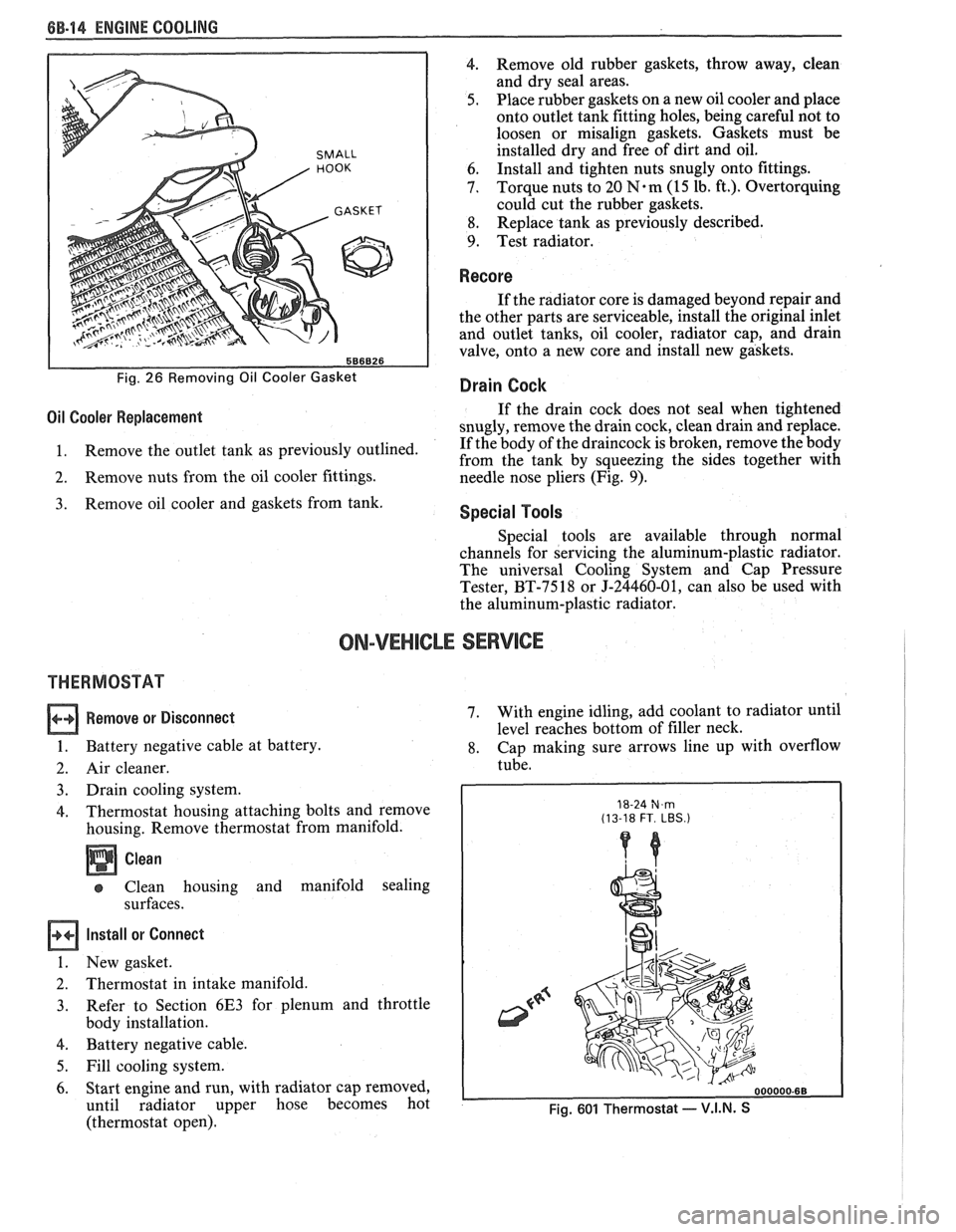
3. Press the oil cooler into the hole and remove the
gasket using a small hook (Fig. 26).
4. Blow-dry all surfaces on the tank and oil cooler.
5. Install a new gasket without lubrication. Be
sure it is seated properly inside the lip of the
fitting.
Reach into the inlet or outlet opening and push
the oil cooler into position against the tank.
Assemble the oil cooler nut loosely.
Replace the other gasket by following the same
procedure.
Install the oil cooler nuts and torque to
20 N.m
(15 lb. ft.). Do not overtighten, as damage to the
gasket could result.
Leak-test the radiator.
Page 425 of 1825
6B-I4 ENGINE COOLING
SMALL
586826
Fig. 26 Removing Oil Cooler Gasket
4. Remove old rubber gaskets, throw away, clean
and dry seal areas.
5. Place rubber gaskets on a new oil cooler and place
onto outlet tank fitting holes, being careful not to
loosen or misalign gaskets. Gaskets must be
installed dry and free of dirt and oil.
6. Install
and tighten nuts snugly onto fittings.
7. Torque nuts
to 20
N.m (15 lb. ft.). Overtorquing
could cut the rubber gaskets.
8. Replace
tank as previously described.
9. Test radiator.
Recore
If the radiator core is damaged beyond repair and
the other parts are serviceable, install the original inlet
and outlet tanks, oil cooler, radiator cap, and drain
valve, onto a new core and install new gaskets.
Drain Cock
Oil Cooler Replacement If the drain cock does not seal when tightened
snugly, remove the drain cock, clean drain and replace.
1. Remove
the outlet tank as previously outlined. If
the body of the draincock is broken, remove the body
from the tank by squeezing the sides together with
2. Remove nuts from the oil cooler fittings.
needle nose pliers (Fig. 9).
Remove oil cooler and gaskets from tank. Special Tools
Special tools are available through normal
channels for servicing the aluminum-plastic radiator.
The universal Cooling System and Cap Pressure
Tester, BT-7518 or J-24460-01, can also be used with
the aluminum-plastic radiator.
ON-VEHICLE SERVICE
THERMOSTAT
Remove or Disconnect
1. Battery negative cable at battery.
2. Air cleaner.
3. Drain cooling system.
4. Thermostat housing attaching bolts and remove
housing. Remove thermostat from manifold.
Clean
Clean housing and manifold sealing
surfaces.
Install or Connect
1. New gasket.
2. Thermostat in intake manifold.
3. Refer
to Section 6E3 for plenum and throttle
body installation.
4. Battery negative cable.
5. Fill cooling system.
6. Start engine and run, with radiator cap removed,
until radiator upper hose becomes hot
(thermostat open). 7.
With
engine idling, add coolant to radiator until
level reaches bottom of filler neck.
8. Cap making sure arrows line up with overflow
tube.
18-24 N,m (13-18 FT. LBS.)
Fig. 601 Thermostat - V.I.N. S
Page 436 of 1825
ENGINE FUEL CC-5
FUEL TANK
Draining Fuel Tank
1. Disconnect the negative battery cable. Also have
a dry chemical (Class B) fire extinguisher near the
work area.
2. Use a hand operated pump device when possible
to drain as much fuel through the filler tube as
possible.
3. If
a hand operated pump device cannot be used
to complete the draining process, use a siphon at
the main (not return) fuel pipe at the fuel pump
or the fuel tank gage unit.
CAUTION: Never drain or store
gasoline in an open container due to
the possibility of fire or explosion.
4. Reinstall any removed hoses, lines and cap.
Removing Fuel Tank
1. Remove all fuel, see "Draining Fuel Tank".
2. Support
fuel tank and disconnect the two fuel
tank retaining straps.
3. Lower tank enough to disconnect sending unit
wire, hoses, and ground strap, if so equipped.
4. Remove tank from vehicle.
5. Remove sending unit.
Installing Fuel Tank
1. Reverse removal procedure.
2. Always replace "0" ring when tank unit has been
removed.
3. When reinstalling fuel tank, be sure to reinstall
anti-squeak pieces on top of the tank to reduce
rattles and other annoying noises.
4. Tighten fuel tank retaining strap bolts or screws.
Fuel System Cleaning
CAUTION: This procedure will NOT
remove all fuel vapor. Do not attempt
any repair
on tank or filler neck where
heat or flame is required, as an
explosion resulting in personal injury
could occur.
If trouble is due to contaminated fuel or foreign
material that is in the tank, it can usually be cleaned.
If tank is rusted internally, it should be replaced.
1. Disconnect negative battery cable.
2. Disconnect ignition engine harness connector.
Have dry chemical (Class B) fire extinguisher
near the work area.
3. Relieve fuel system pressure.
4. Drain fuel tank (see "Draining Fuel Tank").
5. Remove fuel tank (see "Fuel Tank Removal").
6. Remove external fuel filter and inspect for
contamination. If filter is plugged, replace.
7. Locate tank away from heat, flame, or other
source of ignition. Remove fuel gage sending unit
and fuel pump assembly, if so equipped, and
inspect condition of strainer. If strainer is
contaminated, a new strainer should be installed.
8. Complete draining of tank by rocking it and
allowing fuel to run out of fuel sending unit
opening.
9. Flush fuel tank with running hot water for at least
five minutes. Pour water out of fuel sending unit
opening. (Rock tank to be sure that removal of
water is complete.)
10. Disconnect fuel feed pipe and use air pressure to
clean fuel line. Apply air pressure in the opposite
direction fuel normally flows through the line. On
vehicles equipped with a fuel return line, clean
line in similar manner. Disconnect pipe at
throttle body unit and apply air pressure to clean
return line. Reconnect and torque all pipes to 30
N-m (22 1b. ft.).
11. Use low air pressure to clean pipes on fuel gage
sending unit.
112. Install new strainer on fuel gage sending unit, if
required. Install fuel gage sending unit and fuel
pump, with new gasket, into tank and install fuel
tank. Connect fuel gage wire harness to body
harness. Connect all fuel lines except feed line to
external fuel filter.
13. Disconnect fuel feed hose to chassis pipe at front.
Connect a hose to front end of chassis fuel feed
pipe and insert other end of hose into a one gallon
fuel can.
14. Connect battery cable.
15. Put six gallons of clean fuel into fuel tank and
apply 12 volts to Terminal
"G" of ALCL to
operate fuel pump. Pump two quarts of fuel into
fuel can. This will purge fuel pump.
16. Remove hose and connect fuel hose to chassis
pipe.
17. Check all connections
for leaks; tighten all hose
clamps.
Fuel Tank Purging Procedure
The following procedure is used prior to repairing
of fuel tank.
1. Remove fuel sending unit and fuel pump and
drain all remaining fuel from tank.
2. Visually inspect interior cavity of tank. If any fuel
is evident, drain again.
3. Move tank to flushing area (wash rack).
4. Fill tank completely with tap water, agitate
vigorously and drain.
5. Add gasoline emulsifying agent to the tank, refill
with water, agitate mixture for 10 minutes, and
drain tank completely.
For correct gasoline emulsifying agent-to-water
mixture, refer to the
manufacturer's
specifications. Use an available emulsifying
agent, such as "Product-Sol No.
913", or
equivalent.
6. When empty, refill the tank to overflowing with
water. Completely flush out remaining mixture
and empty tank.
7. If available, an explosion meter should be used Lo
check for negative reading.
8. Perform required service work.