1988 PONTIAC FIERO drain bolt
[x] Cancel search: drain boltPage 281 of 1825
4B-8 REAR AXLE
GENERAL lNFORMATlON
A universal joint connects the rear end of the
propeller shaft to a pinion flange, having a splined end
which fits over and drives the
hypoid pinion gear. The
housing is attached to the underbody through a center
bearing support. Inside the housing, an extension shaft
is splined to the drive pinion at the rear end, and to the
companion flange at the other end. Two pre-loaded
tapered roller bearings support the
hypoid pinion gear
in the carrier. The inner race of the rear bearing is a
light press fit on the pinion stem. The inner race of the
front bearing combines a light press fit to a close sliding
fit on the pinion flange end of the pinion stem. The
outer race of each bearing is pressed against a shoulder
recessed in the carrier. Tightening the pinion nut
compresses a collapsible spacer which bears against the
inner race of the front bearing and a shoulder on the
pinion stem. This spacer is used to enable accurate
bearing pre-load adjustment and
maintain a pre-load
on both front and rear pinion bearings. Adjustment of the
fore and aft position of the pinion is obtained by
placing
shims between the head of the drive pinion and
the rear pinion bearing.
The rear axle case is of
one-piece construction and is supported in the carrier
by two tapered roller side bearings. These are
pre-loaded by inserting
shims between the bearings and
the carrier. The rear axle case assembly is positioned
for proper ring gear to pinion backlash by varying the
shin1 thickness from side to side. The ring gear is bolted
to the case. Two side gears have splined bores for
driving the axle shafts. They are positioned to turn in
counterbored cavities in the case. The two rear axle
pinions have
smooth bores and are held in position by
a solid pinion cross shaft, mounted and locked in the
rear axle case. All four gears are in
mesh with each
other and because the pinion gears turn freely
on their
shaft, they act as idler gears when the rear wheels are
turning at different speeds. The pinions and side gears
are backed by steel thrust washers.
LIMITED-SLIP REAR AXLE
The operation of the Limited-Slip differential is
the same as the standard differential, except that there
is additional friction provided by the clutches or cones.
Under ordinary driving and cornering conditions, the
clutches or cones slip, allowing the outside wheel to
turn faster than the inner. Under poor traction
conditions, such as ice, snow, or loose gravel under one
driving wheel, the increased friction provided by the clutches
or cones increases the driving torque available
to the wheel with the better traction. The clutches or
cones are spring loaded to provide the increased
driving torque under extremely low traction
conditions.
Most rear axle service repairs can be made with
the rear axle assembly in the car, by raising the rear end
of the car with the rear axle hanging
on the shock
absorbers.
ON-VEHICLE SERVICE
CARRIER COVER AND GASKET
Remove or Disconnect
1. Having a container in place, remove cover bolts
and pry cover loose to drain lubricant.
2. Make sure both gasket sealing surfaces are clean.
Install or Connect
Use sealant
1052366 or cover gasket
only.
1. Torque cover bolts in a crosswise pattern to
insure uniform draw on gasket. Torque
27 N.m
(20 Ib.fr.).
2. Fill with lubricant to a level within 4.5mm (3116")
or filler plug hole. Refer to specifications for correct
lubricant usage and quantity.
Axle Shaft
a Remove or Disconnect
1. Raise car and remove wheel and brake drum.
2. Clean all dirt from area of carrier.
3. Remove bolts and differential carrier cover and
allow lubricant to drain.
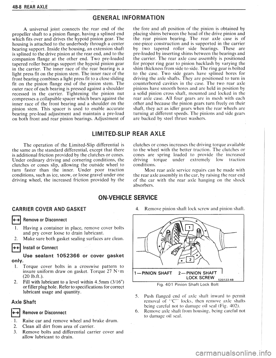
4. Remove pinion shaft lock screw and pinion shaft.
1 -PINION SHAFT 2-PINION SHAFT 1
SCREW 520122 48
Fig. 401 Pinion Shaft Lock Bolt
5. Push flanged end of axlc shalt inward to pcrmil
removal of "C" locks, thcn rcmovc axlc shafts
being
careful not to cl;uii~~gc oil scal (Fig. 402).
6. Remove axlc shaft from housing, bcing curcl'ul not
to
damage oil scal.
Page 284 of 1825
REAR AXLE 48-1 1
Rear Wheel Bolt
Remove or Disconnect 1.
1. Raise vehicle on hoist allowing axle to hang
freely. 2.
2. Remove
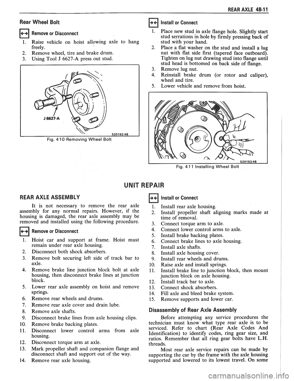
wheel, tire and brake drum.
3. Using Tool J 6627-A press out stud.
Fig. 4 10 Removing Wheel Bolt
REAR AXLE ASSEMBLY
Install or Connect
Fig. 4 11 Installing Wheel Bolt
UNIT REPAIR
Remove or Disconnect
Place new stud in axle flange hole. Slightly start
stud serrations in hole by firmly pressing back of
stud with your hand.
Place a flat washer on the stud and install a lug
nut with flat side first (tapered face outboard).
Tighten on lug nut drawing stud into flange until
stud head is bottomed on back side of flange.
Remove lug nut.
Reinstall brake drum (or rotor and caliper),
wheel and tire.
Lower vehicle and remove from hoist.
It is not necessary to remove the rear axle
assembly for any normal repairs. However, if the
housing is damaged, the rear axle assembly may be
removed and installed using the following procedure.
Hoist car and support at frame. Hoist must
remain under rear axle housing.
Disconnect both shock absorbers.
Remove bolt securing left side of track bar to
axle.
Remove brake line junction block bolt at axle
housing, then disconnect brake lines at junction
block.
Lower rear axle assembly on hoist and remove
springs.
Remove rear wheels and drums.
Remove rear axle cover and drain lube.
Remove axle shafts.
Disconnect brake lines from axle housing clips.
Remove brake backing plates.
Disconnect lower control arms from axle
housing.
Disconnect torque arm at axle.
Mark propeller shaft and companion flange and
disconnect shaft and support out of the way.
Remove rear axle housing.
Install or Connect
Install rear axle housing.
Install propeller shaft aligning marks made at
time of removal.
Connect torque arm to axle.
Connect lower control arms to axle.
Install brake backing plates.
Connect brake lines to axle housing.
Install axle shafts.
Install axle housing cover.
Install rear wheels and drums.
Raise axle and install springs.
Install brake line to junction block, then mount
junction block on axle housing.
Install track bar to axle.
Connect shock absorbers.
Fill axle and bleed brake system.
Remove supports and lower car.
Disassembly of Rear Axle Assembly
Before attempting any service procedures the
technician must know what type rear axle is to be
serviced. Refer to chart (Rear Axle Codes And
Identification) to identify codes, ring gear size, and
ratios. Remember that all ring gear bolts have L.H.
threads.
Most rear axle service repairs can be made by
supporting the car by the frame with the axle housing
supported and lowered to its lowest travel. On some
Page 285 of 1825
48-1 2 REAR AXLE
models it may be necessary to disconnect shock
absorbers to obtain additional clearance. When doing
this, do not allow the rear brake hose to become kinked
or stretched.
Lubricant may be drained by backing out all
cover bolts and breaking cover loose at the bottom.
If the rear axle housing is removed for any reason,
rear axle service can be performed on the bench.
When a new ring gear and pinion is installed, the
owner should be advised not to accelerate rapidly or
exceed
50 mph for the first 50 miles of driving.
Case Assembly
Remove or Disconnect
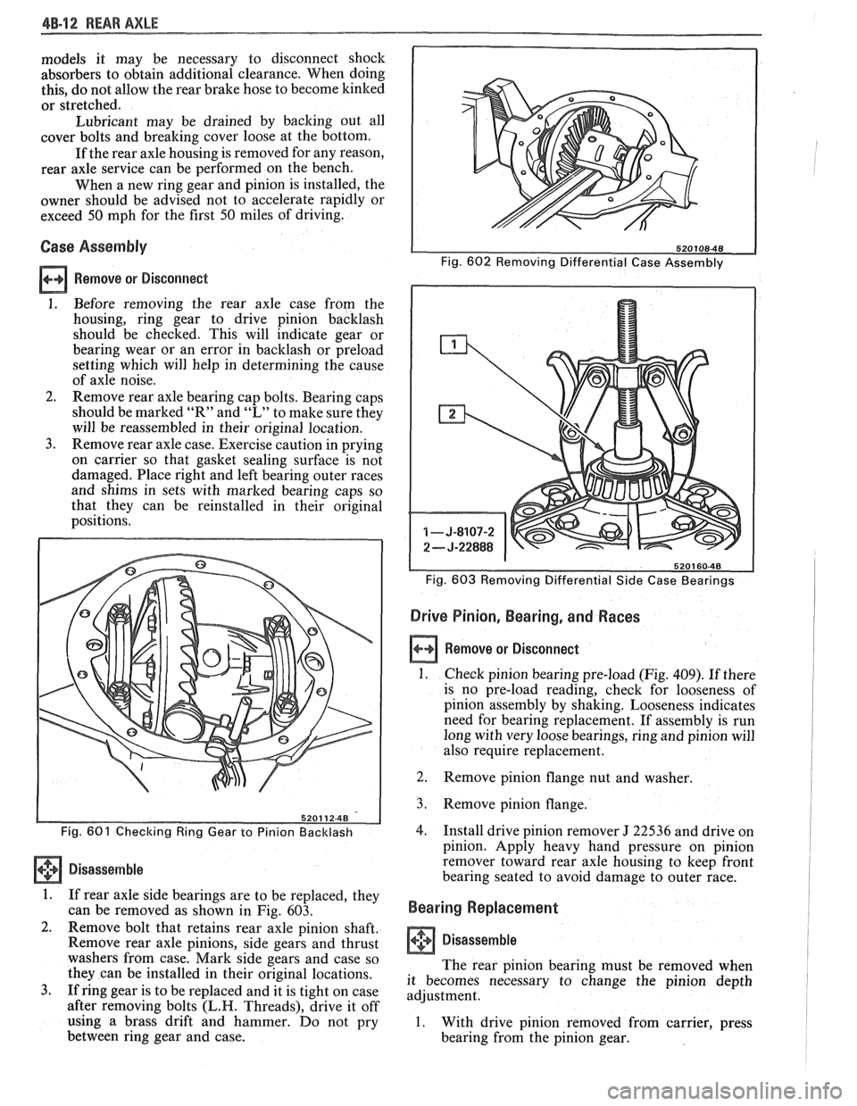
1. Before removing the rear axle case from the
housing, ring gear to drive pinion backlash
should be checked. This will indicate gear or
bearing wear or an error in backlash or preload
setting which will help in determining the cause
of axle noise.
2. Remove rear axle bearing cap bolts. Bearing caps
should be marked
"It" and "L" to make sure they
will be reassembled in their original location.
3. Remove rear axle case. Exercise caution in prying
on carrier so that gasket sealing surface is not
damaged. Place right and left bearing outer races
and shims in sets with marked bearing caps so
that they can be reinstalled in their original
positions.
Fig. 603 Removing Differential Side Case Bearings
Drive Pinion, Bearing, and Races
a Remove or Disconnect
1. Check pinion bearing pre-load (Fig. 409). If there
is no pre-load reading, check for looseness of
pinion assembly by shaking. Looseness indicates
need for bearing replacement. If assembly is run
long with very loose bearings, ring and pinion will
also require replacement.
Fig. 601 Checking Ring Gear to Pinion Backlash
Disassemble
1. If rear axle side bearings are to be replaced, they
can be removed as shown in Fig. 603.
2. Remove bolt that retains rear axle pinion shaft.
Remove rear axle pinions, side gears and thrust
washers from case. Mark side gears and case so
they can be installed in their original locations.
3. If ring gear is to be replaced and it is tight on case
after removing bolts
(L.H. Threads), drive it off
using a brass drift and hammer. Do not pry
between ring gear and case. 2.
Remove pinion flange
nut and washer.
3. Remove pinion flange.
4. Install drive pinion remover J 22536 and drive on
pinion. Apply heavy hand pressure on pinion
remover toward rear axle housing to keep front
bearing seated to avoid damage to outer race.
Bearing Replacement
I Disassemble
The rear pinion bearing must be removed when
it becomes necessary to change the pinion depth
adjustment.
1. With drive pinion removed from carrier, press
bearing from the pinion gear.
Page 348 of 1825
ENGINE GENERAL INFORMATION 6-3
B, Section 6E2 - Fuel Injection (TBI)
B, Section 6E3 - Fuel Injection (Ported)
ENGINE MECHANICAL DIAGNOSIS
The following diagnostic information covers common problems and possible causes. When
the proper diagnosis is made, the problem should be corrected by adjustment, repair or part
replacement as required. Refer to the appropriate section of the manual for these procedures.
EXCESSIVE OIL LOSS
B, External oil leaks. Tighten bolts and/or replace o Continuous high speed driving, and/or severe
gaskets and seals as necessary. usage
such as trailer hauling, will normally cause
decreased oil mileage.
e Improper reading of dipstick. Check oil with car PCV system malfunctioning. on a level surface and allow adequate drain-down Valve guides and/or valve stem seals worn, or time.
seals omitted. Ream guides and install oversize
service valves and/or new valve stem seals.
Improper Use S.A'E' Piston rings broken, worn, or not seateded. Allow viscosity for prevailing temperatures. See
adequate time for rings to seat. Replace broken
Owner's Manual for proper specifications.
or worn rings, as necessary.
Piston improperly installed or misfitted.
LOW OIL PRESSURE
Slow idle speed. Set idle speed to correct
specification, if not ECM controlled.
Incorrect, or malfunctioning, oil pressure switch.
Incorrect, or malfunctioning, oil pressure gage.
Replace with proper gage.
.*
Improper oil viscosity, or diluted oil. install oil of
proper viscosity for expected temperature, or
install new oil if diluted with moisture or
unburned fuel mixtures.
o Oil pump worn or dirty.
e Plugged oil filter.
e Oil pickup screen loose or plugged.
B, Hole in oil pickup tube.
e Excessive bearing clearance. Replace if necessary.
o Cracked, porous or plugged oil galleys. Repair or
replace block.
o Galley plugs missing or misinstalled. Install
plugs, or repair as necessary.
VALVE TRAIN NOISE
e Low oil pressure. Repair as necessary. (See o Broken valve spring.
preceding diagnosis for low oil pressure.)
o Sticking valves.
o Loose rocker arm attachments. Inspect and B, Lifters worn, dirty, or defective. Clean, inspect,
test and replace as necessary.
repair as necessary.
o Camshaft worn, or poor machining. Replace
o Worn rocker arm and/or pushrod. camshaft.
B, Worn valve guides.
ENGINE KNOCK DIAGNOSIS
KNOCKS COLD AND CONTINUES FOR TWO TO THREE MINUTES
INCREASES
WITH TORQUE
o Vacuum operated EFE engines may have valve o Excessive piston to bore clearance. Replace
knock. Replace EFE valve. piston.
e Flywheel contacting splash shield. Reposition
splash shield.
e Loose or broken balancer or drive pulleys.
Tighten, or replace as necessary. Cold engine piston knock usually
disappears when the cylinder is grounded
out. Cold engine piston knock which
disappears in 1.5 minutes should be
considered acceptable.
Page 360 of 1825
2.8 LITER V-6 6A2-9
INTAKE MANIFOLD (FIGURE 6A2-7)
Removal
Disconnect battery.
Remove air cleaner.
Drain coolant.
Refer to Section 6E3 for removal of the following
PFI sub-assemblies.
e Plenum
e Fuel Rail
e Runner
Disconnect spark plug wires at spark plugs.
Disconnect wires at coil.
Remove distributor cap and spark plug wires.
Mark distributor position and remove hold down
bracket.
Remove distributor.
Remove air management hose, manual
transmission only.
Disconnect emission canister hoses. Remove pipe
bracket (front left valve cover).
Remove left valve cover.
Remove air management bracket, manual
transmission only.
Remove right valve cover.
Remove upper radiator hose.
Disconnect heater hose.
Disconnect coolant switches.
Remove manifold bolts.
Remove manifold. Discard manifold gaskets and
remove loose RTV from front and rear ridges of
cylinder case.
Installation
When installing intake gaskets, notice that the
gaskets are marked Right Side and Left Side
(carbureted only). Use them only as indicated to
maintain designed efficiency of this engine.
1. Make
sure that no oil or water is present on
surface when new RTV is applied. Place a 5mm
diameter
(3/16") bead of RTV, # 1052917 or
equivalent, on each ridge.
2. Install
new intake gaskets on cylinder heads.
Hold in place by extending ridge RTV bead up
6mm onto the gasket ends. The new intake
gaskets will have to be cut, where indicated, to
install behind push rods. Cut only those areas
that are necessary.
3. Install intake
manifold on engine. Make sure
areas between case ridges and intake are
completely sealed.
4. Install manifold retaining bolts and nuts and
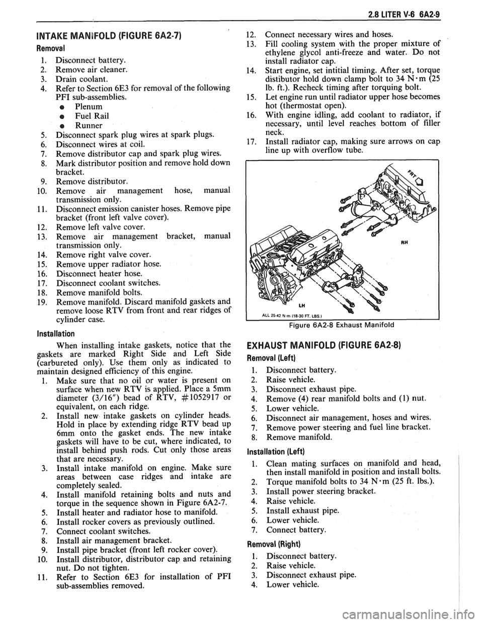
torque in the sequence shown in Figure 6A2-7.
5. Install heater and radiator hose to manifold.
6. Install rocker covers as previously outlined.
7. Connect coolant switches.
8. Install air management bracket.
9. Install pipe bracket (front left rocker cover).
10. Install distributor, distributor cap and retaining
nut. Do not tighten.
11. Refer to Section 6E3 for installation of PFI
sub-assemblies removed. 12.
Connect
necessary wires and hoses.
13. Fill cooling system with
the proper mixture of
ethylene glycol anti-freeze and water. Do not
install radiator cap.
14. Start
engine, set intitial timing. After set, torque
distibutor hold down clamp bolt to 34
N-m (25
lb. ft.). Recheck timing after torquing bolt.
15. Let engine
run until radiator upper hose becomes
hot (thermostat open).
16. With
engine idling, add coolant to radiator, if
necessary, until level reaches bottom of filler
neck.
17. Install
radiator cap, making sure arrows on cap
line up with overflow tube.
Figure 6A2-8 Exhaust Manifold
EXHAUST MANIFOLD (FIGURE 6A2-8)
Removal (Left)
1. Disconnect battery.
2. Raise vehicle.
3. Disconnect exhaust pipe.
4. Remove
(4) rear manifold bolts and (1) nut.
5. Lower vehicle.
6. Disconnect air management, hoses and wires.
7. Remove power steering and fuel line bracket.
8. Remove manifold.
Installation (Left)
1. Clean mating surfaces on manifold and head,
then install manifold in position and install bolts.
2. Torque
manifold bolts to 34
N.m (25 ft. lbs.).
3. Install power steering bracket.
4. Raise vehicle.
5. Install exhaust pipe.
6. Lower vehicle.
7. Connect battery.
Removal (Right)
1. Disconnect battery.
2. Raise vehicle.
3. Disconnect exhaust pipe.
4. Lower vehicle.
Page 363 of 1825
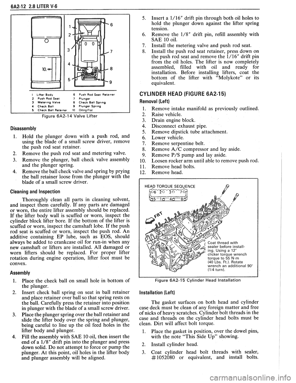
I Liher Body 6 Push Rod Seat Reta~ner 2 Push Rod Seal 7 Plunger 3 Mater~ng Valve 8 Check Ball Spr~ng 4 Check Ball 9 Plunger Spr~ng 5 Check Ball Rete~ner 10 Olllna Flat
Figure 6A2-14 Valve Lifter
Disassembly
1. Hold the plunger down with a push rod, and
using the blade of a small screw driver, remove
the push rod seat retainer.
2. Remove the push rod seat and metering valve.
3. Remove the plunger, ball check valve assembly
and the plunger spring.
4. Remove the ball check valve and spring by prying
the ball retainer loose from the plunger with the
blade of a small screw driver.
Cleaning and Inspection
Thoroughly clean all parts in cleaning solvent,
and inspect them carefully. If any parts are damaged
or worn, the entire lifter assembly should be replaced.
If the lifter body wall is scuffed or worn, inspect the
cylinder block lifter bore. If the bottom of the lifter is
scuffed or worn, inspect the camshaft lobe. If the push
rod seat is scuffed or worn, inspect the push rod. An
additive containing EP lube, such as EOS, should
always be added to crankcase oil for run-in when any
new camshaft or lifters are installed. All damaged or
worn lifters should be replaced. For proper lifter
rotation during engine operation, lifter foot must be
convex.
Assembly
1. Place
the check ball on small hole in bottom of
the plunger.
2. Insert
check ball spring on seat in ball retainer
and place retainer over ball so that spring rests on
the ball. Carefully press the retainer into position
in plunger with the blade of a small screw driver.
3. Place the plunger spring over the ball retainer and
slide the lifter body over the spring and plunger,
being careful to line up the oil feed holes in the
lifter body and plunger.
4. Fill the assembly with SAE 10 oil, then insert the
end of a
1/8" drift pin into the plunger and press
down solid. Do not attempt to force or pump the
plunger. At this point, oil holes in the lifter body
and plunger assembly will be aligned.
5. Insert a 1/16" drift pin through both oil holes to
hold the plunger down against the lifter spring
tension.
6. Remove
the
1/8" drift pin, refill assembly with
SAE 10 oil.
7. Install the metering valve and push rod seat.
8. Install the push rod seat retainer, press down on
the push rod seat and remove the 1/16" drift pin
from the oil holes. The lifter is now completely
assembled, filled with oil and ready for
installation. Before installing lifters, coat the
bottom of the lifter with "Molykote" or its
equivalent.
CYLINDER HEAD (FIGURE 6A2-15)
Removal (Left)
Remove intake manifold as previously outlined.
Raise vehicle.
Drain engine block.
Disconnect exhaust pipe.
Remove dipstick tube attachment.
Lower vehicle.
Remove serpentine belt.
Remove A/C compressor and lay aside.
Remove
P/S pump and lay aside.
Loosen rocker arm until able to remove push rod.
Remove head bolts.
Remove head.
HEAD TORQUE SEQUENCE
/7 , 2 ing. Using a 12"
Figure 6A2-1'5 Cylinder Head Installation
Installation (Left)
The gasket surfaces on both head and cylinder
case deck must be clean of any foreign matter and free
of nicks of heavy scratches. Cylinder bolt threads in the
case and threads on the cylinder head bolts must be
clean. Dirt will affect bolt torque.
1. Place the gasket in position, over the dowel pins,
with the note "This Side Up" showing.
2. Install cylinder head.
3. Coat cylinder head bolt threads with sealer,
#1052080 or equivalent, and install bolts.
Page 364 of 1825
2.8 LITER V.6 6A2.13
Torque bolts as shown in Figure 6A2-15.
4. Install
push rods and loosely retain with rocker
arms. Make sure lower ends of
pushrods are in
lifter seats.
5. Install intake manifold.
6. Raise vehicle.
7. Install dipstick tube bracket.
8. Connect exhaust pipe
to exhaust manifold flange.
9. Lower vehicle.
10. Adjust
valve lash as previously outlined.
11. Continue
following intake manifold installation
for build up.
Removal (Right)
Remove intake manifold as previously outlined.
Raise vehicle.
Disconnect exhaust pipe.
Drain engine block.
Lower vehicle.
Loosen rocker arms until able to remove push
rod.
Remove serpentine belt.
Remove tensioner.
Remove A.I.R. bracket.
Remove generator bracket.
Remove head bolts.
Remove head.
Installation (Right)
The gasket surfaces on both the head and cylinder
case
deck must be clean of any foreign matter and free
of nicks of heavy scratches. Cylinder bolt threads in the
case and threads on the cylinder head bolts must be
clean. Dirt will affect bolt torque.
1. Place the gasket in position, over the dowel pins,
with the note "This Side Up" showing.
2. Install cylinder head.
3. Coat cylinder head bolt threads with sealer,
#lo52080 or equivalent, and install bolts.
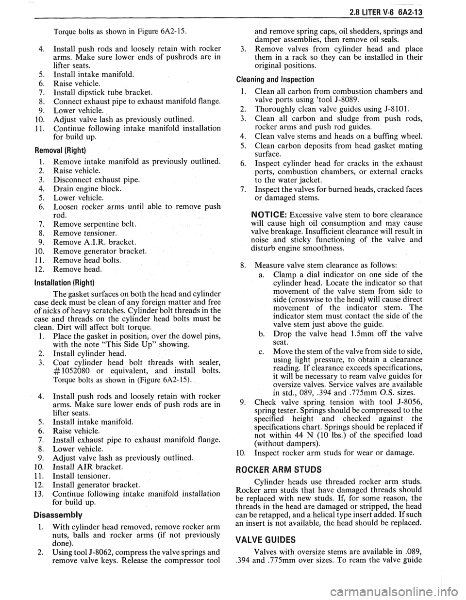
Torque bolts as shown in (Figure
6A2-15).
Install push rods and loosely retain with rocker
arms. Make sure lower ends of push rods are in
lifter seats.
Install intake manifold.
Raise vehicle.
Install exhaust pipe to exhaust manifold flange.
Lower vehicle.
Adjust valve lash as previously outlined.
Install AIR bracket.
Install tensioner.
Install generator bracket.
Continue following intake manifold installation
for build up.
Disassembly
1. With cylinder head removed, remove rocker arm
nuts, balls and rocker arms (if not previously
done).
2. Using tool J-8062, compress the valve springs and
remove valve keys. Release the compressor tool and
remove spring caps, oil shedders, springs and
damper assemblies, then remove oil seals.
3. Remove valves from cylinder head and place
them in a rack so they can be installed in their
original positions.
Cleaning and Inspection
Clean all carbon from combustion chambers and
valve ports using 'tool
5-8089.
Thoroughly clean valve guides using 5-8 10 1.
Clean all carbon and sludge from push rods,
rocker arms and push rod guides.
Clean valve stems and heads on a buffing wheel.
Clean carbon deposits from head gasket mating
surface.
Inspect cylinder head for cracks in the exhaust
ports, combustion chambers, or external cracks
to the water jacket.
Inspect the valves for burned heads, cracked faces
or damaged stems.
NOTICE: Excessive valve stem to bore clearance
will cause high oil consumption and may cause
valve breakage. Insufficient clearance will result in
noise and sticky functioning of the valve and
disturb engine smoothness.
8. Measure valve stem clearance as follows:
a. Clamp
a dial indicator on one side of the
cylinder head. Locate the indicator so that
movement of the valve stem from side to
side (crosswise to the head) will cause direct
movement of the indicator stem. The
indicator stem must contact the side of the
valve stem just above the guide.
b. Drop
the valve head
1.5mm off the valve
seat.
c. Move
the stem of the valve from side to side,
using light pressure, to obtain a clearance
reading. If clearance exceeds specifications,
it will be necessary to ream valve guides for
oversize valves. Service valves are available
in std., 089,
.394 and .775mm O.S. sizes.
9. Check
valve spring tension with tool J-8056,
spring tester. Springs should be compressed to the
specified height and checked against the
specifications chart. Springs should be replaced if
not within 44
N (10 Ibs.) of the specified load
(without dampers).
10. Inspect
rocker arm studs for wear or damage.
ROCKER ARM STUDS
Cylinder heads use threaded rocker arm studs.
Rocker arm studs that have damaged threads should
be replaced with new studs. If, for some reason, the
threads in the head
are damaged or stripped, the head
can be retapped, and a helical type insert added. If such
an insert is not available, the head should be replaced.
VALVE GUIDES
Valves with oversize stems are available in .089,
,394 and ,775mm over sizes. To ream the valve guide
Page 368 of 1825
2.8 LITER V-6 6A2-17
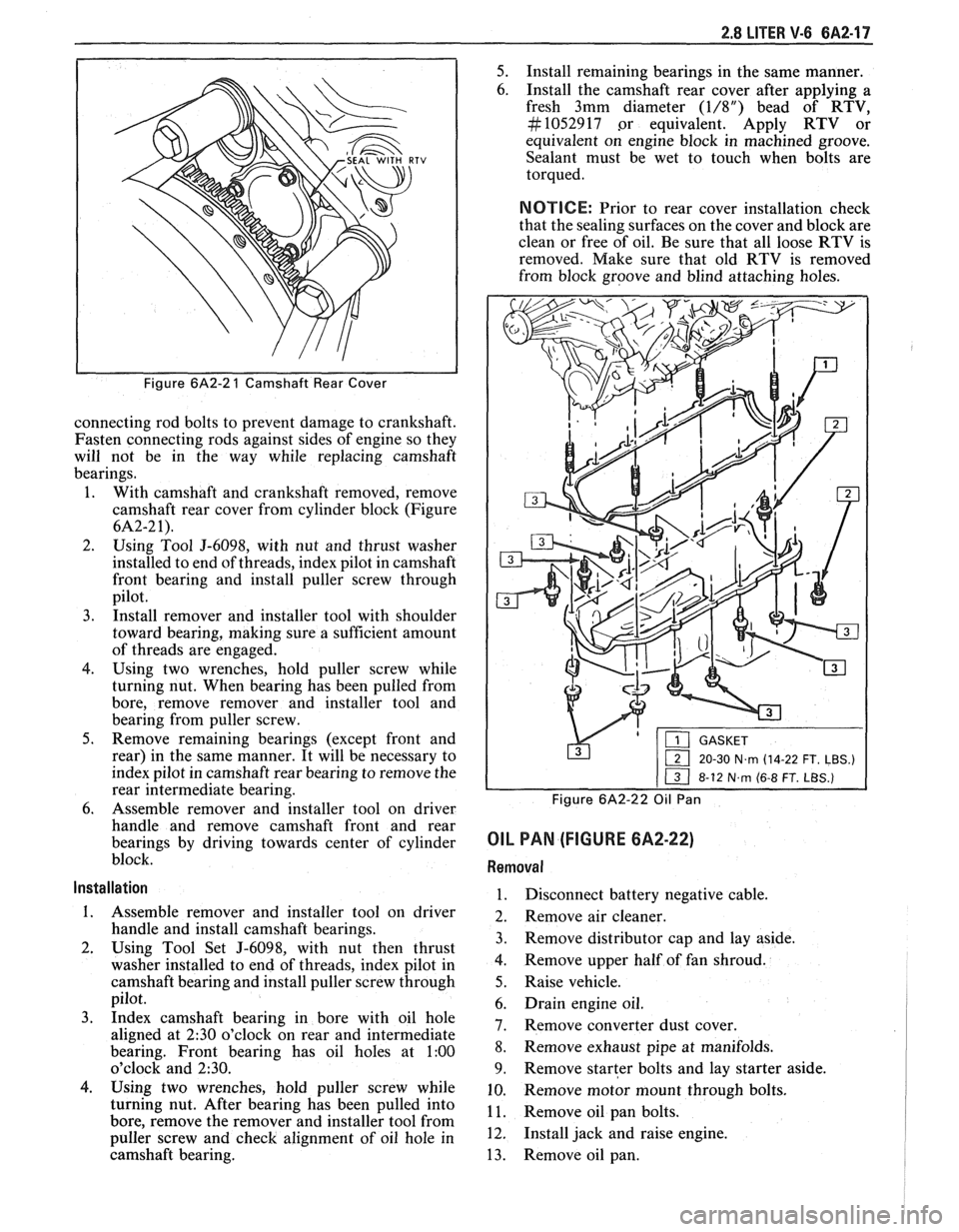
Figure 6A2-2 1 Camshaft Rear Cover
connecting rod bolts to prevent damage to crankshaft.
Fasten connecting rods against sides of engine so they
will not be in the way while replacing camshaft
bearings.
1. With camshaft and crankshaft removed, remove
camshaft rear cover from cylinder block (Figure
6A2-2 1).
2. Using Tool J-6098, with nut and thrust washer
installed to end of threads, index pilot in camshaft
front bearing and install puller screw through
pilot.
3. Install remover and installer tool with shoulder
toward bearing, making sure a sufficient amount
of threads are engaged.
4. Using two wrenches, hold puller screw while
turning nut. When bearing has been pulled from
bore, remove remover and installer tool and
bearing from puller screw.
5. Remove remaining bearings (except front and
rear) in the same manner. It will be necessary to
index pilot in camshaft rear bearing to remove the
rear intermediate bearing.
6. Assemble remover and installer tool on driver
handle and remove camshaft front and rear
bearings by driving towards center of cylinder
block.
Installation
1. Assemble remover and installer tool on driver
handle and install camshaft bearings.
2. Using Tool Set J-6098, with nut then thrust
washer installed to end of threads, index pilot in
camshaft bearing and install puller screw through
pilot.
3. Index camshaft bearing in bore with oil hole
aligned at
2:30 o'clock on rear and intermediate
bearing. Front bearing has oil holes at
1:00
o'clock and 230.
4. Using two wrenches, hold puller screw while
turning nut. After bearing has been pulled into
bore, remove the remover and installer tool from
puller screw and check alignment of oil hole in
camshaft bearing.
5. Install remaining bearings in the same manner.
6. Install the camshaft rear cover after applying a
fresh 3mm diameter
(1/8") bead of RTV,
#I052917 .or equivalent. Apply RTV or
equivalent on engine block in machined groove.
Sealant must be wet to touch when bolts are
torqued.
NOTICE: Prior to rear cover installation check
that the sealing surfaces on the cover and block are
clean or free of oil. Be sure that all loose RTV is
removed. Make sure that old RTV is removed
from block groove and blind attaching holes.
&'p-x&F--
1 20-30 N~rn (14-22 FT. LBS.)
Figure 6A2-22 Oil Pan
OIL PAN (FIGURE 6A2-22)
Removal
1. Disconnect battery negative cable.
2. Remove air cleaner.
3. Remove distributor cap and lay aside.
4. Remove upper half of fan shroud.
5. Raise vehicle.
6. Drain engine oil.
7. Remove converter dust cover.
8. Remove exhaust
pipe at manifolds.
9. Remove starter bolts and lay starter aside.
10. Remove
motor mount through bolts.
1 1. Remove oil pan bolts.
12. Install jack and raise engine.
13. Remove oil pan.