1988 PONTIAC FIERO drain bolt
[x] Cancel search: drain boltPage 1142 of 1825
5-SPEED 97MM TRANSMISSION 7B-5
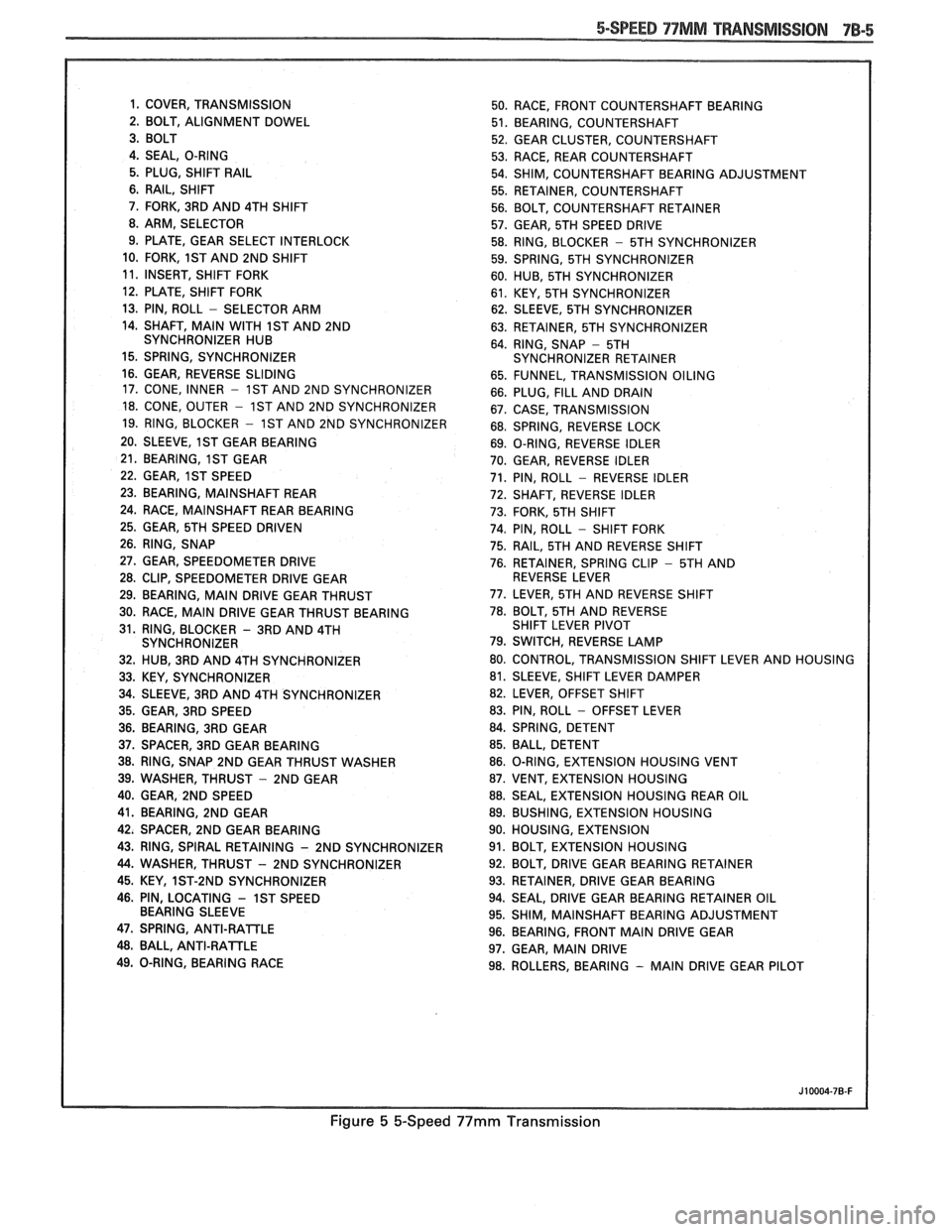
1. COVER, TRANSMISSION
50. RACE, FRONT COUNTERSHAFT BEARING
2. BOLT, ALIGNMENT DOWEL
51. BEARING, COUNTERSHAFT
52. GEAR CLUSTER, COUNTERSHAFT
4. SEAL, O-RING
53. RACE, REAR COUNTERSHAFT
5. PLUG, SHIFT
RAIL 54. SHIM, COUNTERSHAFT BEARING ADJUSTMENT
6. RAIL, SHIFT
55. RETAINER, COUNTERSHAFT
7. FORK, 3RD AND 4TH SHIFT
56. BOLT, COUNTERSHAFT RETAINER
8. ARM, SELECTOR
57. GEAR, 5TH SPEED DRIVE
9. PLATE, GEAR SELECT INTERLOCK
58. RING, BLOCKER
- 5TH SYNCHRONIZER
10. FORK,
1ST AND 2ND SHIFT
59. SPRING, 5TH SYNCHRONIZER
11. INSERT, SHIFT FORK
60. HUB, 5TH SYNCHRONIZER
12. PLATE, SHIFT FORK
61. KEY, 5TH SYNCHRONIZER
13. PIN, ROLL
- SELECTOR ARM
62. SLEEVE, 5TH SYNCHRONIZER
14. SHAFT,
MAIN WITH 1ST AND 2ND
63. RETAINER, 5TH SYNCHRONIZER
SYNCHRONIZER HUB
64. RING, SNAP
- 5TH
15. SPRING, SYNCHRONIZER SYNCHRONIZER RETAINER
16. GEAR, REVERSE SLIDING
65. FUNNEL, TRANSMISSION OILING
17. CONE, INNER
- 1ST AND 2ND SYNCHRONIZER
66. PLUG, FILL AND DRAIN
18. CONE, OUTER - 1ST AND 2ND SYNCHRONIZER
67. CASE, TRANSMISSION
19. RING, BLOCKER
- 1ST AND 2ND SYNCHRONIZER
68. SPRING, REVERSE LOCK
20. SLEEVE,
1ST GEAR BEARING
69. O-RING, REVERSE IDLER
21. BEARING,
1ST GEAR
70. GEAR, REVERSE IDLER
22. GEAR,
1ST SPEED 71. PIN, ROLL - REVERSE IDLER
23. BEARING, MAINSHAFT REAR
72. SHAFT, REVERSE IDLER
24. RACE,
MAINSHAFT REAR BEARING
73. FORK, 5TH SHIFT
25. GEAR, 5TH SPEED DRIVEN
74. PIN, ROLL - SHIFT FORK
26. RING, SNAP
75. RAIL, 5TH AND REVERSE SHIFT
27. GEAR, SPEEDOMETER DRIVE
76. RETAINER, SPRING CLIP - 5TH AND
28. CLIP, SPEEDOMETER DRIVE GEAR REVERSE LEVER
29. BEARING,
MAIN DRIVE GEAR THRUST 77.
LEVER, 5TH AND REVERSE SHIFT
30. RACE,
MAIN DRIVE GEAR THRUST BEARING 78. BOLT, 5TH
AND REVERSE
31. RING, BLOCKER
- 3RD AND 4TH SHIFT
LEVER PIVOT
SYNCHRONIZER 79. SWITCH, REVERSE LAMP
32. HUB, 3RD AND 4TH SYNCHRONIZER 80.
CONTROL, TRANSMISSION SHIFT LEVER AND HOUSING
33. KEY, SYNCHRONIZER 81.
SLEEVE, SHIFT LEVER DAMPER
34. SLEEVE, 3RD AND 4TH SYNCHRONIZER 82.
LEVER, OFFSET SHIFT
35. GEAR, 3RD SPEED 83. PIN, ROLL
- OFFSET
LEVER
36. BEARING, 3RD GEAR 84.
SPRING, DETENT
37. SPACER, 3RD GEAR BEARING 85.
BALL, DETENT
38. RING, SNAP 2ND GEAR THRUST WASHER 86.
O-RING, EXTENSION HOUSING VENT
39. WASHER, THRUST
- 2ND GEAR 87. VENT, EXTENSION HOUSING
40. GEAR, 2ND SPEED 88. SEAL, EXTENSION HOUSING REAR OIL
41. BEARING, 2ND GEAR 89. BUSHING, EXTENSION HOUSING
42. SPACER,
2ND GEAR BEARING 90.
HOUSING, EXTENSION
43. RING, SPIRAL RETAINING
- 2ND SYNCHRONIZER 91. BOLT, EXTENSION HOUSING
44. WASHER, THRUST - 2ND SYNCHRONIZER 92.
BOLT, DRIVE GEAR BEARING RETAINER
45. KEY, 1ST-2ND SYNCHRONIZER 93.
RETAINER, DRIVE GEAR BEARING
46. PIN, LOCATING
- 1ST SPEED 94. SEAL, DRIVE GEAR BEARING RETAINER OIL
BEARING SLEEVE
95. SHIM,
MAINSHAFT BEARING ADJUSTMENT
47. SPRING, ANTI-RAlTLE 96. BEARING, FRONT MAIN DRIVE GEAR 48. BALL, ANTI-RATTLE
97. GEAR, MAIN DRIVE
49. O-RING, BEARING RACE
98. ROLLERS, BEARING
- MAIN DRIVE GEAR PILOT
Figure 5 &Speed 99mm Transmission
Page 1143 of 1825
Install or Conned
1. New seal using Tool J 21426.
2. Propeller shaft. (See Section 4A)
3. Lower vehicle.
4. Check transmission fluid level.
SPEEDOMETER DRIVEN GEAR
Remove or Disconnect
1. Raise vehicle.
2. Speedometer cable.
3. Lock plate and retaining bolt.
4. Pry gear fitting and shaft from housing.
5. O-ring from fitting.
Install or Connecl
1. Coat driven gear shaft and new O-ring with
transmission lubricant.
2. New O-ring.
3. Insert shaft.
4. Position fitting into extension housing.
5. Lock plate and retaining bolt.
6. Speedometer cable.
7. Lower vehicle.
TRANSMISSION
Figure 4
Disassemble
@ Exterior of the transmission assembly
thoroughly with appropriate solvent.
1. Remove drain bolt on transmission case and
drain lubricant.
2. Position offset lever in neutral gate (centered).
NO"6CE: Removal of offset lever in position
other than neutral (centered) may result in driving
the roll pin into the detent plate without releasing
lever, making further disassembly extremely
difficult.
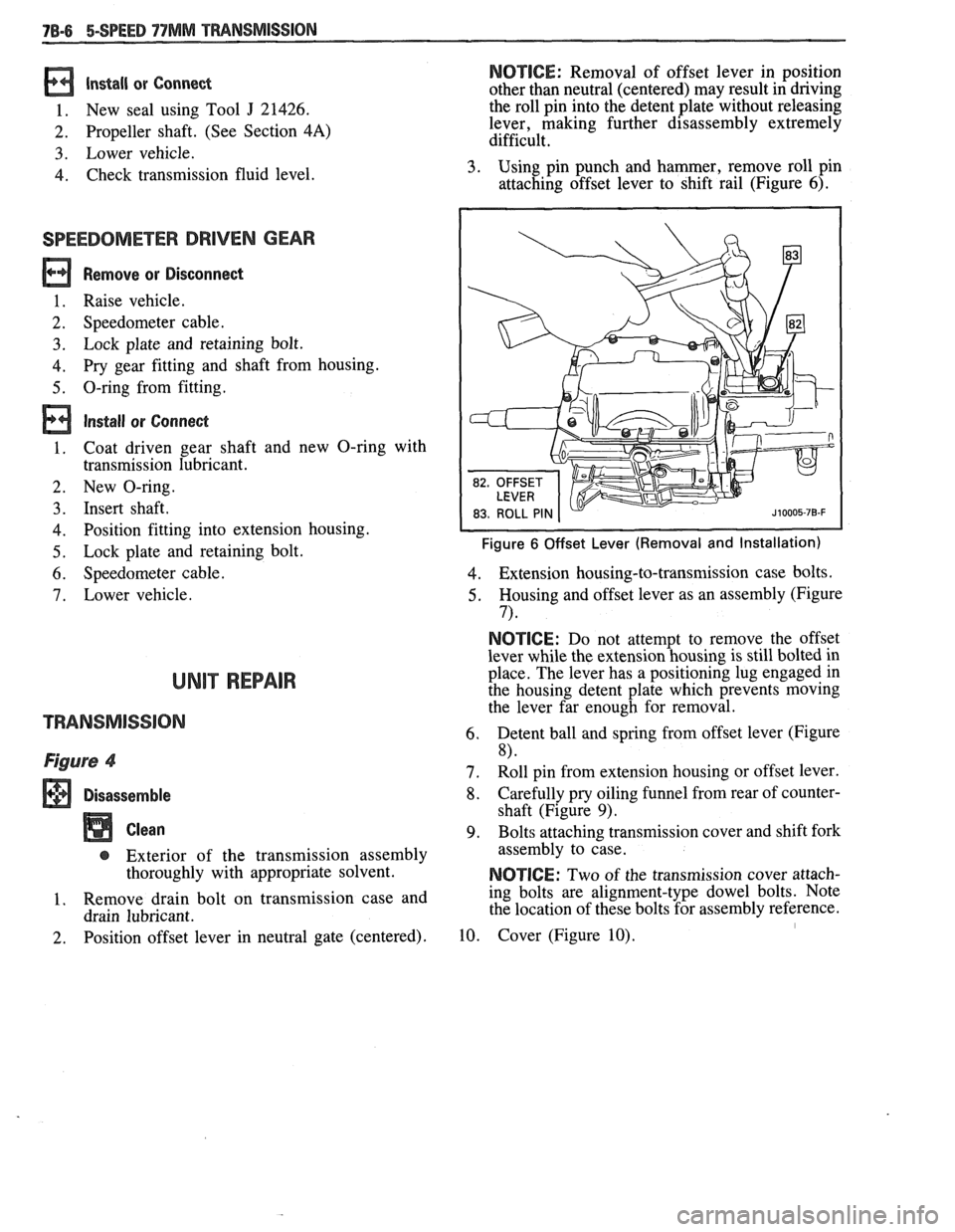
3. Using pin punch and hammer, remove roll pin
attaching offset lever to shift rail (Figure
6).
Figure 6 Offset Lever (Removal and Installation)
4. Extension housing-to-transmission case bolts.
5. Housing and offset lever as an assembly (Figure
7) *
NOTICE: Do not attempt to remove the offset
lever while the extension housing is still bolted in
place. The lever has a positioning lug engaged in
the housing detent plate which prevents moving
the lever far enough for removal.
6. Detent ball and spring from offset lever (Figure
8)
7. Roll pin from extension housing or offset lever.
8. Carefully pry oiling funnel from rear of counter-
shaft (Figure
9).
9. Bolts attaching transmission cover and shift fork
assembly to case.
NOTICE: Two of the transmission cover attach-
ing bolts are alignment-type dowel bolts. Note
the location of these bolts for assembly reference.
10. Cover (Figure 10). I
Page 1155 of 1825
78-18 5-SPEED 77MM TRANSMISSION
Blocker ring and fifth gear synchronizer in fifth
gear shift fork. Slide fork rail assembly and syn-
chronizer into position. (Figure 20)
Fifth gear synchronizer retainer and snap ring
(Figure 12).
Oiling funnel into rear of countershaft (Figure
9)
Position fifthlreverse shift lever in case.
Connect lever return spring to front of case.
Make sure reverse shift fork pin and fifth gear
shift rail pin are engaged with shift lever and
install fifth
gearlreverse lever, pivot bolt and
retaining clip. Coat pivot bolt threads with pipe
thread sealant
#lo52080 or equivalent.
Reverse lamp switch. Coat threads with pipe
thread sealant
# 1052080 or equivalent.
Speedometer gear and retaining clip.
Circlip.
Apply 3mm
(118in.) bead of RTV Sealant,
# 105275 1 or equivalent, to transmission cover
assembly.
Make sure all synchronizers are in the neutral
position and that the shift forks in the cover are
in the neutral (center) position. Lower cover
onto case while aligning shift forks and synchro-
nizer sleeves.
Center cover and install two dowel bolts.
Remaining cover bolts.
Tighten
@ Torque all cover bolts to 14 N*m (10 lbs.
ft.).
Apply 3mm (118 in.) bead of RTV Sealant,
#I05275 1 or equivalent, to extension housing
mating surface.
Coat detent spring with petroleum jelly and
insert in offset lever. Lubricate detent plate and
install detent ball in neutral position on plate.
Position offset lever in extension housing with
spring over detent ball. Slide lever and exten-
sion housing into position as an assembly.
Extension housing vent.
Press downward on offset lever to compress
detent spring and push lever and housing into
position.
Extension housing bolts. Apply pipe thread
sealant
#lo52080 or equivalent to threads of
top two bolts.
Tighten
@ Torque extension housing bolts to 30 Nm
(23 lbs. ft.)
Align and install roll pin in offset lever and shift
rail. 35. Damper
sleeve in offset lever.
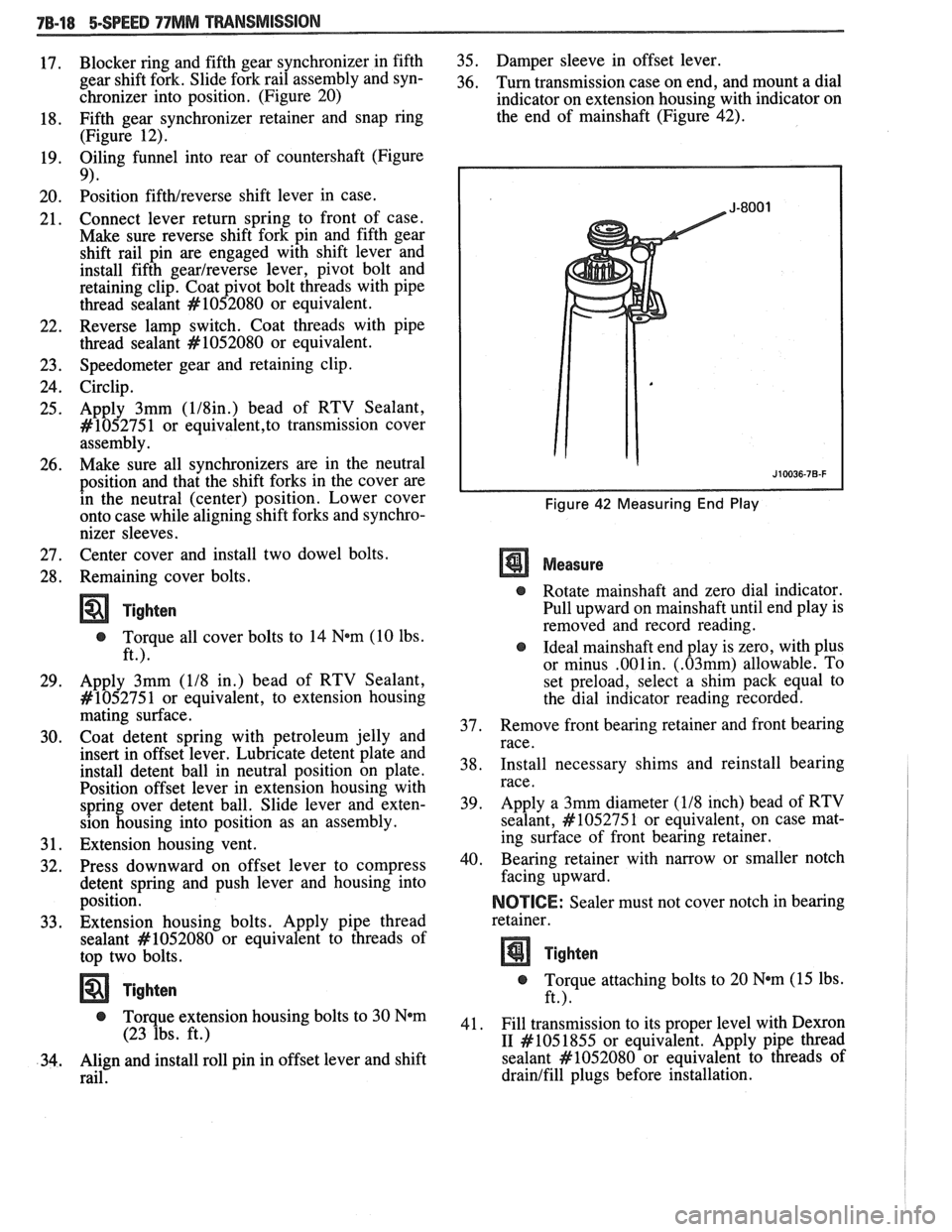
36. Turn transmission case on end, and mount a dial
indicator on extension housing with indicator on
the end of mainshaft (Figure 42).
Figure 42 Measuring End Play
Measure
@ Rotate mainshaft and zero dial indicator.
Pull upward on mainshaft until end play is
removed and record reading.
@ Ideal mainshaft end play is zero, with plus
or minus
.001in. (.03mm) allowable. To
set preload, select a shim pack equal to
the dial indicator reading recorded.
37. Remove
front bearing retainer and front bearing
race.
38. Install
necessary shims and reinstall bearing
race.
39. Apply
a 3mm diameter
(118 inch) bead of RTV
sealant,
#lo5275 1 or equivalent, on case mat-
ing surface of front bearing retainer.
40. Bearing retainer with narrow
or smaller notch
facing upward.
NOICE: Sealer must not cover notch in bearing
retainer.
Tighten
@ Torque attaching bolts to 20 N*m (15 lbs.
ft.).
41. Fill transmission to its proper level with
Dexron
I1 #I05 1855
or equivalent. Apply pipe thread
sealant
#lo52080 or equivalent to threads of
drainlfill plugs before installation.
Page 1720 of 1825
1. PLASTIC NAIL
2. WATER DEFLECTOR
DOORS - F STYLE 5H-7
is made up of a door side and body side strap with a
removable hinge pin. The removable hinge pin has
a
barrel type retaining clip and a serrated shank near the
head which provides a friction fit with the mating
surface on the hinge. All service hinge straps have holes
to permit bolt-on installation. Tapped anchor plates
must be used instead of nuts and washers to insure
structural integrity when replacing a door side hinge
strap assembly. No service welding is required when
replacing door hinge straps. The door lower hinge has
an integral two stage hold-open feature. Door side and
body side hinge straps, hinge pins, tapped anchor
plates, hinge bolts and bushings are available as
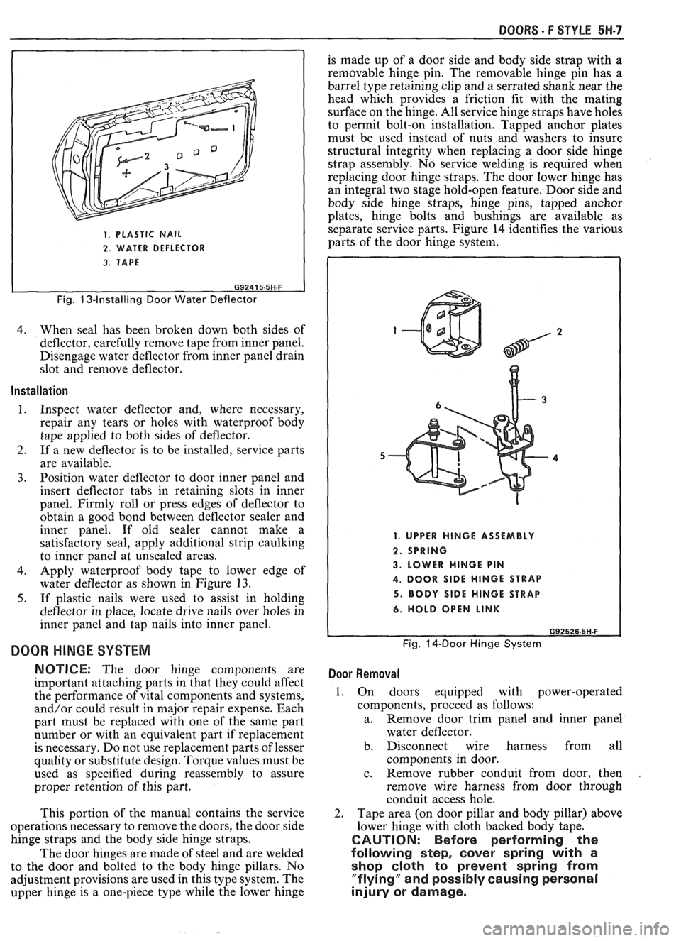
separate service parts. Figure 14 identifies the various
parts of the door hinge system.
3. TAPE
I
Fig. 13-Installing Door Water Deflector
4. When seal has been broken down both sides of
deflector, carefully remove tape from inner panel.
Disengage water deflector from inner panel drain
slot and remove deflector.
Installation
1. Inspect water deflector and, where necessary,
repair any tears or holes with waterproof body
tape applied to both sides of deflector.
2. If a new deflector is to be installed, service parts
are available.
3. Position water deflector to door inner panel and
insert deflector tabs in retaining slots in inner
panel. Firmly roll or press edges of deflector to
obtain a good bond between deflector sealer and
inner panel. If old sealer cannot make a
satisfactory seal, apply additional strip caulking
to inner panel at unsealed areas.
4. Apply waterproof body tape to lower edge of
water deflector as shown in Figure
13.
5. If plastic nails were used to assist in holding
deflector in place, locate drive nails over holes in
inner panel and tap nails into inner panel.
DOOR HINGE SYSTEM
NOTICE: The door hinge components are
important attaching parts in that they could affect
the performance of vital components and systems,
and/or could result in major repair expense. Each
part must be replaced with one of the same part
number or with an equivalent part if replacement
is necessary. Do not use replacement parts of lesser
quality or substitute design. Torque values must be
used as specified during reassembly to assure
proper retention of this part.
This portion of the manual contains the service
operations necessary to remove the doors, the door side
hinge straps and the body side hinge straps.
The door hinges are made of steel and are welded
to the door and bolted to the body hinge pillars. No
adjustment provisions are used in this type system. The
upper hinge is a one-piece type while the lower hinge
1. UPPER HINGE ASSEMBLY
2. SPRING
3. LOWER HINGE PIN
4. DOOR SlDE HINGE STRAP
5. BODY SlDE HINGE STRAP
6. HOLD OPEN LINK
Fig. 14-Door Hinge System
Door Removal
1. On doors equipped with power-operated
components, proceed as follows:
a. Remove
door trim panel and inner panel
water deflector.
b. Disconnect wire harness from all
components in door.
c. Remove rubber conduit from door, then
.
remove wire harness from door through
conduit access hole.
2. Tape area (on door pillar and body pillar) above
lower hinge with cloth backed body tape.
CAUTION: Before performing the
following step,
cover spring with a
shop cloth to prevent spring from
"flying" and possibly causing personal
injury or damage.
Page 1749 of 1825
7H-6 REAR END - F STYLE
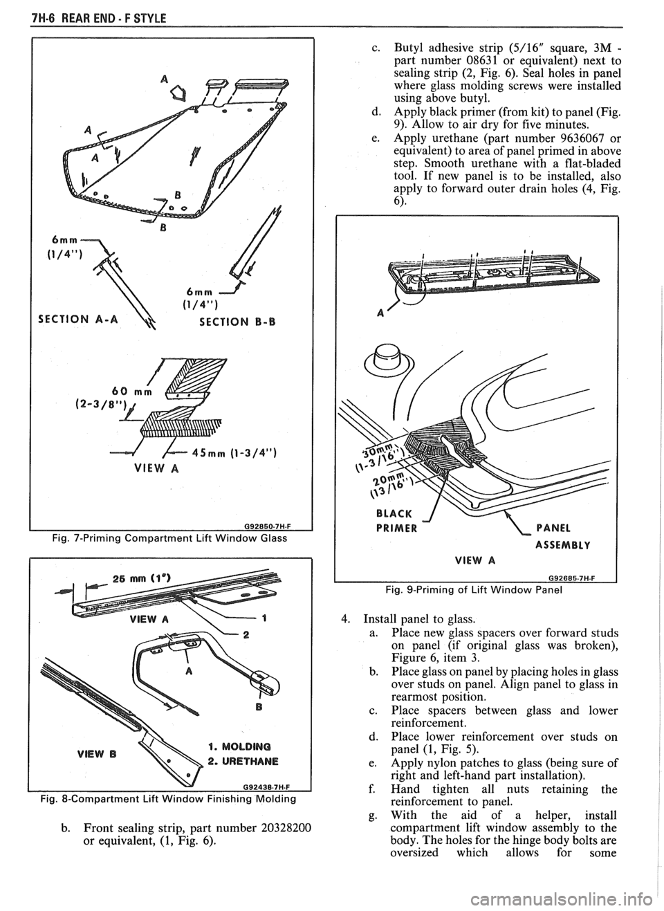
SECTION A-A SECTION B-B
G92850-7H-F
Fig. 7-Priming Compartment Lift Window Glass
1. MOLDING
2. URETHANE
c.
Butyl adhesive strip (5/16" square, 3M -
part number 08631 or equivalent) next to
sealing strip
(2, Fig. 6). Seal holes in panel
where glass molding screws were installed
using above butyl.
d. Apply black primer (from kit) to panel (Fig.
9). Allow to air dry for five minutes.
e. Apply urethane (part number 9636067 or
equivalent) to area of panel primed in above
step. Smooth urethane with a flat-bladed
tool. If new panel is to be installed, also
apply to forward outer drain holes (4, Fig.
6).
ASSEMBLY
VIEW A
Fig. 9-Priming of Lift Window Panel
4. Install panel to glass.
a. Place new glass spacers over forward studs
on panel (if original glass was broken),
Figure 6, item
3.
b.
Place glass on panel by placing holes in glass
over studs on panel. Align panel to glass in
rearmost position.
c. Place spacers between glass and lower
reinforcement.
d. Place lower reinforcement over studs on
panel
(1, Fig. 5).
e. Apply nylon patches to glass (being sure of
right and left-hand part installation).
f. Hand tighten all nuts retaining the
Fig. 8-Compartment Lift Window Finishing Molding reinforcement to panel.
g. With the aid of a helper, install
b. Front sealing strip, part number 20328200 compartment
lift window assembly to the
or equivalent, (1, Fig. 6). body.
The holes for the hinge body bolts are
oversized which allows for some