Page 1639 of 1825

8E -12 WINDSHIELD WIPER SYSTEMS. F CAWLINE
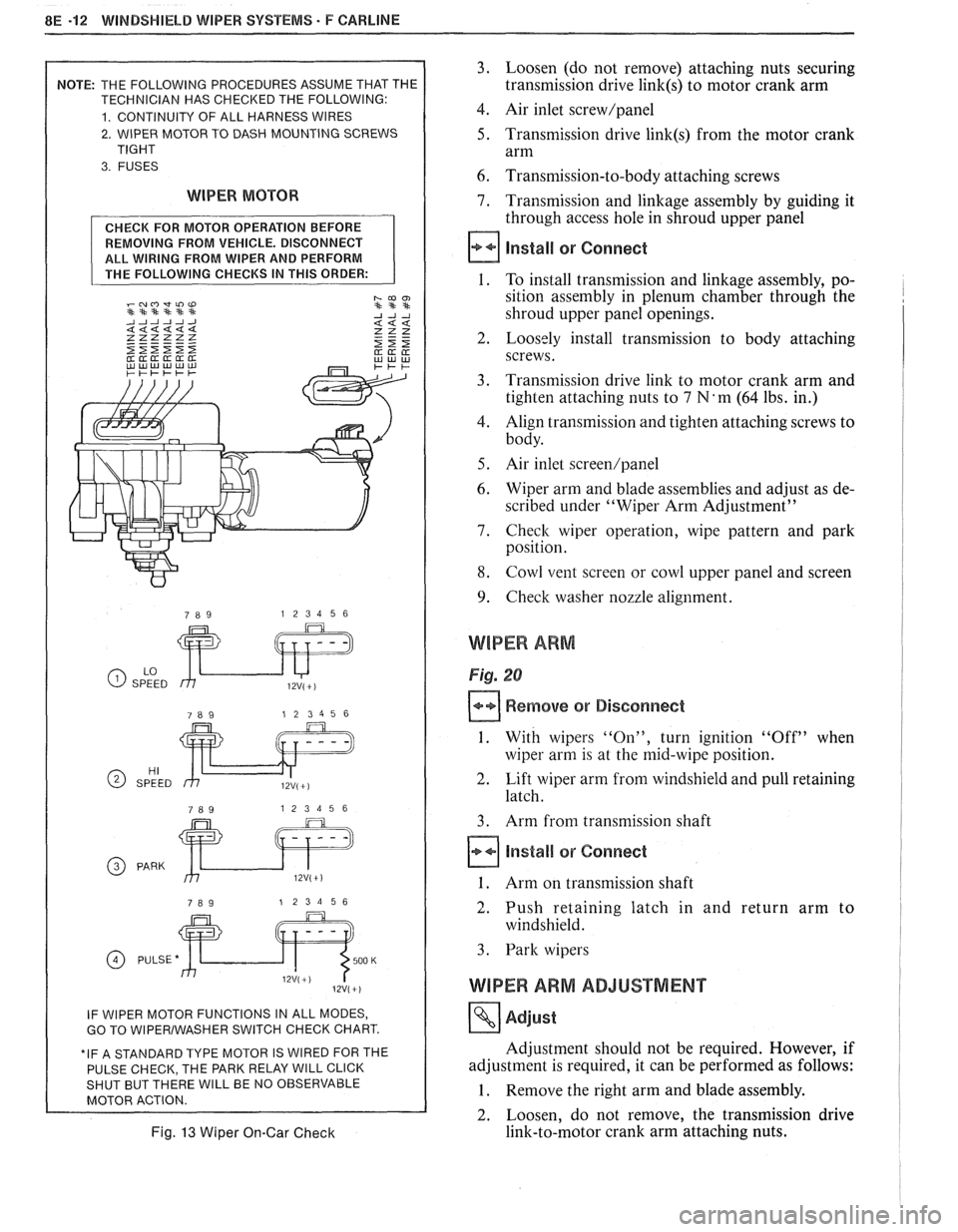
2. WIPER MOTOR TO DASH MOUNTING SCREWS
WIPER MOTOR
REMOVING FROM VEHICLE. DISCONNECT
ALL WIRING FROM WIPER AND PERFORM
GO TO WlPERlWASHER SWITCH CHECK CHART.
E PARK RELAY
WlLL CLICK WlLL BE NO OBSERVABLE
Fig. 13 Wiper On-Gar Check
3. Loosen (do not remove) attaching nuts securing
transmission drive
link(s) to motor crank arm
4. Air inlet screw/panel
5. Transmission drive link(s) from the motor crank
arm
6. Transmission-to-body attaching screws
7. Transmission and linkage assembly by guiding it
through access hole in shroud upper panel
install or Connect
1. To install transmission and linkage assembly, po-
sition assembly in plenum chamber through the
shroud upper panel openings.
2. Loosely install transmission to body attaching
screws.
3. Transmission drive link to motor crank arm and
tighten attaching nuts to
7 N'm (64 lbs. in.)
4. Align transmission and tighten attaching screws to
body.
5. Air inlet screen/panel
6. Wiper arm and blade assemblies and adjust as de-
scribed under "Wiper Arm Adjustment"
7. Check wiper operation, wipe pattern and park
position.
8. Cowl vent screen or cowl upper panel and screen
9. Check washer nozzle alignment.
WIPER ARM
Fig. 20
Remove or Disconnect
1. With wipers "On", turn ignition "Off" when
wiper arm is at the mid-wipe position.
2. Lift wiper arm from windshield and pull retaining
latch.
3. Arm from transmission shaft
Install or Connect
1. Arm on transmission shaft
2. Push retaining latch in and return arm to
windshield.
3. Park wipers
WIPER ARM ADJUSTMENT
Adjust
Adjustment should not be required. However, if
adjustment is required, it can be performed as follows:
1. Remove the right arm and blade assembly.
2. Loosen, do not remove, the transmission drive
link-to-motor crank arm attaching nuts.
Page 1640 of 1825

WINDSHIELD WIPER SYSTEMS - F CARLINE 8E -13
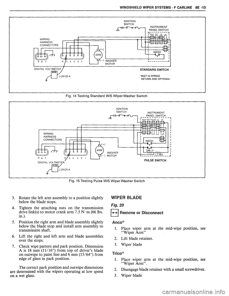
'MIST IS SPRING
RETURN AND OPTIONAL
Fig. 14 Testing Standard WIS Wiper-Washer Switch
Fig.
15 Testing Pulse WIS Wiper-Washer Switch
3. Rotate the left arm assembly to a position slightly
below the blade stops.
4. Tighten the attaching nuts on the transmission
drive
link(s) to motor crank arm 7.5 N'm (66 lbs.
in.).
5. Position the right arm and blade assembly slightly
below the blade stop and install arm assembly to
transmission shaft.
6. Lift the right and left arm and blade assemblies
over the stops.
7. Check wipe pattern and park position. Dimension
A is 18 mm (1 1/16") from top of driver's blade
on
outwipe to paint line and 6 mm (15/64") from
edge of glass in park position.
The correct park position and
outwipe dimensions
are determined with the wipers operating at low speed
on a wet glass.
WIPER BLADE
Fig. 20
Remove or Disconnect
Anso@
1. Place wiper arm at the mid-wipe position, see
"Wiper Arm"
2. Lift blade retainer.
3. Wiper blade
TY~GO@
1. Place wiper arm at the mid-wipe position, see
"Wiper Arm".
2. Disengage blade retainer with a small screwdriver.
3. Wiper blade
Page 1641 of 1825
8E -14 WINDSHIELD WIPER SYSTEMS - F CARLINE
Fig. 16 Wiper-Washer Switch Check Chart
CHECK FOR WASHER PUMP OPERATION BEFORE
REMOVING FROM VEHICLE. REMOVE COVER
HARNESS CONNECTOR AND APPLY
12V(+) TO #4 TERMINAL OF WIRING HARNESS, GROUND #5 TERMINAL AS SHOWN.
WIRING HARNESS
CONNECTOR WASHER
MOTOR
B(+) ON TERMINAL #4 -~mwli)w **st***
Fig. 17 Washer Pump On-Car Check
Install or Connect
AncoB and Tricoa
1. Wiper blade onto wiper arm
2. Park wipers.
WIPER BLADE INSERT
Fig. 20
Remove or Disconnect
Ancoa
1. Place wiper arm at the mid-wipe position, see
"Wiper Arm".
2. Push down on insert retainer.
3. Insert with retainer
TricoB
I. Place wiper arm at the mid-wipe position, see
"Wiper Arm".
2. Squeeze insert retainer together.
3. Insert