1988 PONTIAC FIERO steering wheel
[x] Cancel search: steering wheelPage 1162 of 1825
CLUTCH 7C-5
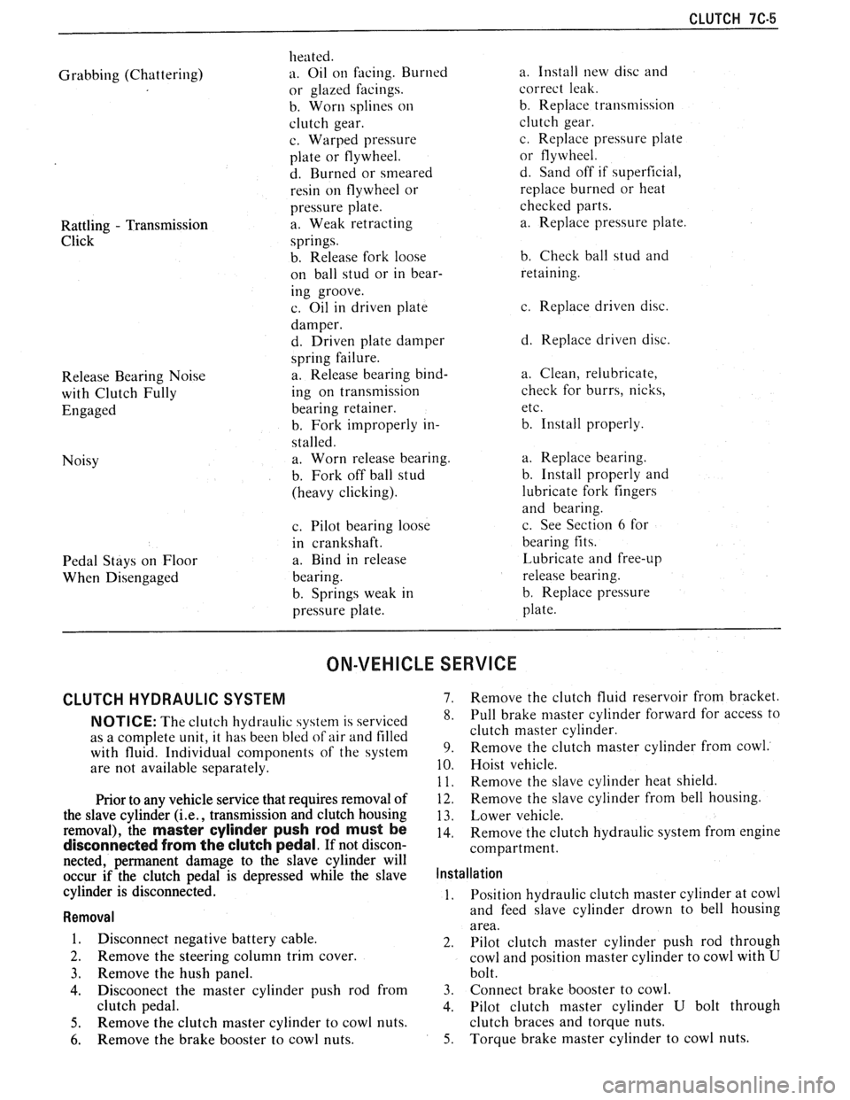
Grabbing (Chattering)
Rattling
- Transmission
Click
Release Bearing Noise
with Clutch Fully
Engaged
Noisy
Pedal Stays on Floor
When Disengaged heated.
a. Oil
on facing. Burned
or glazed facings.
b. Worn splines
on
clutch gear.
c. Warped pressure
plate or flywheel.
d. Burned or smeared
resin on flywheel or
pressure plate.
a. Weak retracting
springs.
b. Release fork loose
on ball stud or in bear-
ing groove.
c. Oil in driven plate
damper.
d. Driven plate damper
spring failure.
a. Release bearing bind-
ing on transmission
bearing retainer.
b. Fork improperly in-
stalled. a. Worn release bearing.
b. Fork off ball stud
(heavy clicking).
c. Pilot bearing loose
in crankshaft.
a. Bind in release
bearing.
b. Springs weak in
pressure plate. a.
Install new disc and
correct leak.
b. Replace transmission
clutch gear.
c. Replace pressure plate
or flywheel.
d. Sand off if superficial,
replace burned or heat
checked parts.
a. Replace pressure plate.
b. Check ball stud and
retaining.
c. Replace driven disc.
d. Replace driven disc.
a. Clean, relubricate,
check for burrs, nicks,
etc.
b. Install properly.
a. Replace bearing.
b. Install properly and
lubricate fork fingers
and bearing.
c. See Section
6 for
bearing fits.
Lubricate and free-up
release bearing.
b. Replace pressure
plate.
ON-VEHICLE SERVICE
CLUTCH HYDRAULIC SYSTEM 7. Remove the clutch fluid reservoir from bracket.
NOTICE: The clutch hydraul~c 4ystern is serviced 8. Pull brake niaster cylinder forward for access to
as a complete unit, it has been bled
of air and filled clutch master cylinder.
with fluid. Individual components of the system 9. Remove the clutch master cylinder from cowl.
are
not available separately. 10. Hoist vehicle.
1 1. Remove the slave cvlinder heat shield.
Prior to any vehicle service that requires removal of
the slave cylinder
(i.e., transmission and clutch housing
removal), the
master cylinder push rod must be
disconnected from the clutch pedal. If not discon-
nected, permanent damage to the slave cylinder will
occur if the clutch pedal is depressed while the slave
cylinder is disconnected.
Removal
1. Disconnect negative battery cable.
2. Remove the steering column trim cover.
3. Remove the hush panel.
4. Discoonect the master cylinder push rod from
clutch pedal.
5. Remove the clutch master cylinder to cowl nuts.
6. Remove the brake booster to cowl nuts.
12. Remove the slave cylinder from bell housing.
13. Lower vehicle.
14. Remove the clutch hydraulic system from engine
compartment.
Installation
1. Position
hydraulic clutch master cylinder at cowl
and feed slave cylinder drown to bell housing
area.
2. Pilot clutch master cylinder push rod through
cowl and position master cylinder to cowl with
U
bolt.
3. Connect brake booster to cowl.
4. Pilot clutch master cylinder
U bolt through
clutch braces and torque nuts.
5. Torque brake master cylinder to cowl nuts.
Page 1163 of 1825
7C-6 CLUTCH
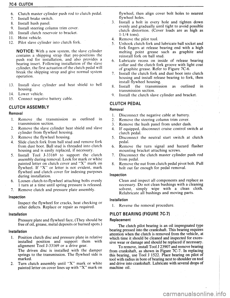
6. Clutch master cylinder push rod to clutch pedal.
7. Install brake switch.
8. Install hush panel.
9. Install steering column trim cover.
10. Install clutch reservoir to bracket.
1 1. Hoist vehicle.
12. Pilot slave cylinder into clutch fork.
NOTICE: With a new system, the slave cylinder
contains a shipping strap that pre-positions the
push rod for installation, and also provides a
bearing insert.
Follojving installation of the slave
cylinder, the first actuation of the clutch pedal will
break the shipping strap and give
normal system
operation.
13. Install slave cylinder and heat shield to bell
housing.
14.
Lojver vehicle.
15. Connect negative battery cable.
CLUTCH ASSEMBLY
Removal
1. Remove the transmission as outlined in
transmission section.
2. Remove the slave cylinder heat shield and slave
cylinder
from flywheel housing.
3. Reniove the flywheel housing.
4. Slide clutch fork from ball stud and remove fork
from dust boot. Ball stud is threaded into clutch
housing and is easily replaced, if necessary.
5. Install Tool 5-33169 to support the clutch
assen~bly during removal. Look for mark or white
painted letter on clutch cover and
"X" mark on
flywheel. If
"Xu or letter is not evident, mark
flywheel and clutch cover for indexing purposes
during installation.
6. Loosen clutch-to-flywheel attaching bolts evenly
1 turn at a time until spring pressure is released.
7. Remove clutch and pressure plate assembly.
lnspection
Inspect the flywheel for cracks, heat checking or
other defects. Replace or repair as required.
Installation
Pressure plate and flywheel face, (They should be
free of oil, grease, metal deposits or burned spots.)
Installation
1. Position clutch disc and pressure plate in relative
installed position and support them with
alignment Tool J-33169 or a drive gear.
The driven disc is installed with the damper
springs to the transmission. The flywheel side is
marked.
2. Turn clutch assembly until "X" mark or white
painted letter on cover lines up with
"X" mark on flywheel,
then align cover bolt holes to nearest
flywheel holes.
3. Install a bolt in every hole and tighten down
evenly and gradually until tight to avoid possible
clutch distortion. (Cover loads are as high as
1- 1/4 tons).
4. Remove the pilot tool.
5. Unhook clutch fork and lubricate ball socket and
fork fingers at release bearing end with a high
melting point grease such as graphite and
reinstall fork on ball stud.
6. Lubricate recess on inside of release bearing
collar and the clutch fork groove with light coat
of graphite grease. Refer to Figure 7C-6.
7. Install the clutch fork and dust boot into clutch
housing and install release bearing to fork, then
install flywheel housing.
8. Install the transmission as outlined in
transmission section.
9. Install the clutch slave cylinder and bracket.
CLUTCH PEDAL
Removal
Disconnect the negative cable at battery.
Remove the steering column trim cover.
Remove the hush panel from under dash.
If equipped, disconnect cruise control switch at
clutch pedal.
Disconnect the neutral start switch at clutch
pedal.
Renlove the turn signal and hazard flasher
mounting bracket attaching screws.
Disconnect the clutch master cylinder push rod
from pedal.
Remove the nut from clutch pedal pivot bolt. Pull
bolt out far enough for pedal removal.
Inspection
Clean and inspect all components and replace as
necessary. Do not clean bushings with a cleaning
solvent, simply wipe with a clean cloth.
Relubricate all bushings and moving parts.
Installation
1. Reverse the removal procedure.
PILOT BEARING (FIGURE 7C-7)
Replacement
The clutch pilot bearing is an oil impregnated type
bearing pressed into the crankshaft. This bearing requires
attention when the clutch is removed from the vehicle, at
which time it should be cleaned and inspected for exces-
sive wear or damage and should be replaced if necessary.
To remove, install Tool
J 23907 and remove bearing
from crankshaft, as shown in Figure
7C-7. In replacing
this bearing, use Tool
J 1522. Place bearing on pilot of
tool with radius in bore of bearing next to shoulder on tool
and drive into crankshaft. Lubricate with several drops of
machine oil.
Page 1171 of 1825
INTRODUCTION
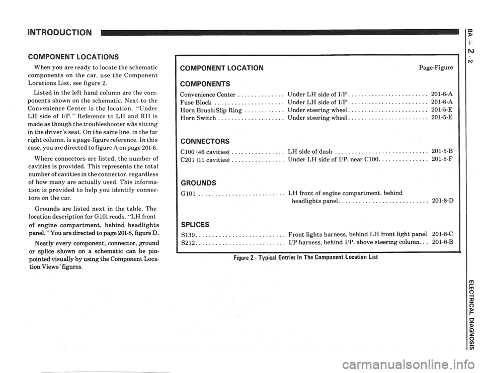
COMPONENT LOCATIONS
When you are ready to locate the schematic
components on the car, use the Component
Locations List, see figure 2.
Listed in the left hand column are the com-
ponents shown on the schematic. Next to the
Convenience Center is the location, "Under
LH side of
I/P." Reference to LH and RH is
made as though the troubleshooter
was sitting
in the driver's seat. On the same line, in the far
right column, is a page-figure reference. In this
case, you are directed to figure
A on page 201-6.
Where connectors are listed, the number of
cavities is provided. This represents the total
number of cavities in the connector, regardless
of how many are actually used. This informa-
tion is provided to help you identify connec-
tors on the car.
Grounds are listed next in the table. The
location description for
GlOl reads, "LH front
of engine compartment, behind headlights
panel. "You are directed to page 201-8, figure D.
Nearly every component, connector, ground
or splice shown on a schematic can be pin-
pointed visually by using the Component Loca-
tion Views' figures.
COMPONENT LOCATION Page-Figure
COMPONENTS
........................ Convenience Center .............. Under LH side of IIP 201-6-A
..................... ........................ Fuse Block Under LH side of IIP 201-6-A
....................... Horn BrushISlip Ring ............ Under steering wheel. 201-5-E
....................... Horn
Switch .................... Under steering wheel. 201-5-E
CONNECTORS
............................ ................ ClOO (46 cavities)
LH side of dash 201-5-B
................ .............. C201 (11 cavities) Under
LH side of IIP, near C100. 201-5-F
GROUNDS
.......................... GlOl LH front of engine compartment, behind
.......................... headlights panel. 201-8-D
SPLICES
.......................... S139. Front lights harness, behind LH front light panel 201-8-C
.......................... S212. IIP harness, behind IIP, above steering column. .. 201-6-B
Figure 2 - Typical Entries In The Component Location List
Page 1330 of 1825
HORNS
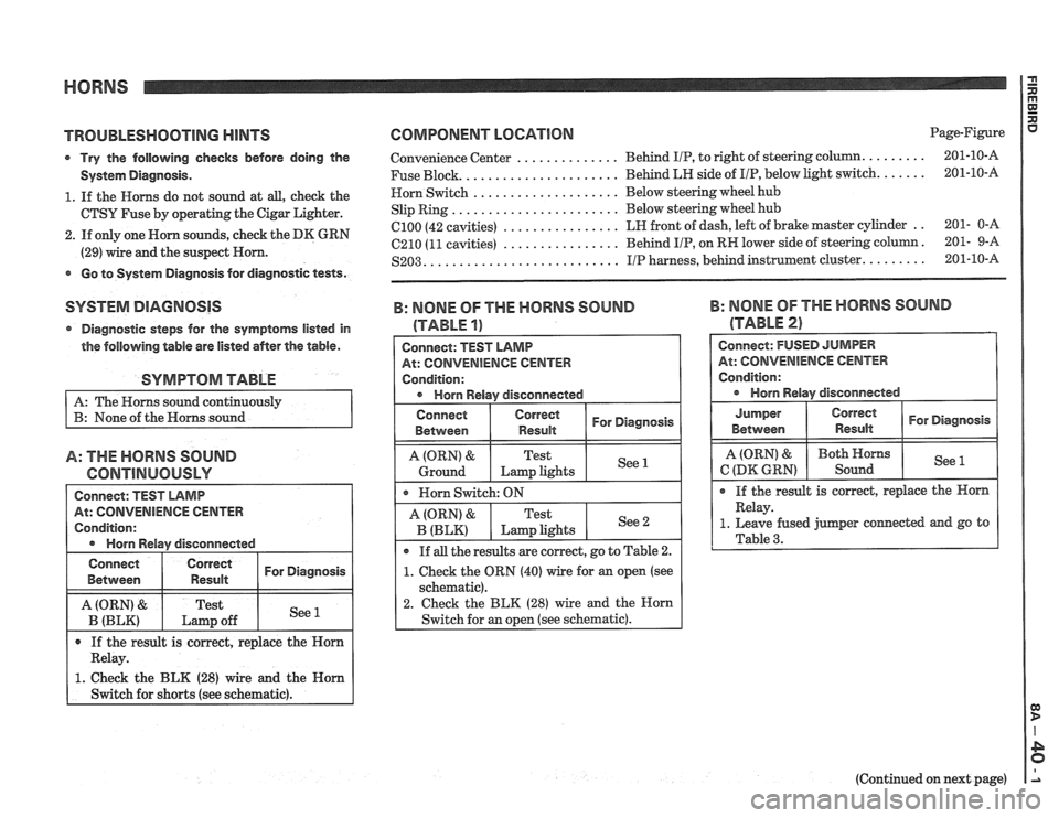
TROUBEESHOOTlNG HINTS
Try the following checks before doing the
System Diagnosis.
1. If the Horns do not sound at all, check the
CTSY Fuse by operating the Cigar Lighter.
2. If only one Worn sounds, check the DK GRN
(29) wire and the suspect Horn.
Go to System Diagnosis for diagnostic tests.
SYSTEM DIAGNOSIS
Diagnostic steps for the symptoms listed in
the following table are listed after the table.
SYMPTOM TABLE
A: The Horns sound continuously
B: None of the Horns sound
A: THE HORNS SOUND
GONTlNUOUSLY
COMPONENT LOCATION Page-Figure
.............. Convenience Center Behind IIP, to
right of steering column. ........ 201-10-A
..................... ...... Fuse Block. Behind LH side
of I/P, belour light switch. 201-10-A
.................... Horn Switch Below
steering wheel hub
....................... Slip Ring Below
steering wheel hub
................ el00 (42 cavities) LH front of dash, left of brake master cylinder .. 201- 0-A
................ C210 (11 cavities) Behind IIP, on
RW lower side of steering column. 201- 9-A
.......................... S203. IIP harness, behind instrument cluster. ........ 201-10-8
B: NONE OF THE MORNS SOUND
(TABLE a,
Connect: TEST LAMB
IiENcE CENTER
I Condition:
a Horn Relay disconnected
Connect
Between I ","d::r I For Diagnosis
A (ORN) &
Ground
B: NOME OF THE HORNS SOUND
(TABLE 21
Horn Switch: ON
Jumper
Between
Test
Lamp lights
(Continued on next page)
See 1
See 2 A (ORN) &
B (BLK)
If all the results
are correct, go to Table 2.
1. Cheek the ORN (40) wire for an open (see
schematic).
2. Check the BLK (28) wire and the Horn
Switch for an open (see schematic).
Test
Lmp lights
Page 1550 of 1825
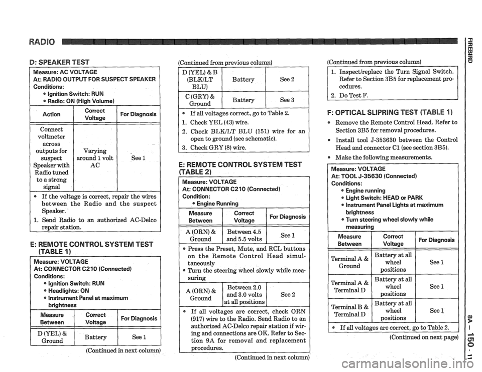
D: SPEAKER TEST (Continued from previous column)
At: RADIO OUTPUT FOR SUSPECT SPEAKER
Ignition Switch: RUN
o an authorized AC-Delco
E: REMOTE CONTROL SYSTEM TEST
(TABLE
1)
Measure: VOLTAGE
At: CONNECTOR C210 (Connected)
Conditions: Ignition Switch: RUN
. Headlights: ON
I r Instrument Panel at maximum I brightness
I Measure I I For Diagnosis ( Between
I & I Battery I See 1 1 Ground I I I I
(Continued in next column)
D (YEL) & B
(BLKILT Battery See 2
BLU)
(GRY) & Battery
Ground See 3
If all voltages correct, go to Table
2.
1. Check YEL (43) wire.
2. Check BLKILT BLU (151) wire for an
open to ground (see schematic).
3. Check GRY
(8) wire.
E: REMOTE CONTROL SYSTEM TEST
(TABLE 2)
At: CONNECTOR 6210 (Connected)
Condition:
Measure
Between
I tz I For Diagnosis
1 I - I
A (ORN) & Between 4.5
Ground and 5.5 volts See 1
Press
the Preset, Mute, and RCL buttons
on the Remote Control
Head simul-
taneously
r Turn the steering wheel slowly while mea-
Between 2.0
at
all positions
If
all voltages are correct, check ORN
(917) wire to the Radio. Send Radio to an
authorized AC-Delco repair station if wir-
ing and connections are OK. Refer to Sec-
tion
9A for removal and replacement
~rocedures. ---- - -
(Continued in next column) (Continued from
previous
column)
Refer to Section 3B5 for replacement pro-
cedures.
2. DoTest F.
F: OPTlCAL SLlPRlNG TEST (TABLE 1 )
e Remove the Remote Control Head. Refer to
Section 3B5 for removal procedures.
r Install tool 5-353630 between the Control
Head and connector
C1 (see section 3B5).
Make the following measurements.
At: TOOL 5-35630 (Connected)
Engine running
0 Light Switch: MEAD or PARK
0 lnstrument Panel Lights at maximum
@ If all voltages are correct, go to Table 2.
(Continued on next page)
Page 1551 of 1825
RADIO
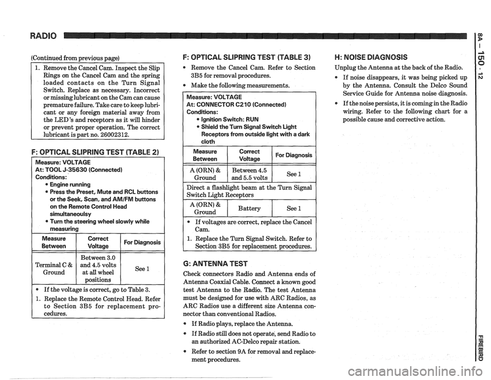
(Continued from previous page)
1. Remove the Cancel Cam. Inspect the Slip
Rings on the Cancel Cam and the spring
loaded contacts on the Turn Signal
Switch. Replace as necessary. Incorrect
or missinglubricant on the Cam can cause
premature failure. Take care to keep lubri-
cant or any foreign material away from
the
LED'S and receptors as it will hinder
or prevent proper operation. The correct
lubricant is part no.
26002312.
F: OPTICAL SLlPRlNG TEST (TABLE 2)
Measure: VOLTAGE
At: TOOL J-35630 (Connected)
Conditions:
@ Engine running
0 Press the Preset, Mute and RCL buttons
or the Seek, Scan, and
AMIFM buttons
on the Remote Control Head
sirnultaneoulsy
0 Turn the steering wheel slowly while
measuring
Measure
Correct I For Diagnosis I
I I Between 3.0 1 I Terminal C & and 4.5 volts
1 Ground 1 at all wheel
I 1 positions I I
I . If the voltage is correct, go to Table 3. (
1. Replace the Remote Control Head. Refer
to Section
3B5 for replacement pro-
cedures.
F: OPTICAL SLlPRllUG TEST (TABLE 3) H: NOlSE DIAGNOSIS
Remove the Cancel Cam. Refer to Section Unplug
the Antenna at the back of the Radio.
3B5 for removal procedures.
If noise disappears, it was being picked up
0 Make the following measurements.
by the Antenna. Consult the Delco Sound
Service Guide for Antenna noise diagnosis.
If the noise persists, it is coming in the Radio
wiring. Refer to the following chart for a
possible cause and corrective action.
At: CONNECTOR 6210 (Connected)
@ Ignition Switch: RUN
Shield the Turn Signal Switch Light
Receptors from outside light with a dark
1. Replace the Turn Signal Switch. Refer to
6: ANTENNA TEST
Check connectors Radio and Antenna ends of
Antenna Coaxial Cable. Connect a known good
test Antenna to the Radio. The test Antenna
must be designed for use
with ARC Radios, as
ARC Radios use a different size Antenna con-
nector than conventional Radios.
@ If Radio plays, replace the Antenna.
If Radio still does not operate, send Radio to
an authorized AC-Delco repair station.
Refer to section 9A for removal and replace-
ment procedures.
Page 1556 of 1825
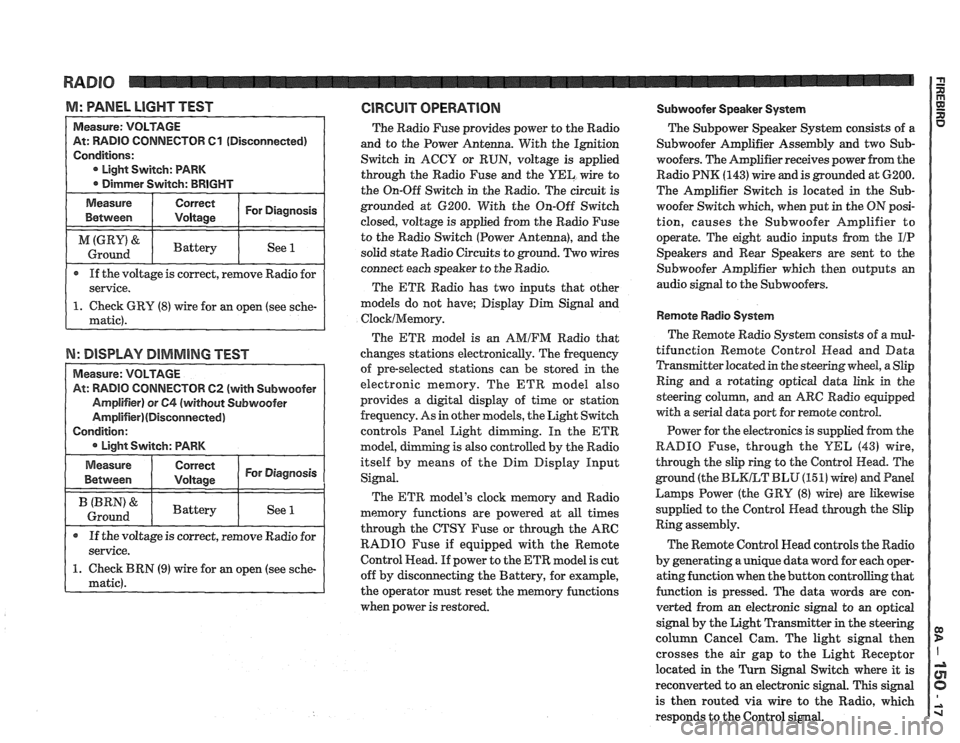
M: WNEL LIGHT TEST GlRGUlT OPERATION Subwoofer Speaker System
TOR 61 (Disconnected)
If the voltage is correct, remove Radio for
N: DISPLAY DIMMING TEST
TOW 62 (with Subwoofer
The Radio Fuse provides power to the Radio
and to the Power Antenna. With the Ignition
Switch in ACCY or RUN, voltage is applied
through the Radio Fuse and the
UEL wire to
the On-Off Switch in the Radio. The circuit is
grounded at 6200. With the On-Off Switch
closed, voltage is applied from the Radio Fuse
to the Radio Switch (Power Antenna), and the
solid state Radio Circuits to ground. Two wires
connect each speaker to the Radio.
The ETR Radio has two inputs that other
models do not have; Display Dim Signal and
ClocklMemory.
The ETR model is an AMIFM Radio that
changes stations electronically. The frequency
of pre-selected stations can be stored
in the
electronic memory. The ETR model also
provides a digital display of time or station
frequency. As in other models, the Light Switch
controls Panel Light dimming. In the
ETR
model, g is also controlled by the Radio
itself by means of the Dim Display Input
Signal.
The ETR model's clock memory and Radio
memory functions are powered at all times
through the CTSY Fuse or through the ARC
RADIO Fuse if equipped with the Remote
Control Head. If power to the ETR model is cut
off by disconnecting the Battery, for example,
the operator must reset the memory functions
when power is restored. The
Subpower Speaker
System consists of a
Subwoofer Amplifier Assembly and two Sub-
woofers. The Amplifier receives power from the
Radio PNK
(143) wire and is grounded at 6200.
The Amplifier Switch is located in the
Sub-
woofer Switch which, when put in the ON posi-
tion, causes the Subwoofer Amplifier to
operate. The eight audio inputs from the
I/P
Speakers and Rear Speakers are sent to the
Subwoofer Amplifier which then outputs an
audio signal to the Subwoofers.
Remote Radio System
The Remote Radio System consists of a mul-
tifunction Remote Control
Head and Data
Transmitter located in the steering wheel, a Slip
Ring and a rotating optical data link in the
steering
colurnn, and an ARC Radio equipped
with a serial data port for remote control.
Power for the electronics is supplied from the
RADIO Fuse, through the
YEL (43) wire,
through the slip ring to the Control Head. The
ground (the
BLKLT BLU (15 1) wire) and Pand
Larnps Power (the GRY (8) wire) are Likewise
supplied to the Control Head through the Slip
Ring assembly.
The Remote Control Head controls the Radio
by generating a unique data word for each oper-
ating function when the button controlling that
function is pressed. The data words are con-
verted from an electronic signal to an optical
signal by the Light Transmitter in the steering
column Cancel Cam. The light signal then
crosses the air gap to the Light Receptor
located in the
Turn Signal Switch where it is
reconverted to
an electronic signal. This signal
is then routed via wire to the Radio, which
responds to the Control signal.
Page 1601 of 1825
88-2 LIGHTING SYSTEMS AND HORNS
The fog lights must be aimed for proper
illumination of the road. Fog light
aim should be
checked: at least once a year; when a new light housing
is installed; or if service or repairs in the front end area
have (or may have) disturbed the fog light mountings.
FRONT PARKING/TURM SIGNAL
LIGHTS - Pushing either side of the instrument panel
switch will turn on the front parking lights. (Pushing
the left side of the switch will also turn on the
headlights.) When the ignition is on and the turn signal
lever is moved, the appropriate front parking light
flashes to signal a turn. Both lights will flash when the
hazard flashers are on.
If the driver's door is opened when the parking
lights are on, a warning tone will sound. For more
information, see Section
8A-77.
HAZARD FLASHERS - The hazard warning
flasher is part of the turn signal circuit. Pushing in the
button (on the right side of the steering column) will
cause the front and rear turn signal lights, and the front
sidemarker lights, to flash. Pull out the collar around
the button to turn off the hazard flashers.
The hazard flashers will work with the ignition
either off or on. When the hazard flashers are on, the
turn signals do not
work.
The hazard flashers will stop flashing and stay on
brightly if the brake pedal is pushed down.
HEADLIGHTS - The headlights are controlled
by the switch on the instrument panel (to the left of the
speedometer). They will come on whether or not the
ignition is turned on. Pushing the upper left side of the
switch turns on the headlights and causes the headlight
motors to raise the headlights. Pushing the bottom part
of the switch turns off the headlights, and they should
lower.
If the driver's door is opened when the ignition
is off and the headlights are on, a warning tone will
sound. For more information, see Section
8A-77.
Headlight low-beam and high-beam are
controlled by the turn
signal/multifunction lever on
the left side of the steering column. When the
headlights are on, pull the lever toward the steering
wheel until the switch clicks; the lights will change
from low-beam to high-beam, or from high-beam to
low-beam. An indicator light on the center instrument
cluster will come on when the high-beam headlights
are on.
The headlights must be aimed for proper
illumination of the road. Headlight aim should be
checked: at least once a year; when a new headlight
bulb is installed; or if service or repairs in the front end
area have (or may have) disturbed the headlights or
their mountings. The headlight bezels do not need to
be removed to aim the headlights.
Headlight focus is set when the sealed-beam unit
is made; no adjustment for focus is necessary or
possible.
Some state and local laws specify
requirements for headlight aim; these laws
must be followed.
LICENSE PLATE LBGHTS -A light above the
rear license plate will come on when the headlights or
parking lights are on.
LIGHT SWITCH - Most exterior lights are
controlled by the switch on the instrument panel, to the
left of the speedometer. Pushing the upper right part
of the switch turns on the front parking lights, the
taillights and the sidemarker lights. (It also turns on
the instrument panel lights.) Pushing the upper left
part of the switch turns on all these lights plus the
headlights. Pushing the bottom part of the switch turns
off all lights.
In some cases (such as going through a car wash),
it may be desirable to raise the headlights without
leaving the headlights on. To do so, push the upper
right part of the switch to turn on the parking lights.
Then, lightly push the upper right part of the switch;
the headlights will raise but will not turn on.
(Remember that the parking lights and taillights will
stay on.)
For more information on this switch (including
on-car service), see Section
8C. Also see Section 8C for
information on interior lights.
REAR TAlL/STOP/TURN SIGNAL
LIGHTS - The rear tail/stop/turn signal lights are
part of the same light assembly. Pushing either side of
the instrument panel switch turns on the taillights.
When the brake pedal is pushed down, the lights glow
brighter to serve as stoplights.
Moving the turn signal lever when the ignition is
on causes the appropriate rear lights to flash. (If the
brake pedal is held down and a turn is signalled, one
side will flash and the other will stay on brightly.)
All lights will flash when the hazard flashers are
on. However, if the brake pedal is pushed while the
hazard flashers are on, the lights will stop flashing and
stay on brightly.
SIDEMARKER LIGHTS -The front and rear
sidemarker lights will come on when the headlights or
parking lights are on. Both front and rear sidemarker
lights also have reflectors; they will shine when struck
by light, whether or not the car's lights are on.
If the headlights or parking lights are off when a
turn is signalled, the front sidemarker light will flash
in unison with the front turn signal light on the same
side. If the lights are on when a turn is signalled, the
front
sidemarker light and front turn signal light flash
alternately.
TURN SlG N ALS - The front turn signals are
combined with the front parking lights. The rear turn
signals are part of the rear
tail/stop/turn signal lights.
The turn signals work only when the ignition is on, and
the hazard flashers are turned off.
The turn signals are controlled by the turn
signal/multifunction lever on the left side of the
steering column. Moving the lever all the way up or
down (past the detent) will turn on the turn signals.
When the turn is completed, the lever will return to
neutral and the turn signals will stop flashing.
For changing lanes or shallow turns where the
steering wheel does not move far enough to cancel the
signal, move the turn signal lever only to the first
detent. When the lever is released, it will return to
neutral and the turn signals will cancel.
UNDERHOOD LIGHT - The underhood light
will come on when the hood is raised.