1988 PONTIAC FIERO steering wheel
[x] Cancel search: steering wheelPage 472 of 1825
IGNITION SYSTEM 6B4-3
flash-over, which causes engine misfiring. Do not
mistake corona discharge for flash-over, or a shorted
insulator. Corona is a steady blue light appearing
around the insulator, just above the shell crimp. It is
the visible evidence of a high-tension field and has no
effect on ignition performance. Usually it can be
detected only in darkness. This discharge may repel
dust particles, leaving a clear ring on the insulator just
above the shell. This ring is sometimes mistakenly
regarded as evidence that combustion gases have blown
out between shell and insulator.
lgnition Switch
The mechanical switch is located in the steering
column on the right hand side just below the steering
wheel. The electrical switching portion of the assembly
is separate from the key and lock cylinder. However,
both are synchronized and work in conjunction with
each other through the action of the actuator rod
assembly.
For a complete explanation of the key and lock
cylinder, and the actuator rod assembly, see
STEERING, Section
38. See Section 8 for electrical
switching.
DIAGNOSIS
IGNITION SYSTEM
Spark Plugs
Worn or dirty plugs may give satisfactory
operation at idling speed, but at higher RPM they
frequently fail. Faulty plugs are indicated in a number
of ways: poor fuel economy, power loss, loss of speed,
hard starting and generally poor engine performance.
Spark plugs may also fail due to carbon fouling,
excessive gap, or a broken insulator. Fouled plugs may
be indicated by black carbon
deposits. The black deposits are usually the result of
slow-speed driving and short runs, where sufficient
engine operating temperature is seldom reached. Worn
pistons, rings, faulty ignition, over-rich carburetion
and spark plugs which are too cold will also result in
carbon deposits.
Excessive gap wear, on plugs of low mileage,
usually indicates the engine is operating at high speeds,
or loads that are consistently greater than normal, or
that a plug which is too hot is being used. Electrode
wear may also be the result of plug overheating,
causcd
by combustion gases leaking past the threads due to
insufficient torquing of the spark plug. Excessively lean
carburetion will also result in accelerated electrode
wear.
Broken insulators are usually the result of
improper installation, or carelessness when regapping
the plug. Broken upper insulators usually result from
a poor fitting wrench, or an outside blow. The cracked
insulator may not show up right away, but will as soon
as oil or moisture penetrates the crack. The crack is
usually just below the crimped part of shell and may
not be visible.
Broken lower insulators usually result from
carelessness when regapping and generally are visible.
This type of break may result from the plug operating
too "hot", which may happen in periods of high-speed
operation or under heavy loads. When regapping a
spark plug, always make the gap adjustment by
bending the ground (side) electrode. Spark plugs with
broken insulators should always be replaced.
HE1 Distributor
See Unit Repair for distributor disassembly, test
and reassembly of individual distributor components,
when the distributor is removed from the vehicle. See
On-Car Service for distributor removal and installation
and for component removal with distributor in car. See
Section 6E for
HE1 and EST diagnosis.
SERVICE PROCEDURES
IGNITION SYSTEM
Distributor Ignition
NOTICE: This procedure is generally true for
most carlines. Where procedure is different, or
where additional information is required, see
"ON-CAR SERVICE" for specific
carline.
HE1 DISTRIBUTOR
Service Precautions
1. When making compression checks, disconnect
the ignition switch feed wire at the distributor.
When disconnecting this connector,
do not use
a screwdriver or tool to release the locking tab, as
it may break.
2. No periodic lubrication is required. Engine oil
lubricates the lower bushing and an oil-filled
reservoir provides lubrication for the upper
bushing. 3.
The tachometer (TACH) terminal is next to the
ignition switch (BAT) connector on the
distributor cap.
NOTICE: The tachometer terminal must
NEVER be allowed to touch ground, as damage
to the module and/or ignition coil can result.
Some tachometers currently in use may NOT be
compatible with the High Energy Ignition System.
Consult the manufacturer of the tachometer if
questions arise.
4. Dwell adjustment is controlled by the module,
and cannot be adjusted.
5. The material used to construct the spark plug
cables is very soft. This cable will withstand more
heat and carry a higher voltage, but scuffing and
cutting become easier. The spark plug cables
must be routed correctly to prevent
chafing or
cutting. See Spark Plug Section. When removing
Page 482 of 1825
ENGINE ELECTRICAL 6B.l
SECTION 6D
NE ELECTR
General Description ................................... 6D- 1 Cranking System ..................................... 6D- 1
Battery .................... ... .............................. 6D- 1 ....................................................... Diagnosis ,6D-2
.................................. Charging System - CS 6D- 1 Battery ................... .. ..................................... 6D1
......................................... Ignition System ............................................ 6D- 1 Cranking System 6D2
Charging System .......................... .. ............... 6D3 .................................. Distributor Ignition 6D- 1 Ignition Svstem .......................................... 6D4 - Engine Wiring ................................................ 6D5
GENERAL DESCRIPTION
The engine electrical system includes the battery,
ignition (primary and secondary), starter (and related
wiring) and the generator (and related wiring). The
accompanying diagnosis charts will aid in
trouble-shooting system faults. When a fault is traced
to a particular component, refer to that components'
section of the service manual.
BATTERY
The sealed battery is standard on all cars.
The battery has three major functions in the
electrical system: First, it provides a source of energy
for
cranking the engine; Second, it acts as a voltage
stabilizer for the electrical system; And third, it can, for
a limited time, provide energy when the electrical load
used exceeds the output of the generator.
CHARGING SYSTEM-CS
The CS Charging System has several sizes
available, including the CS-130 and CS-144. The
number (130 or 144) denotes the
OD in mm of the
stator laminations.
CS generators use a new type regulator and a
diode trio is not used. A delta stator, rectifier bridge,
and rotor with slip rings and brushes are electrically
similar to earlier generators. A conventional pulley and
fan is used and, on the CS-130, an internal fan cools the
slip ring end frame, rectifier bridge and regulator.
IGNITION SYSTEM
Distributor Ignition
The ignition circuit consists of the battery,
distributor, ignition switch, spark plugs and primary
and secondary wiring. Refer to the Battery Section
(6D 1) for battery information.
Distri but~r
The High Energy Ignition (HEI) distributor with
Electronic Spark Timing (EST), used on most engines,
combines all ignition components in one unit. The
ignition coil is in the distributor cap and connects
through a resistance brush to the rotor. Another type of
HEVEST ignition system,
used on some engines,
has a separately mounted coil.
Ignition Timing
Timing specifications for each engine are listed in
Section 6E. When using a timing light, connect an
adapter between the No. 1 spark plug and the No. 1
spark plug wire, or use an inductive type
Secondary Wiring
The spark plug wiring used with ignition systems
is a carbon impregnated cord conductor, encased in an
8MM (5/16") diameter silicone rubber jacket. The
silicone jacket withstands very high temperatures and
also provides an excellent insulator for the higher
voltage of the system.
Spark Plugs
Resistor type, tapered seat spark plugs are used
on all engines, except those with aluminum heads.
lgnition Switch
The mechanical switch is located in the steering
column on the right hand side just below the steering
wheel.
CRANKING SYSTEM
The cranking circuit consists of the battery,
starting motor, ignition switch, and related electrical
wiring.
Starter Motor
Wound field starter motors have pole pieces,
arranged around the armature, that are energized by
wound field coils.
Solenoid
Enclosed shift lever cranking motors have the
shift lever mechanism and the solenoid plunger
enclosed in the drive housing, protecting them from
exposure to dirt, icing conditions and splash.
Page 561 of 1825
6EZ-C1-6 5.OL (VIN E) DRIVEABILITY AND EMISSIONS
A failure in the MAT sensor circuit should set a Code
23 or 25. The code charts also contain
a chart to check
for sensor resistance values relative to temperature.
MAP Sensor
A "ScanJ' tool reads manifold pressure and will
display either volts or
kPa of pressure.
Key "ONJ', engine stopped, (no vacuum), MAP will
read high voltage or pressure, while at idle
(highvacuum), MAP will read low voltage or pressure.
Likewise, on accel., MAP will read high and on decel.,
will read low.
A failure in the MAP sensor, or circuit, should
result in a Code 33 or 34.
Oxygen (02) Sensor
The "Scan" tool has several positions that will
indicate the state of the exhaust gases,
02 voltage,
integrator, and block learn. See "Scan" tool position
information in the Introduction of Section
"6E".
A problem in the O2 sensor circuit should set a
Code 13 (open circuit), Code
44 (lean 02 indication),
Code
45 (rich 02 indication). Refer to the applicable
chart, if any of these codes were stored in memory.
Throttle Position Sensor (TPS)
A "Scan" tool displays throttle position in volts.
The
5.OL should read under 1.25 volts, with throttle
closed and ignition on, or at idle. Voltage should
increase at a steady rate as throttle is moved toward
WOT. The ECM has the ability to Auto-Zero the TPS
voltage, if it is below about 1.25 volts. This means
that any voltage less than 1.25 volts volts will be
determined by the ECM to be
0% throttle. Some
"Scan" tools have the ability to read the percentage of
throttle angle and should read
0%, when the throttle
is closed.
A failure in the TPS circuit or TPS, should
set a Code 21 or 22.
Vehicle Speed Sensor (VSS)
A "Scan" tool reading should closely match with
speedometer reading, with drive wheels turning. A
failure in the VSS circuit should set a Code
24.
PIN Switch
A "Scan" tool should read "ON", when in park or
neutral and "OFF", when in drive. This reading may
vary with different makes of tools. Refer to CHART C-
IA for
PIN switch diagnosis.
Power steering Pressure Switch (POPS)
A Scan" tool should read "OFF" normally, and
"ON" with high pressure. This reading may vary with
different makes of tools. Refer to CHART
C-1E for
PSPS diagnosis.
NC Request Signal
If the low pressure switch is closed and AIC is
"ON", the "Scan" tool should indicate
A/C "ON".
Distributor Reference Signal
A "Scan" tool will read this signal and is displayed
in rpm. See Section
"C4", for more information on the
Ignition System
.
Knock Signal
A "Scan" tool will indicate when the ESC module
signals the ECM that knock is present. See Section
"C5" for further information on the ESC System.
ON-CAR SERVICE
ELECTRONIC CONTROL MODULE (ECM)
Service of the ECM should normally consist of
either replacement of the ECM or a PROM change.
If the diagnostic procedures call for the ECM to be
replaced, the engine calibrator (PROM) and ECM
should be checked first to see if they are the correct
parts. If they are, remove the PROM from the faulty
ECM and install it in the new service ECM. THE
SERVICE ECM
WILL NOT CONTAIN A PROM.
Trouble Code "51" indicates the PROM is installed
improperly or has malfunctioned. When Code "51" is
obtained, check the PROM installation for bent pins or
pins not fully seated in the socket. If the PROM is
installed correctly and Code
"51" still shows, replace
the PROM.
Important
When replacing the production ECM with a
service ECM (controller), it is important to
transfer the Broadcast code and production ECM
number to the service ECM label. Please do not
record on ECM cover. This will allow positive
identification of ECM parts throughout the service
life of the vehicle.
Page 573 of 1825
6E2-C1-18 DRIVEABILITY AND EMISSIONS - 5.OL (VIN E)
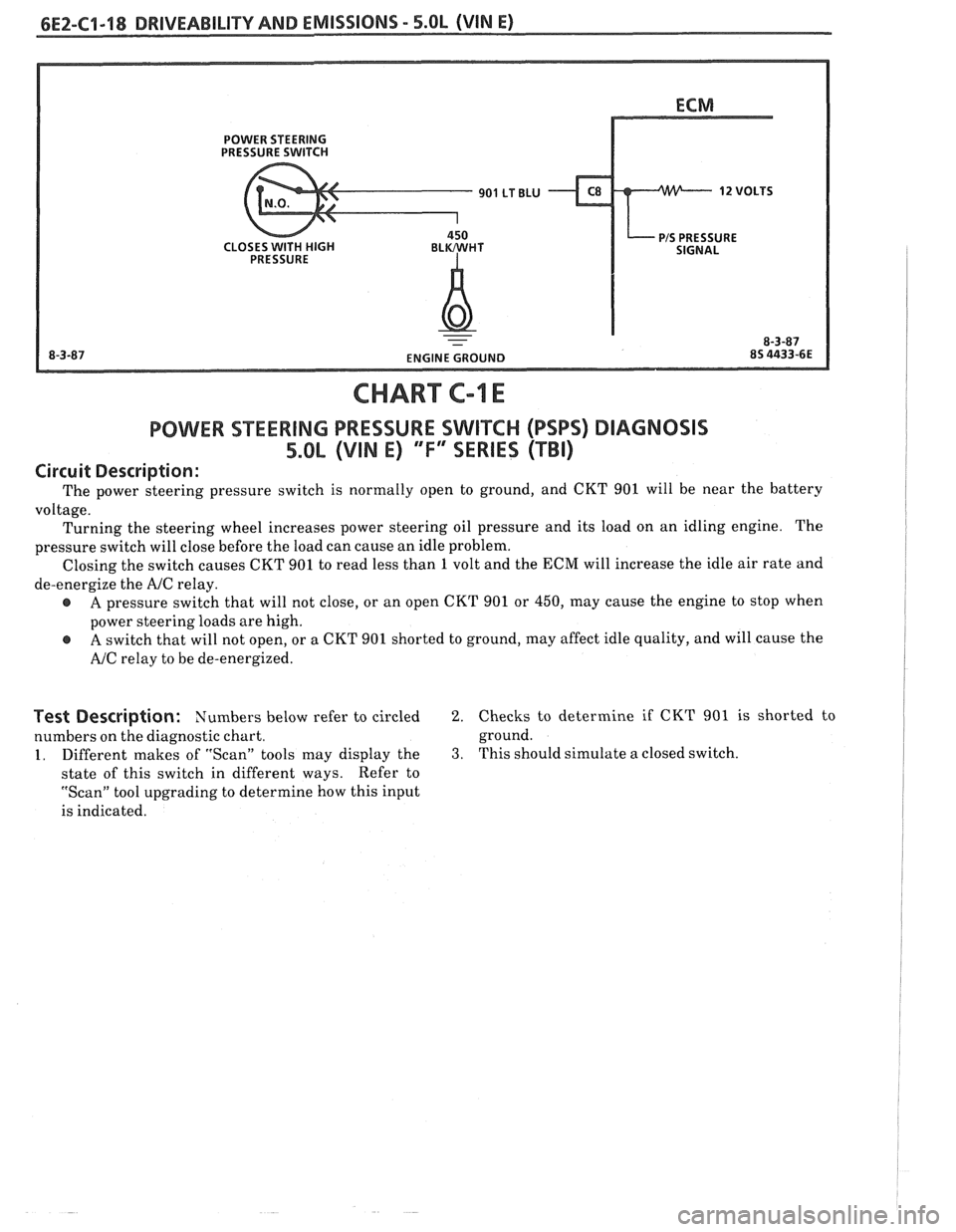
CHART C-1 E
POWER SEERING PRESSURE SWIKCH (PSPS) DIAGNOSIS
5.0L (VIN E) "F" SERIES (TBI)
Circuit Description:
The power steering pressure switch is normally open to ground, and CKT 901 will be near the battery
voltage. Turning the steering wheel increases power steering oil pressure and its load on an idling engine. The
pressure switch will close before the load can cause an idle problem.
Closing the switch causes CKT 901 to read less than
1 volt and the ECM will increase the idle air rate and
de-energize the
AJC relay.
A pressure switch that will not close, or an open CKT 901 or 450, may cause the engine to stop when
power steering loads are high.
A switch that will not open, or a CKT 901 shorted to ground, may affect idle quality, and will cause the
AJC relay to be de-energized.
Test Description: Numbers below refer to circled 2. Checks to determine if CKT 901 is shorted to
numbers on the diagnostic chart. ground.
1. Different
makes of "Scan" tools may display the 3. This should simulate a closed switch.
state of this switch in different ways. Refer
to
"Scan" tool upgrading to determine how this input
is indicated.
Page 574 of 1825
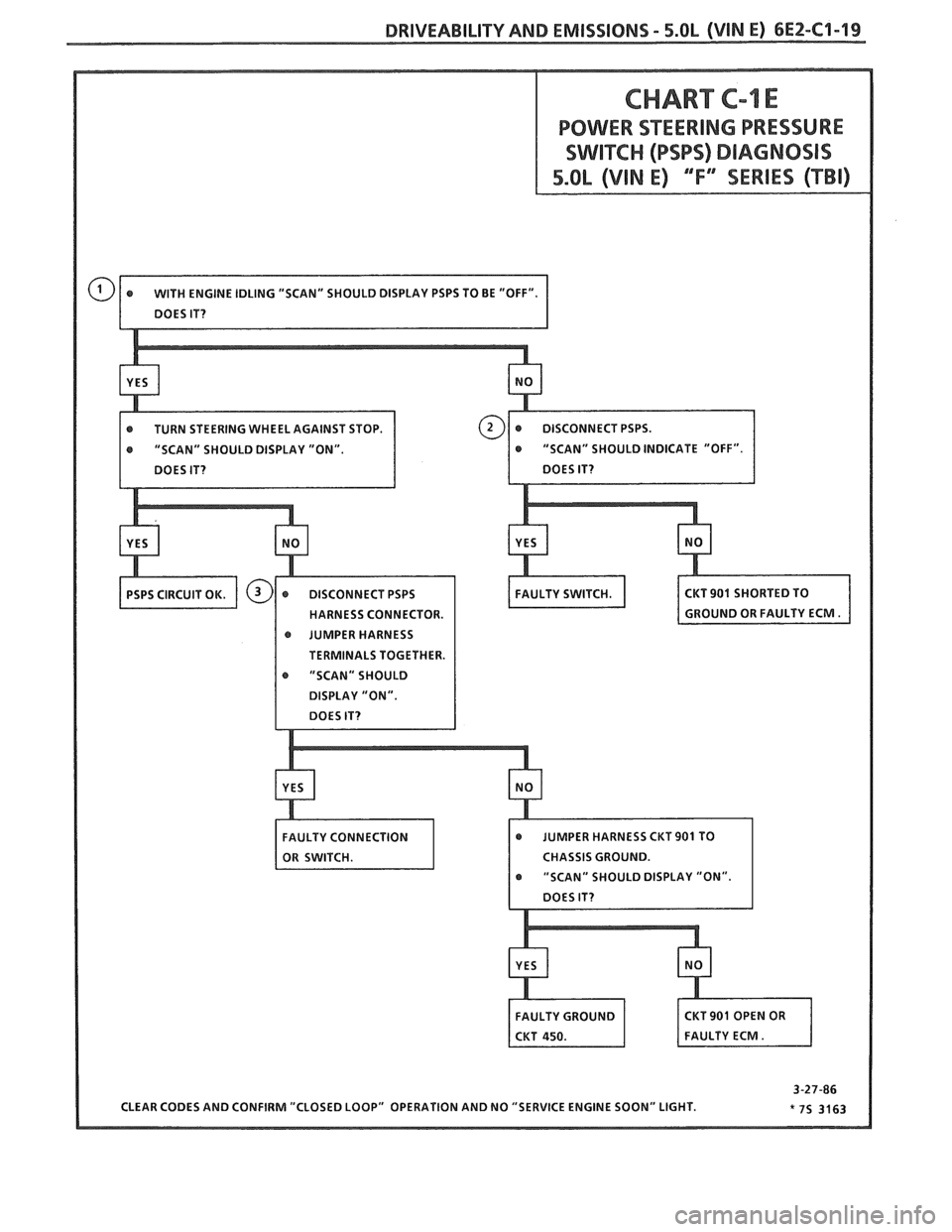
DRIVEABILITY AND EMISSIONS - 5.OL (VIN E) 6E2-C1-19
CHART C-1 E
BOWER SEERING PRESSURE
r TURN STEERING WHEEL AGAINST STOP.
@ JUMPER HARNESS
r "SCAN" SHOULD
CHASSIS GROUND.
Page 724 of 1825
DRIVEABILITY AND EMlSSlQNS 2.8L (VIN S) 6E3-C1-5
ECM Inputs
All of the sensors and input switches can be
diagnosed by the use of a "Scan" tool. Following is a
short description of how the sensors and switches can
be diagnosed by the use of "Scan".
The "Scan" can
also be used to compare the values for a normal
running engine with the engine you're diagnosing.
Coolant Temperature Sensor
A "Scan" tool displays engine temperature in
degrees centigrade. After
engine is started, the
temperature should rise steadily to about 90°C then
stabilize when thermostat opens. If the engine has not
been run for several hours (overnight) the coolant
temperature and MAT temperatures should read close
to each other. A fault in the coolant sensor circuit
should set a Code
14 or 15. The code charts also
contain a chart to check for sensor resistance values
relative to temperature.
MAF Sensor
A "Scan" tool reads the MAF value and displays it
in grams per second. Should read between 4-7 on a
fully warmed up idling engine. Values should change
rather quickly on acceleration, but values should
remain fairly stable at any given RPM. Most "Scan"
tools will have 2 positions for reading
MAE' sensor
values. (MAF
& Air Flow). Both values should read
the same if no Code 33 or 34 is set, but if a code is set,
the MAF values will be the default value and the Air
Flow parameter will lock in on the value to which the
ECM recognized the fault. A failure in the MAF
sensor or circuit should set a Code 33 or 34.
MAT Sensor
A "Scan" tool displays temperature of the air
entering the engine and should read close to ambient
air temperature when engine is cold, and rise as
underhood temperature increases. If the engine has
not been run for several hours (overnight) the MAT
sensor temperature and coolant temperature should
read close to each other. A failure in the MAT sensor
circuit should set
a Code 23 or 25. The code charts also
contain a chart to check for sensor resistance values
relative to temperature.
02 Sensor
The "Scan" has several positions that will indicate
the state of the exhaust gases,
O1! voltage, integrator,
and block learn. See "Scan" position information in
"Introduction," Section
"6E".
A problem in the O2 sensor circuit, or fuel system,
should set a Code 13 (open circuit), Code 44 (lean
indication), Code 45 (rich indication). Refer to
applicable chart if any of these codes
were stored in
memory.
TPS
A "Scan" tool displays throttle position in volts.
You should read
.55V f .08V, with throttle closed and
ignition on, or at idle. Voltage should increase at
a
steady rate as throttle is moved toward WOT.
The ECM has the ability to Auto-Zero the TPS
voltage if it is below about .7V (700
mV). This means
that any voltage less than
.7 volts will be determined
by the ECM to be
0% throttle. A failure in the TPS or
circuit should set a Code 21 or 22.
A "Scan" tools reading should closely match with
speedometer reading with drive wheels turning.
A
failure in the VSS circuit should set a Code 24.
PIN Switch
A "Scan" tool should read PIN when in Park, or
Neutral, and R-D, L, when in Drive or Overdrive.
This reading may vary with different makes of tools.
Refer to CHART
C-1A for PIN switch diagnosis.
NC Request Signal
"Scan" tool should indicate A/C request "ON,"
when A/C is requested and the pressure cycling switch
is closed.
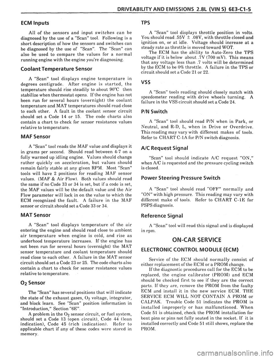
Power Steering Pressure Switch
A "Scan" tool should read "OFF" normally and
"ON" with high pressure. This reading may vary with
different make of tools. Refer to CHART
C-1E for
PSPS diagnosis.
Reference Signal
A "ScanJ' tool will read this signal and is displayed
in rpm.
ON-CAR SERVICE
ELECTRONIC CONTROL MODULE (ECM)
Service of the ECM should normally consist of
either replacement of the ECM or a PROM change.
If the diagnostic
procedures call for the ECM to be
replaced, the engine calibrator (PROM) and ECM
should be checked first to see if they are the correct
parts. If they are, remove the PROM from the faulty
ECM
and install it in the new service ECM. THE
SERVICE ECM WILL NOT CONTAIN A PROM or
CALPAK. Trouble Code 51 indicates the PROM is
installed improperly or has malfunctioned. When
Code
51 is obtained, check the PROM installation for
bent pins or pins not fully seated in the socket. If it is
installed correctly and Code 51 still shows, replace the
PROM.
Page 733 of 1825
6E3-C4-14 2.8L (VIN S) BWiVEABlLlPV AND EMISSIONS
POWER STEERING
PRESSURE SWITCH
PIS PRESSURE
CLOSES
WITH HIGH BLWHT
PRESSURE
-
CHART C-1 E
POWER STEERING PRESSURE SWITCH
2.8L (VIN S) "F"" SERIES (PORT)
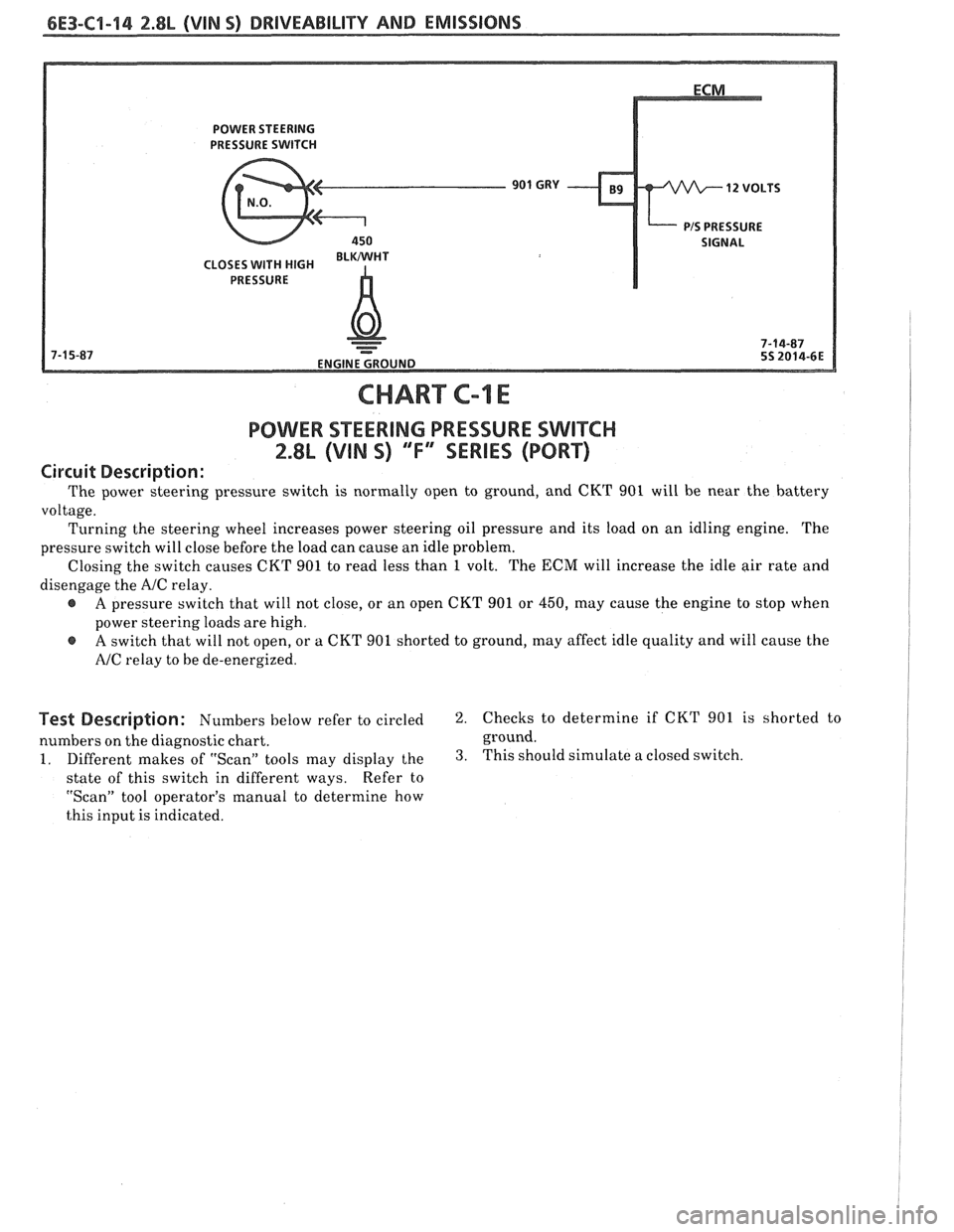
Circuit Description:
The power steering pressure switch is normally open to ground, and CKT 901 will be near the battery
voltage. Turning the steering wheel increases power steering oil pressure and its load on an idling engine. The
pressure switch will close before the load can cause an idle problem.
Closing the switch causes CKT 901 to read less than
1 volt. The ECM will increase the idle air rate and
disengage the
A/C relay.
e A pressure switch that will not close, or an open CKT 901 or 450, may cause the engine to stop when
power steering loads are high.
@ A switch that will not open, or a CKT 901 shorted to ground, may affect idle quality and will cause the
NC relay to be de-energized.
Bescription: Numbers below refer to circled 2. Checks to determine if CKT 901 is shorted to
numbers on the diagnostic chart. ground.
1. Different makes of "Scan" tools may display the 3. This should simulate
a closed switch.
state of this switch in different ways. Refer
to
"Scan" tool operator's manual to determine how
this input is indicated.
Page 972 of 1825
DRIVEABILITY AND EMISSIONS - FUEL INJEC"F0N 6E-11
@ A/% "On" or "Off" r Air Management
r Engine Coolant Temwrature r Canister Purge
@ Engine crank signal r Exhaust Gas Recirculation (EGR)
@ Exhaust Oxygen(02) Sensor @ Electronic Spark Timing (EST)
r Distributor Reference @ Fuel Control
@ Crankshaft Position @ Idle Air Control (lAC)
@ Engine Speed (RPM) Transmission Converter Clutch (TCC)
Manifold Absolute Pressure (MAP)
@ Park Neutral Switch (PB) Position @ Electric Fuel Pump
r System Voltage Air Conditioning
r Throttle Position (TPS) @ Engine Cooling Fan
r Transmission Gear Position
r Vehicle Speed (VSS) @ "Service Engine Soon" Light
@ Fuel Pump Voltage @ Diagnostic Terminal (ALDL)
r Power Steering Pressure @ Data Output (ALDL)
Mass Air Flow (MAF) @ Electronic Spark Control (ESC)
@ Manifold Air Temperature (MAT) @ Early Fuel Evaporation (EFE)
r EGR Vacuum @ Idle Speed (ISC, ILC,)
@ Engine Knock (ESC)
r Differential Pressure (VAC) 6-1-87
*7S
3429- 6E
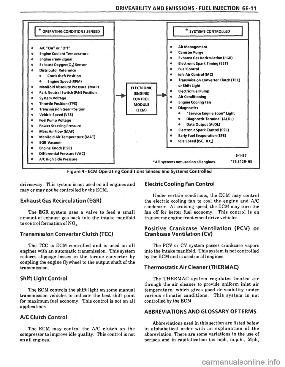
Figure
4 - ECM Operating Conditions Sensed and Systems Controlled
driveaway. This system is not used on all engines and Electric Cooling Fan Control
may or may not be controlled by the ECM.
Under certain conditions, the
ECM may control
Exhaust Gas Recirculation (ECR) the electric cooling fan to cool the engine and A/C
condenser. At cruising speed, the ECM may turn the
The
EGR system uses a valve to feed a small fan
off for better fuel economy. This control is on
amount of exhaust gas back into the intake manifold transverse
engine front wheel drive vehicles.
to control formation of
NO,.
Positive Crankcase Ventilation (PCV) or
Transmission Converter
Clutch (TCC) Crankcase Ventilation (CV)
The TCC is ECM controlled and is used on all
engines with an automatic transmission. This system
reduces slippage losses in the torque converter by
coupling the engine flywheel to the output shaft of the
transmission.
Shift Light Control
The ECM controls the shift light on some manual
transmission vehicles to indicate the best shift point
for maximum fuel economy. This control is not on all
applications.
NC Clutch Control
The ECM may control the AJC clutch on the
compressor to improve idle quality. This control is not
on all engines. The
PCV or CV system passes crankcase vapors
into the intake manifold. This system is not controlled
by the
ECM and is used on all engines.
Thermostatic Air Cleaner (THERMAC)
The THERMAC system regulates heated air
through the air cleaner to provide uniform inlet air
temperature, which gives good driveability under
various climatic conditions. This system is not
controlled by the
ECM.
ABBREVIATIONS AND GLOSSARY OF TERMS
Abbreviations used in this section are listed below
in alphabetical order with an explanation of the
abbreviation. There are some variations in the use of
periods and in capitalization (as mph,
m.p.h., Mph,