1988 PONTIAC FIERO steering wheel
[x] Cancel search: steering wheelPage 197 of 1825
3B7-4 POWER STEERING
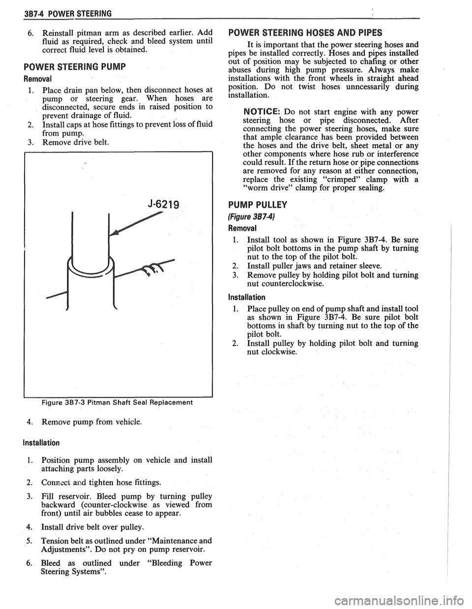
6. Reinstall pitman arm as described earlier, Add
fluid as required, check and bleed system until
correct fluid level is obtained.
POWER STEERING PUMP
Removal
1. Place drain pan below, then disconnect hoses at
pump or steering gear. When hoses are
disconnected, secure ends in raised position to
prevent drainage of fluid.
2. Install caps at hose fittings to prevent loss of fluid
from pump.
3. Remove drive belt.
Figure 3B7-3 Pitman Shaft Seal Replacement
4. Remove pump from vehicle.
Installation
1. Position pump assembly on vehicle and install
attaching parts loosely.
2. Gonl7.zct and tighten hose fittings.
3. Fill reservoir. Bleed pump by turning pulley
backward (counter-clockwise as viewed from
front) until air bubbles cease to appear.
4. Install drive belt over pulley.
5. Tension belt as outlined under "Maintenance and
Adjustments". Do not pry on pump reservoir.
6. Bleed as outlined under "Bleeding Power
Steering Systems".
POWER STEERING HOSES AND PIPES
It is important that the power steering hoses and
pipes be installed correctly. Hoses and pipes installed
out of position may be subjected to chafing or other
abuses during high pump pressure. Always make
installations with the front wheels in straight ahead
position. Do not twist hoses unncessarily during
installation.
NOTICE: Do not start engine with any power
steering hose or pipe disconnected. After
connecting the power steering hoses, make sure
that ample clearance has been provided between
the hoses and the drive belt, sheet metal or any
other components where hose rub or interference
could result. If the return hose or pipe connections
are removed for any reason at either connection,
replace the existing "crimped" clamp with a
"worm drive" clamp for proper sealing.
PUMP PULLEY
(Figure 38 7-41
Removal
1. Install tool as shown in Figure 3B7-4. Be sure
pilot bolt bottoms in the pump shaft by turning
nut to the top of the pilot bolt.
2. Install puller jaws and retainer sleeve.
3. Remove pulley by holding pilot bolt and turning
nut counterclockwise.
Installation
1. Place
pulley on end of pump shaft and install tool
as shown in Figure 3B7-4. Be sure pilot bolt
bottoms in shaft by turning nut to the top of the
pilot bolt.
2. Install pulley by holding pilot bolt and turning
nut clockwise.
Page 206 of 1825
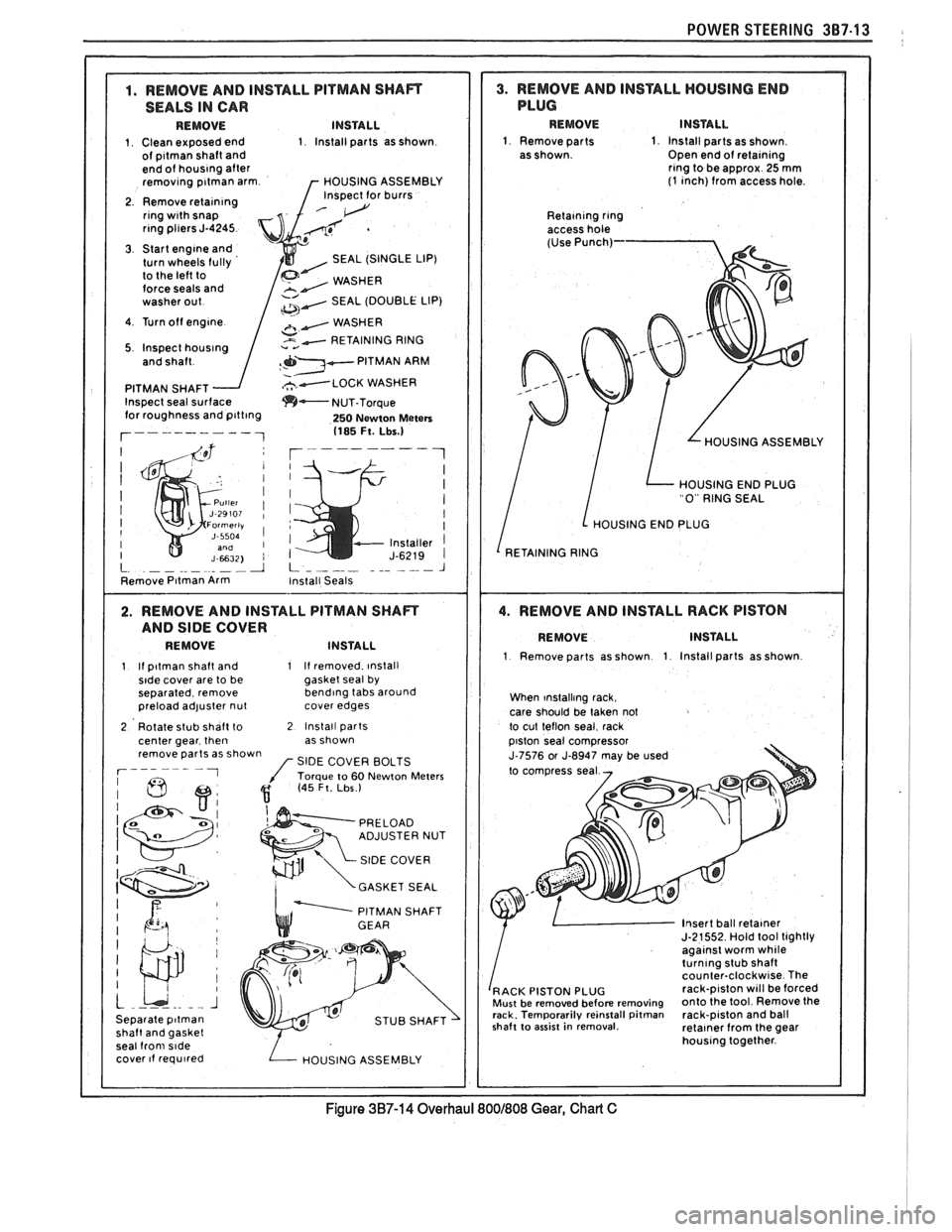
SEALS IN CAR
1 Clean exposed end 1 Install parts as shown 1 Remove parts 1 Install parts as shown of p~tman shaft and Open end of retalnlng end of houslng after rlng to
be approx 25 mm removlng p~tman arm HOUSING ASSEMBLY (1 ~nch) from access hole
2 Remove
retacnlng Inspect for burrs
Reta~ntng rlng rlng pl~ers J-4245
3 Start englne and
turn wheels fully SEAL (SINGLE LIP)
to the left to
force seals and
SEAL (DOUBLE LIP)
4 Turn off
englne
5 Inspect houslng
PITMAN SHAFT
Inspect seal sur
250 Newton Meters 1185 Ft. Lbs.) OUSING ASSEMBLY
HOUSING END PLUG
0 RING SEAL
HOUSING END PLUG
INSTALL
1 Remove parts as shown 1 Install parts as shown 1 If p~tman shaft and 1 If removed ~nstall s~de cover are to be gasket seal
by
separated remove bend~ng tabs around
When ~nstalllng rack.
preload adjuster nut cover edges
care should be taken not
2 Rotate stub shaft to
2 Install parts to cut teflon seal rack
center gear then as shown
remove parts as shown
SIDE COVER BOLTS
GASKET SEAL
PITMAN SHAFT
Insert ball retalner J-21552 Hold 1001 tightly agalnst worm whlle turnlng stub shaft counter-clockw~se The rack-p~ston will be forced
shaft
to asslst in removal. retalner from the gear
seal
from s~de houslng together
cover
lf requ~red
POWER STEERING 387.13
~
I
I
I
I
1
I I
I I
!
I
I
I
I
Figure 3B7-14 Overhaul 8001808 Gear, Chad C
Page 212 of 1825
FRONT SUSPENSION 3C-1
SEC"T0RI 3C
FRONT SUSPENS
NOTICE: All front suspension fasteners are an important attaching part in that it could affect the
performance of vital parts and systems, and/or could result in major repair expense. They must be replaced with
one of the same part number or with an equivalent part if replacement becomes necessary. Do not use a
replacement part of lesser quality or substitute design. Torque values must be used as specified during reassembly
to assure proper retention of this part.
NOTICE: Never attempt to heat, quench or straighten any front suspension part. Replace it with a new part
or
damage to the part may result.
CONTENTS
General lnformation ....................................................................................................... 3C-I
On-Car Service ................................................................................................................... 3C- I
Specifications ..................................................................................................................... 3C- 10
GENERAL INFORMATION
The front suspension is designed to allow each
wheel to compensate for changes in the road surface ON-CAR SERVICE
level without appreciably affecting the opposite wheel. WHEEL BEARINGS
Each wheel is independently connected to the frame by
The proper functioning of the front suspension
a steering
kunckle, strut assembly, ball joint, and lower cannot be maintained unless the front wheel tapered arm. The steering in a roller bearings are correctly adjusted. The bearings
prescribed three dimensional arc. The front wheels are
must be a slip fit on the spindle and the inside diameter held in proper relationship to each other by two tie rods of the bearings should be lubricated to insure proper which are connected to steering arms on the knuckles ~h~ spindle nut must be a free-running fit and to the relay rod assembly.
on the threads.
Coil chassis springs are mounted between the
spring housings on the front crossmember and the
lower control arms. Ride control is provided by double,
direct acting strut assemblies. The upper portion of
each strut assembly extends through the fender well
and attaches to the upper mount assembly with a nut.
Side roll of the front suspension is controlled by
a spring steel stabilizer shaft. It is mounted in rubber
bushings which are held to the frame side rails by
brackets. The ends of the stabilizer are connected to the
lower control arms by link bolts and are isolated by
rubber grommets.
The inner ends of the lower control arms have
pressed in bushings. Bolts (passing through the
bushings) attach the arm to the suspension
crossmember. The lower ball joint assembly is a press
fit in the arm and attaches to the steering knuckle with
a torque prevailing nut.
Rubber grease seals are provided at ball socket
assemblies to keep dirt and moisture from entering the
joint and damaging bearing surfaces.
Adjustment
Figure 602
NOTICE: See NOTICE on Page 3C-1
of this
section.
1. Remove dust cap from hub.
2. Remove cotter pin from spindle and spindle nut.
3. Tighten the spindle nut to 16 Nsm (12 lb. ft.)
while turning the wheel assembly forward by
hand to fully seat the bearings. This will remove
any grease or burrs which could cause excessive
wheel bearing play later.
4. Back off the nut to the "just loose" position.
5. Hand tighten the spindle nut. Loosen spindle nut
until either hole in the spindle lines up with a slot
in the nut. Not
nlore than 1/2 flat.
6. Install
new cotter pin. Bend the ends of the cotter
pin against nut, cut off extra length to ensure ends
will not interfere with the dust cap.
7. Measure the looseness in the hub assembly. There
will be
from .03 to . l3mm (.001 to .005 inches)
end play when properly adjusted.
8. Install dust cap on hub.
FRONT SUSPENSION
Refer to Fig. 610 for illustration of attachment
provisions for the bolted-on front suspension
suspension
crossmember.
Page 217 of 1825
3C-6 FRONT SUSPENSION
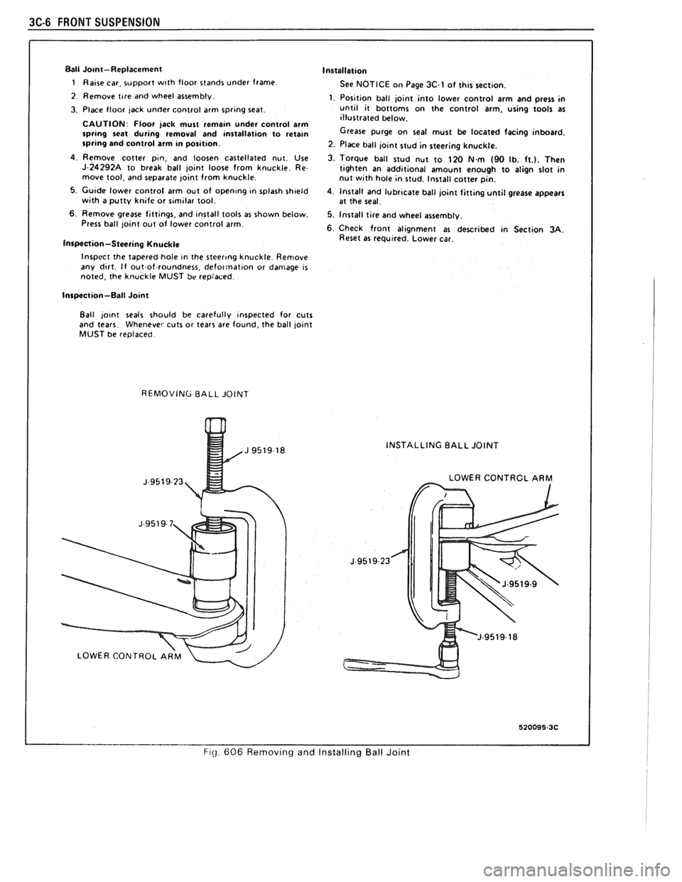
Ball Jo~nt-Replacement
1 Raise car, support w~th floor stands under frame
2 Remove tlre and wheel assembly.
3. Place floor jack under control arm sprtng seat
CAUTION Floor jack must
remaln under control arm sprbng seat dur~ng removal and tnstallat~on to retam sprlng and control arm In posttlon.
4 Remove cotter ptn, and loosen castellated nut Use J 24292A to break ball jolnt loose from knuckle Re
move tool, and separate jolnt from knuckle
5 Gu~de lower control arm out of openlng In splash sh~eld w~th a putty kntfc or stmtlar tool
6 Remove grease fttt~ngs, and ~nstall tools as shown below.
Press ball jolnt out of lower control arm
Inspection-Steering Knuckle
Installation
See NOTICE on Page 3C.1 of this section.
1. Position ball joint into lower control arm and press in
until it bottoms on the control arm, using tools as
illustrated below.
Grease purge on seal must be located facing inboard.
2. Place ball joint stud in steering knuckte.
3. Torque ball stud nut to 120
Nm (90 Ib. ft.). Then
tighten an additional amount enough to align slot in
nut with hole in stud. Install cotter pin.
4, Install and lubrtcate ball joint fitting until grease appears
at the seal.
5. Install tire and wheel assembly.
6. Check front alignment as described in Section 3A. Reset as requrred. Lower car.
Inspect the tapered hole
In the stcerlng knuckle Remove
any dtrt. If out.of-roundness, defor:nat~on or damage IS noted, the knuckle MUST be replaced
Inspection-Ball Joint
Ball
jo~nt seals should be carefully inspected for cuts
and tears. Whenever cuts or tears are found, the ball joint
MUST be replaced.
REMOVING BALL JOINT
INSTALLING BALL JOINT
LOWER CONTRCL ARM
FI~ 606 Remov~ng and Installing Ball Joint
Page 234 of 1825
TIRES AND WHEELS 3E-3
METRIC WHEEL NUTS AND STUDS
Some models use metric wheel nuts and wheel
studs. The nut will have the word "metric" stamped on
its face and the stud will have the letter
"M" stamped
into the threaded end. The word "metric" is stamped
on its head.
The thread size of the metric wheel nuts and
wheel studs are
"MI2 x 1.5". These stand for:
M = Metric
12
= Diameter in millimeters
1.5
= Millimeters per thread
If a broken stud is found, see Section 3C (Front
Suspension) or Section 3D (Rear Suspension) for
replacement procedure.
INFLATION OF TIRES
The pressure recommended for any model is
carefully calculated to give a satisfactory ride,
handling, tread life and load carrying capacity.
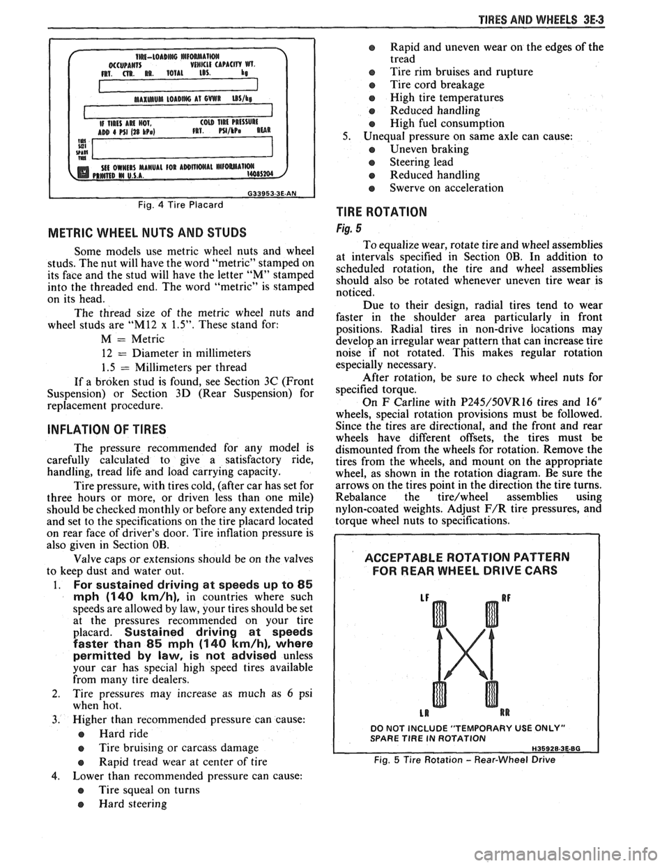
Tire pressure, with tires cold, (after car has set for
three hours or more, or driven less than one mile)
should be checked monthly or before any extended trip
and set to the specifications on the tire placard located
on rear face of driver's door. Tire inflation pressure is
also given in Section OB.
Valve caps or extensions should be on the valves
to keep dust and water out.
1. For sustained driving at speeds up to 85
mph (140 km/h), in countries where such
speeds are allowed by law, your tires should be set
at the pressures recommended on your tire
placard.
Sustained driving at speeds
faster than
85 mph (140 km/h), where
permitted
by law, is not advised unless
your car has special high speed tires available
from many tire dealers.
2. Tire pressures may increase as much as 6 psi
when hot.
3. Higher
than recommended pressure can cause:
o Hard ride
o Tire bruising or carcass damage
Rapid tread wear at center of tire
4. Lower
than
recommended pressure can cause:
@ Tire squeal on turns
@ Hard steering
o Rapid and uneven wear on the edges of the
tread
Tire rim bruises and rupture
e Tire cord breakage
o High tire temperatures
o Reduced handling
High fuel consumption
5. Unequal pressure on same axle can cause:
Uneven braking
o Steering lead
o Reduced handling
e Swerve on acceleration
TlRE ROTATION
Fig. 5
To equalize wear, rotate tire and wheel assemblies
at intervals specified in Section OB. In addition to
scheduled rotation, the tire and wheel assemblies
should also be rotated whenever uneven tire wear is
noticed.
Due to their design, radial tires tend to wear
faster in the shoulder area particularly in front
positions. Radial
tires in non-drive
iocations may
develop an irregular wear pattern that can increase tire
noise if not rotated. This makes regular rotation
especially necessary.
After rotation, be sure to check wheel nuts for
specified torque.
On
F Carline with P245/50VR16 tires and 16"
wheels, special rotation provisions must be followed.
Since the tires are directional, and the front and rear
wheels have different offsets, the tires must be
dismounted from the wheels for rotation. Remove the
tires from the wheels, and mount on the appropriate
wheel, as shown in the rotation diagram. Be sure the
arrows on the tires point in the direction the tire turns.
Rebalance the
tire/wheel assemblies using
nylon-coated weights. Adjust
F/R tire pressures, and
torque wheel nuts to specifications.
ACCEPTABLE ROTATION PATTERN
FOR REAR WHEEL
DRIVE GARS
DO NOT INCLUDE "TEMPORARY USE ONLY" SPARE TlRE IN ROTATION
Fig. 5 Tire Rotation - Rear-Wheel Drive
Page 308 of 1825
BRAKES 5-15
lnspect rear drum brake shoe and lining assemblies.
Install or Connect (Figures 12 and 13)
When the thickness of any lining is worn within 0.76 mm
Raise vehicle. See Section OA. (0.030-inch)
of the shoe or rivet, the shoe and lining
1. Cable at brake shoe operating lever. assemblies must
be replaced. Replace shoe and lining
Bend retainer fingers. assemblies
in axle sets.
2. Brake drum and wheel.
3. Rear cable at connector.
0 Lower vehicle. See Section oA. INSPECTING AND REFINISHING ROTORS
Adjust
0 Parking brake. See Section 5C3.
Parking Brake Rear Cable (Disc Brakes)
Remove or Disconnect (Figures
12 and 13)
0 Raise vehicle. See Section OA.
1. Rear cable from connector.
0 Loosen adjusting nut at equalizer.
2. Cable from brake caliper.
Push forward on caliper parking brake apply
lever.
@ Remove cable from tang in lever.
Release lever.
Lower vehicle. See Section OA.
Install or Connect (Figures 12 and
13)
Raise vehicle. See Section OA.
1. Cable to brake caliper.
0 Push forward on caliper parking brake apply
lever.
0 Install cable in lever tang.
Release lever.
2. Rear cable to connector. 0 Lower vehicle. See Section OA.
0 Parking brake. See Section 586.
BRAKE LINING INSPECTION
(Figure 14)
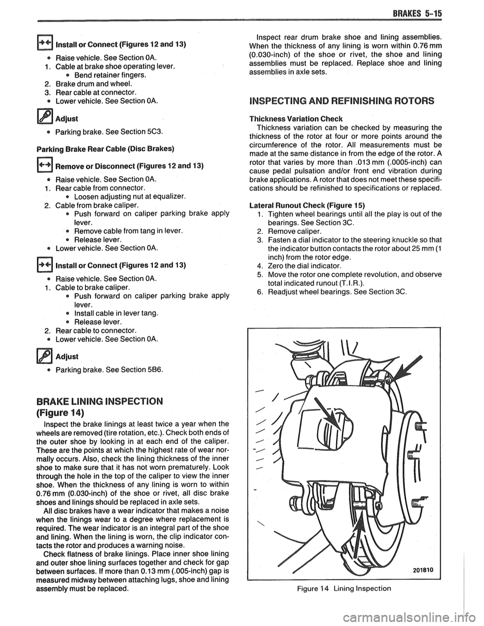
lnspect the brake linings at least twice a year when the
wheels are removed (tire rotation, etc.). Check both ends of
the outer shoe by looking in at each end of the caliper.
These are the points at which the highest rate of wear nor-
mally occurs. Also, check the lining thickness of the inner
shoe to make sure that it has not worn prematurely. Look
through the hole in the top of the caliper to view the inner
shoe. When the thickness of any lining is worn to within
0.76
mm (0.030-inch) of the shoe or rivet, all disc brake
shoes and linings should be replaced in axle sets.
All disc brakes have a wear indicator that makes a noise
when the linings wear to a degree where replacement is
required. The wear indicator is an integral part of the shoe
and lining. When the lining is worn, the clip indicator con-
tacts the rotor and produces a warning noise.
Check flatness of brake linings. Place inner shoe lining
and outer shoe lining surfaces together and check for gap
between surfaces. If more than 0.13 mm
(.OO&inch) gap is
measured midway between attaching lugs, shoe and lining
assembly must be replaced. Thickness
Variation Check
Thickness variation can be checked by measuring the
thickness of the rotor at four or more points around the
circumference of the rotor. All measu'rements must be
made at the same distance in from the edge of the rotor. A
rotor that varies by more than
.013 mm (.0005-inch) can
cause pedal pulsation
and/or front end vibration during
brake applications. A rotor that does not meet these specifi-
cations should be refinished to specifications or replaced.
Lateral
Wunout Check (Figure 15)
1. Tighten wheel bearings until all the play is out of the
bearings. See Section 3C.
2. Remove caliper.
3. Fasten a dial indicator to the steering knuckle so that
the indicator button contacts the rotor about
25 mm (1
inch) from the rotor edge.
4. Zero the dial indicator.
5. Move the rotor one complete revolution, and observe
total indicated
runout (T.I.R.).
6. Readjust wheel bearings. See Section 3C.
Figure 14 Lining Inspection
Page 376 of 1825
2.8 LITER V-6 6A2-25
Fitting
1. Select rings comparable in size to the piston being
used.
2. Slip
the compression ring in the cylinder bore;
then press the ring down into the cylinder bore
about 6mm above ring travel. Be sure ring is
square with cylinder wall.
3. Measure the space or gap between the ends of the
ring with a feeler gage (Figure
6A2-33).
4. If
the gap between the ends of the ring is below
specifications, remove the ring and try another
for fit.
5. Fit each compression ring to the cylinder in
which it is going to be used.
6. If the pistons have not been cleaned and inspected
as previously outlined, do so.
7. Slip the outer surface of the top and second
compression ring into the respective piston ring
groove and roll the ring entirely around the
groove (Figure
6A2-34). If binding occurs at any
point, the cause should be determined. If there is
a ring groove, remove by dressing with a fine cut
file. If the binding is caused by a distorted ring,
check a new ring.
Installation
1. Install oil ring spacer in groove being sure ends
are butted and not overlapped.
2. Hold
spacer ends butted and install lower steel oil
ring rail.
3. Install upper
steel oil ring rail with gap staggered.
4. Flex
the oil ring assembly to make sure ring is
free. If binding occurs, the cause should be
detemined. If caused by ring groove, remove by
dressing groove with a fine cut file. If binding is
caused by a distorted ring, check a new ring.
5. Install second compression ring. Stagger gap
from other rings.
6. Install top compression ring with gap properly
located.
ENGINE ASSEMBLY
Removal
Disconnect battery.
Remove air cleaner.
Remove hood. Drain radiator.
Remove lower radiator hose.
Remove upper fan shroud.
Remove upper radiator hose and coolant
recovery hose.
Remove transmission cooler lines. Remove radiator.
Remove fan assembly.
Remove heater hoses.
Disconnect carburetor linkage, includes cruise
control detent cable.
Remove vacuum brake booster line.
Remove distributor cap and lay wiring aside.
Disconnect necessary wires and hoses.
Remove power steering pump and lay aside. Raise
vehicle.
Remove exhaust pipes at exhaust manifold.
Remove dust cover.
Remove converter bolts.
Disconnect starter wires.
Remove bell housing bolts.
Remove motor mount through bolts.
Disconnect fuel lines at fuel pump.
Lower vehicle. Support transmission.
Remove
A.I.R./Converter pipes bracket.
Remove engine, include removing wire from
bracket at rear left of engine.
Installation
Position engine assembly in vehicle.
Attach motor mount to engine brackets and
lower engine in place.
Remove engine lifting device.
Remove transmission floor jack.
Raise vehicle on hoist.
Install mount "through" bolts. Torque to
specifications.
Install bell housing bolts. Torque to
specifications.
On vehicles with automatic transmission, install
converter to flywheel attaching bolts. Torque to
specifications.
Install flywheel splash shield of conveter housing
cover as applicable. Torque attaching bolts to
specifications.
Install starter wires.
Connect fuel lines.
Connect exhaust pipe at manifold.
Lower vehicle on hoist.
Reinstall power steering pump, if so equipped.
Connect necessary wires and hoses.
Install radiator and fan shroud and reconnect
radiator and heater hoses.
Fill cooling system.
Fill crankcase with oil. See owner's manual for
specifications.
Install air cleaner.
Install hood.
Connect battery cables.
NOTICE: To avoid possible arcing of battery,
connect positive battery cable first.
22. Start engine, check for leaks and check timing.
CRANKSHAFT
The crankshaft can be removed while the engine
is dissasembled for overhaul, as previously outlined or
without complete disassembly.
Removal
1. With the engine removed from the vehicle,
remove the clutch assembly (if equipped) and
flywheel. Mount engine in stand and clamp
securely.
Page 406 of 1825
V-8 ENGINE 6A3-27
3. When finish honing
a cylinder bore to fit a piston,
the hone should be moved up and down at a
sufficient speed to obtain very fine uniform
surface finish marks in a cross-hatch pattern of
approximately
45" to 65" included angle. The
finish marks should be clean but not sharp, free
from imbedded particles and torn or folded
metal.
4. Permanently mark
the piston for the cylinder to
which it has been fitted and proceed to hone
cylinders and fit the remaining pistons.
NOTICE: Handle the pistons with care and do not
attempt to force them through the cylinder until
the cylinder has been honed to correct size as this
type piston can be distorted through careless
handling.
5. Thoroughly
clean the bores with hot water and
detergent. Scrub well with a stiff bristle brush and
rinse thoroughly with hot water. It is extremely
essential that a good cleaning operation be
performed. If any of the abrasive material is
allowed to remain in the cylinder bores, it will
rapidly wear the new rings and cylinder bores in
addition to the bearings lubricated by the
contaminated oil, the bores should be swabbed
and then wiped with a clean dry cloth. Cylinder
should not be cleaned with kerosene or gasoline.
Clean the remainder of the cylinder block to
remove the excess material spread during the
honing operation.
Piston Selection
1. Check USED piston to cylinder bore clearance as
follows:
a. Measure
the "Cylinder Bore Diameter"
with a telescope gage
"2-1/2" (64mm) from
top of cylinder bore").
b. Measure
the
"Piston Diameter" (at skirt
across center line of piston pin).
c. Subtract
piston diameter from cylinder bore
diameter to determine "Piston to Bore
Clearance".
d. Determine if piston to bore clearance is in
the acceptable range.
2. If
used piston is not acceptable, check Piston Size
Chart and determine if a new piston can be
selected to fit cylinder bore within the acceptable
range.
3. If
cylinder bore must be reconditioned, measure
new piston diameter (across center line of piston
pin) then hone cylinder bore to correct clearance
(preferable range).
4. Mark the piston to identify the cylinder for which
it was fitted.
OIL FILTER BYPASS VALVE
Inspection and Replacement
With the oil filter removed, check the spring and
fibre valve for operation. Inspect for a cracked or
broken valve. If replacement is necessary, the oil filter
adapter and bypass valve assembly must be replaced as an
assembly. Clean valve chamber in cylinder block
thoroughly. Torque retaining screws to specifications.
ENGINE ASSEMBLY
Removal
1. Disconnect battery.
2. Remove air cleaner.
3. Remove hood.
4. Drain radiator.
5. Remove lower radiator hose.
6. Remove upper fan shroud.
7. Remove upper radiator hose and coolant
recovery hose.
8. Remove transmission cooler lines.
9. Remove radiator.
10. Remove fan assembly.
1 1. Remove heater hoses.
12. Disconnect
carburetor linkage, includes cruise
control detent cable.
13. Remove vacuum brake booster line.
14. Remove
distributor cap and lay wiring aside.
15. Disconnect necessary wires and hoses.
16. Remove power steering
pump and lay aside.
17. Raise vehicle.
18. Remove exhaust
pipes at exhaust manifold.
19. Remove dust cover.
20. Remove converter bolts.
2 1. Disconnect starter wires.
22. Remove bell housing bolts.
23. Remove
motor mount through bolts.
24. Disconnect fuel lines
at fuel pump.
25. Lower vehicle.
26. Support transmission.
27. Remove
A.I.R./Converter pipe bracket.
28. Remove engine, include removing wire
from
bracket at rear left of engine.
Installation
1. Position engine
assembly in vehicle.
2. Attach
motor mount to engine brackets and
lower engine in place.
3. Remove engine lifting device.
4. Remove transmission floor jack.
5. Raise vehicle on hoist.
6. Install mount "through" bolts. Torque to
specifications.
7. Install bell housing bolts. Torque to
specifications.
8. On vehicles with automatic transmissions, install
I
converter to flywheel attaching bolts. Torque to
specifications.
9. Install flywheel splash shield of converter
housing cover as applicable. Torque attaching
bolts to specifications.
I
10. Install starter wires.
1 1. Connect fuel lines.
12. Connect exhaust pipe at manifold.
13. Lower vehicle on hoist.
14. Reinstall power steering pump, if so equipped.
15. Connect necessary wires and hoses.