1988 PONTIAC FIERO run flat
[x] Cancel search: run flatPage 22 of 1825
MAINTENANCE AND LUBRICATION OB-5
Throttle linkage inspection -- Inspect for inter-
ference, binding, damaged or missing parts.
Engine drive belts inspection - Inspect all
belts for cracks, fraying and wear. Adjust or replace as
needed.
Rear axle service (if equipped) - Check gear
lubricant level and add if needed. For cars equipped with a
limited slip rear axle, fluid does not require changing
(except Caprice and Corvette
- change fluid and required
additive at first
7,500 miles (12 500 km). See your
Owner's Manual or "Recommended Fluids
& Lubricants
Chart" in this section.
IF YOU USE YOUR GAR TO PULL A TRAILER,
CHANGE GEAR LUBRICANT EVERY 7,500 MILES
(12 500 KM).
NOTICE: A large loss in this system may indicate a
problem. Have it inspected and repaired at once.
Power antenna - Clean and then lubricate power
antenna mast. The proper lubricant as shown in Figure
OB-2 should be used.
AT LEAST ONCE A YEAR
Lap and shoulder belts condition and opera-
tion
- Inspect belt system, including webbing, buckles,
latch plates, retractors, guide loops and anchors.
Moveable head restraint operation - On cars
with moveable restraints, make sure restraints stay in the
desired position. (See adjustment instructions in your
Owner's Manual.)
Seatback latch and recliner operation on
cars equipped
with recliner seat --- Be sure seat-
backs latch on those cars with folding seats using mechan-
ical latches. Make sure the recliner is holding by pushing
and pulling on the top of the
seatback while it is reclined.
See your Owner's Manual for seat operating information.
Spare tire and jack storage- Be alert to rattles
in rear of car. Make sure the space tire, all jacking equip-
ment, any tire inflator and any covers or doors are securely
stowed at all times. Oil jack ratchet or screw mechanism
after each use.
Key lock service - Lubricate key lock cylinder at
least annually.
Body lubrication service - Lubricate all body
door hinges including the tailgate or hatchback lid (if
equipped). Also lubricate the body hood, fuel door and
rear compartment hinges and latches including interior
glove box and counsel doors, and any folding seat
hardware.
"Fansmissionltransaxle neutral or clutch
starl switch operation
CAUnON: Before pedorming the follow-
ing safety switch check, be sure to have
enough room around the car. Then, firmly
apply both the parking brake (see your
Owner's Manual for procedure) and the
regular brakes. Do not use the accelerator pedal.
If the engine
starls, be ready to turn
off the ignition promptly. Take these pre-
cautions because the car could move
without warning and possibly cause per-
sonal injury or properly damage. On auto-
matic transmissionltransaxle cars, try to
starl the engine in each gear. The starler
should crank only in "Park" or "Neutral."
On manual transmissionltransaxle cars,
place the
shiR lever in "Neutral," push the
clutch halfway and try to starl. The starler
should crank only when the clutch is fully
depressed.
Steering column lock operation
- While
parked, try to turn key to "Lock" in each gear range. The
key should turn to "Lock" only when gear is in "Park" on
automatic or "Reverse" on manual
transmissionltransax-
le. On cars with key release lever, try to turn key toULock"
without depressing the lever. The key should turn to
"Lock" only with the key lever depressed. On all vehicles,
the key should come out only in "Lock."
Parking brake and transmissionltransaxle
"Park" mechanism operation
CAUT1ON:Before checking the holding
ability of the parking brake and automatic
transmissionltransaxle "Park" mecha-
nism, park on a fairly steep hill with
enough room for movement in the down-
hill direction. To reduce the risk of person-
al injury or property damage, be prepared
to apply the regular brakes promptly if the
car begins to move.
To check the parking brake, with the engine running and
transmission/transaxle in "Neutral." slowly remove foot
pressure from the regular brake pedal (until the car is held
by only the parking brake).
To check the automatic transmissionltransaxle "Park"
mechanism holding ability, release all brakes after shift-
ing the transmissionltransaxle to "Park."
ljnderbody flushing - At least every spring,
tlush from the underbody with plain water any corrosive
materials used for ice and snow removal and dust control.
Take care to thoroughly clean any areas where mud and
other debris can collect.
Sediment packed in closed areas
of the vehicle should be loosened before being flushed.
Engine cooling system service - Inspect
coolant and freeze protection. If dirty or rusty, drain, flush
and refill with new coolant. Keep coolant
at the proper
mixture as specified in your Owner's Manual. This pro-
vides proper freeze protection. corrosion inhibitor level
and engine operating temperature. Inspect hoses and re-
place if cracked. swollen or deteriorated. Tighten hose
clamps. Clean outside of radiator and air conditioning
condensor. Wash radiator filler cap and neck.
To help
ensure proper operation. a pressure test of both the cooling
system and cap is also recommended. (See maintenance
schedule charts in Figure
OB-l for the recommended
coolant change interval.)
Page 138 of 1825
STEERING, SUSPENSION, TIRES AND WHEELS DIAGNOSIS 3.13
in doubt about the condition, compare with a
shock known to be good.
Noisy
For struts, follow Steps 1 through 3.
1. Check all mountings for proper torque. A loose
mounting will cause a noise.
2. If all mountings are intact, bounce the car as in
Step
4 (weak) to isolate the suspected unit.
3. If practical, ride with the owner to be sure you
understand the complaint, before proceeding to
next step.
4. If one of the rear shocks is noisy, the rear axle
should be supported at least enough to unload the
shock mounts. Disconnect the lower mounting of
the suspected shock. Quickly push the shock all
the way in, then all the way out.
A hissing noise
is normal.
5. Other objectionable noises may be detected by
stroking. Any sound other
than hissing is
abnormal; replace the shock.
Leaks
1. Fully extend the strut/shocks (wheels
unsupported) to expose the seal cover area for
inspection.
2. Look for
signs of leaks in the seal cover area.
3. A slight trace of fluid is NOT cause for
replacement; the seal permits some seepage to
lubricate the piston rod. There is a built in fluid
reserve to allow for seepage.
4. A leaking strut dampener/shock can easily be
found because there will be fluid around the seal
cover and an excessive amount of fluid on the
strut
dampener/shock. A leaking strut
dampener/shock must be replaced.
BENCH CHECKS
Strut Dampeners and Regular Shock Absorbers
(Standard and Firm Ride)
Regular strut dampenerdrear shocks use a
gas-filled cell in the fluid reservoir. Aeration or
foaming of the fluid is eliminated, as the gas and the
fluid cannot mix.
Proceed with the actual bench check as follows:
1. Clamp the strut dampener/shock UPSIDE
DOWN in the vise. Do not clamp on the reservoir
tube or the mounting threads. If a lag is noticed
when it is stroked, it means the gas-filled cell has
ruptured and replacement is necessary.
2. Pump strut dampener/shock by hand at various
rates of speed and note the resistance.
3. Rebound resistance normally is stronger than
compression resistance by about 2 to 1. However,
the resistance should be smooth and constant for
each stroking rate.
4. Compare with a strut dampener/ shock known to
be good.
5. It is normal to hear a hissing noise. The following
symptoms are abnormal and are reason for
replacement. A.
A skip or lag at reversal near mid-stroke.
B. A seize (except at either extreme end of
travel).
C. A noise (such as a grunt or squeal) after
completing one full stroke in both
directions.
D. A clicking noise at fast reversal.
E. Fluid leakage.
TIRE DIAGNOSIS
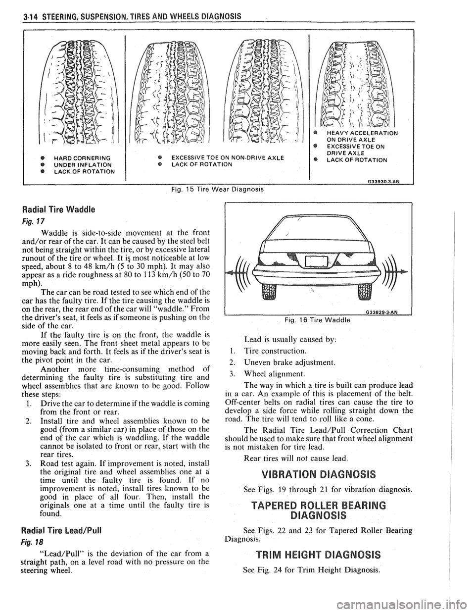
Irregular and Premature Wear
Figs. 14 and 15
Irregular and premature tire wear has many
causes. Some of them are: incorrect inflation pressures,
lack of regular rotation, driving habits, or improper
wheel alignment. If wheel alignment is reset due to a
tire wear condition, always reset toe as close to zero
degrees as the specification allows.
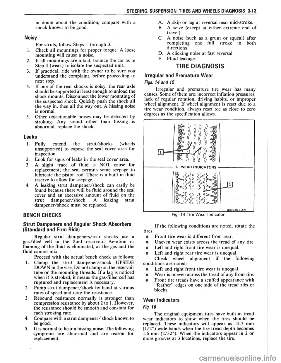
1. WEAR INDICATORS I
Fig. 14 Tire Wear Indicator
If the following conditions are noted, rotate the
tires:
@ Front tire wear is different from rear.
Uneven wear exists across the tread of any tire.
e Left and right front tire wear is unequal.
Left and right rear tire wear is unequal.
Check wheel alignment if the following
conditions are noted:
e Left and right front tire wear is unequal.
Wear is uneven across the tread of any front tire.
e Front tire treads have a scuffed appearance with
"feather" edges on one side of the tread ribs or
blocks.
Wear Indicators
Fig. 16
The original equipment tires have built-in tread
wear indicators to show when the tires should be
replaced. These indicators will appear as 12.7 mm
(1/2") wide bands when the tire tread depth becomes
1.6 mm (2/32"). When the indicators appear in 2 or
more grooves at
3 locations, replace the tire.
Page 139 of 1825
3-14 STEERING, SUSPENSION, TIRES AND WHEELS DIAGNOSIS
@ HARD CORNERING O UNDER INFLATION LACK OF ROTATION
@ HEAVY ACCELERATION ON DRIVE AXLE EXCESSIVE TOE ON DRIVE AXLE EXCESSIVE TOE ON NON-DRIVE AXLE @ LACK OF ROTATION O LACK. OF ROTAT ION
Fig. 15 Tire Wear Diagnosis
Radial Tire Waddle
Fig. 17
Waddle is side-to-side movement at the front
and/or rear of the car. It can be caused by the steel belt
not being straight within the tire, or by excessive lateral
runout of the tire or wheel. It ig most noticeable at low
speed, about 8 to 48
km/h (5 to 30 mph). It may also
appear as a ride roughness at 80 to 113
km/h (50 to 70
mph). The car can be road tested to see which end of the
car has the faulty tire. If the tire causing the waddle is
on the rear, the rear end of the car will "waddle." From
the driver's seat, it feels as if someone is pushing on the
side of the car.
If the faulty tire is on the front, the waddle is
more easily seen. The front sheet metal appears to be
moving back and forth. It feels as if the driver's seat is
the pivot point in the car.
Another more time-consuming method of
determining the faulty tire is substituting tire and
wheel assemblies that are known to be good. Follow
these steps:
1. Drive the car to determine if the waddle is coming
from the front or rear.
2. Install tire and wheel assemblies known to be
good (from a similar car) in place of those on the
end of the car which is waddling. If the waddle
cannot be isolated to front or rear, start with the
rear tires.
3. Road test again. If improvement is noted, install
the original tire and wheel assemblies one at a
time until the faulty tire is found. If no
improvement is noted, install tires known to be
good in place of all four. Then, install the
originals one at a time until the faulty tire is
found.
Radial Tire Lead/Pull
Fig. 18
"Lead/Pull" is the deviation of the car from a
straight path, on a level road with no pressure
on the
steering wheel.
L Fig. 16 Tire Waddle
Lead is usually caused by:
1. Tire construction.
2. Uneven brake adjustment.
3. Wheel alignment.
The way in which a tire is built can produce lead
in a car. An example of this is placement of the belt.
Off-center belts on radial tires can cause the tire to
develop a side force while rolling straight down the
road. The tire will tend to roll like a cone.
The Radial Tire
Lead/Pull Correction Chart
should be used to make sure that front wheel alignment
is not mistaken for tire lead.
Rear tires will not cause lead.
VIBRATION DIAGNOSIS
See Figs. 19 through 21 for vibration diagnosis.
TAPERED ROLLER BEARING
DlAGNOSlS
See Figs. 22 and 23 for Tapered Roller Bearing
Diagnosis.
See Fig. 24 for Trim Height Diagnosis.
Page 143 of 1825
3-18 STEERING, SUSPENSION, TIRES AND WHEELS DIAGNOSIS
VIBRATION COMPLANT TIRE-WHEEL-HUB-AXLE RELATED
Vibrations that are tire or wheel induced can be caused
by two factors: imbalance or
runout. Low-speed vibrations, those less than 40 mph, are
usually runout related. Highway speed vibrations, those
above 40 mph, can be caused by either imbalance or runout. Prior to performing any work, always road test the car
and perform a careful visual inspection for:
- Obvious tire and wheel runout. - Obvious drive 'axle or propeller shaft runout. - Proper inflation pressure. - Wrong trim height. - Bent wheels. - Debris build-up on the tire or wheel. - Loose or missing wheel weights or wheel nuts. - Irregular or excessive tire wear. - Proper tire bead seating on rim. - Damaged tires, such as tread distortions,
separations, or bulges from impact damage. Slight sidewall indentations are normal and will not affect
ride quality.
Balance is the easiest procedure to perform and should,
therefore, be done fist if the vibration occurs at highway
speeds.
An off-car two-plane dynamic balance should first
be performed. This will correct any imbalance in the tire and
wheel assembly.
An oncar fiish balance may also be required. This will correct any brake drum, rotor, or wheel cover imbalance.
Follow the balancing procedures outlined in Section 3E. If balance does not correct the highway speed vibration,
or if the vibration is at low speeds, runout is the probable
cause. Runout can be caused by the tire, wheel, or the way
the wheel attaches to the car. The following procedure
should be used
: A. If runout is suspected, the free runout of the tire
and wheel assembly should first be measured on the car. A
dial indicator with a roller wheel is preferable, but a dial
indicator with button end may be used. Lateral
runout (side
to side) should be measured on the tire's sidewall as close to
the tread shoulder as possible. Radial
runout (up and down)
should be measured on the center tread rib. Some tread
designs may require tightly wrapping a piece of tape around
the center tread circumference for better dial indicator
contact. For measuring wheel
runout follow the "Measuring
Wheel Runout" procedure in Section 3E. Whether measuring
radial or lateral runout, disregard any instantaneous indicator
needle jumps due to sidewall depressions, tread blocks, etc.
Record the total indicator reading, and the location of the
high point of
runout. The,,total tire and wheel oncar runout should be less than ,060 , if either measurement exceeds ,060"~ proceed to Step B.
B. If
the oncy radial or lateral runout measured in
Step A exceeds .060 , mount the tire and wheel assembly on
a dynamic balance machine and again measure the amount of runout. Locate on the machine by the wheel's inside center
pilot hole. Using the same procedure as in Step A, record the
amount of tire and wheel
runout and its high point Location.
Next, measure wheel runout, see Section 3E. If the wheel
exceeds specifications replace the ~heel.,~If the tire and wheel
radial or lateral runout exceeds .050 at the tire tread,
proceed to Step C.
C. If the off-car tire and wheel radial or lateral runout measured in Step 18 exceeds .050", match mount the high radial runout point of tire to low radial runout point of
wheel. Weinflate, mount on the dynamic balance machine,
and again measure and record the radial and lateral runout and its location, as done in Step B. In many cases, match
mounting the tire on the wheel will bring the assembly's
runout into the acceptable range of less than .050". D. If the runout of the tire and wheel assembly is
within limits when measured off the car, yet exceeds the
limits when measured on the car, the attachment of the tire
and wheel assembly to the hub is the probable cause. Rotate
the assembly two wheel studs and recheck the
runout. Several positions may have to be tried to find the best
location.
E. If the assembly runout cannot be reduced to an
acceptable level, remove the tire and wheel assembly and
measure wheel stud
runout with a dial indicator. Zero
the dial indicator button on one stud. Lift button gently
off stud and rotate flange to position next stud against
dial indicator button. Record the
runout on all studs. Dial indicator should read zero when repositioned on first stud
that was checked. If runout exceeds .030", the hub or axle
shaft should be replaced.
Whenever a tire is rotated on the wheel, or a tire or
wheel is replaced, the assembly must be rebalanced.
In addition to balance and tire and wheel free
runout, tire stiffness variation (loaded radial runout) can also cause
a vibration. However, this is impossible to measure without
a TPD (Tire Problem Detector) or a loaded radial
runout buffer.
The TPD is a roller drum that slowly rotates the tire
while under load and mounted on the car. Tire stiffness
variation causes wheel spindle movement which can be
measured.
The loaded radial
runout buffer is a more automated
machine that slowly rotates the tire and wheel off the car
under load with a roller drum and measures the tire's
stiffness variation. It will then "match" the tire to the wheel
by buffing off small amounts of rubber from the outer tread
rows at the stiff spot. This procedure is usually effective,
especially when used
as a measuring device and for fine
buffing only.
The
TPD and loaded radial runout buffer are two
methods that will measure or correct tire stiffness variation,
tire
runout, and wheel runout at the same time. However,
because such equipment is not always available, and both
have their disadvantages, the more basic procedure of
measuring free
runout with a dial indicator, as previously
detailed, is usually more practical. The free runout of the
tire will usually correspond with the tire's stiff spot.
The substitution method of vibration diagnosis can also
be used. Install
a known good set of tire and wheel
assemblies. If these correct the vibration, the original
assemblies should be reinstalled one at
a time until the
vibration returns. This will point out the tire with excess
stiffness variation.
Tire stiffness variation will be higher or lower depending
on the direction of tire rotation.
Fig. 20 Vibration Complaint Chart (2 of 2)
Page 148 of 1825
-
WHEEL. ALIGNMENT 3A-1
SECTION 3A
WHEEL AL GNMENT
NOTICE: These fasteners are important attaching Do not use a replacement part of lesser quality or
parts, in that they could affect the performance of substitute
design. Torque values must be used as
vital components and systems, and/or could result specified during reassembly to assure proper
in major repair expense. They must be replaced retention of these parts. For prevailing torque
with one of the same part number or with an
nut(s) and bolt(s), refer to the "Reuse of Prevailing
equivalent part if replacement becomes necessary. torque
Nut(s) and Bolt(s)" chart in Section 0.
General Description ...................... .. ...... 3A- 1 On-Car Service ........................ .. ........... 3A-2
Caster .................... .. ............................ 3A- 1 Caster and Camber Adjustment .................. 3A-2
..................................... Camber ................... .. .............................. 3A-I Toe-In Adjustment 3A-2
Toe.. ................................................. 3A- 1 Axle Housing Alignment ......................... .... 3A-4
Preliminary Checks Prior to Specifications ....................... ... ............... 3A-4
Adjusting Alignment ..................... ...... 3A- 1
GENERAL DESCRIPmIOMI
Wheel alignment refers to the angular they tend to roll parallel on the road when the car is
relationship between the wheels, the suspension moving.
attaching parts and the ground.
PRELIMINARY CHECKS PRIOR TO ADJUSTING
CASTER ALIGNMENT
Figure 1
Caster is the amount the top of the strut is tilted
forward or rearward from the vertical. When the strut
tilts rearward, the center is "positive"
(+). The
amount of tilt is measured in degrees from vertical.
CAMBER
Figure 1
Camber is the tilting of the wheels from the
vertical when viewed from the front of the car. When
the wheels tilt outward at the top, the camber is said
to be positive
(+). When the wheels tilt inward at the
top, the camber is said to be negative
(-). The amount
of tilt is measured in degrees from the vertical and this
measurement is called the camber angle.
TOE
Figure i
Toe is a measurement of how much the front of
the wheels are turned in or out from a straight-ahead
position. When the wheels are turned in, toe is
"positive"
(+). When the wheels are turned out, toe
is "negative"
(-). The actual amount of toe-in is
normally only a fraction of a degree. The purpose of a
toe specification is to ensure parallel rolling of the
wheels (excessive toe-in or toe-out may increase tire
wear). Toe also serves to offset the small deflections of
the wheel support system which occur when the car is
rolling forward. In other words, even when the wheels
are set to toe-in slightly when the car is standing still, Steering
and vibration complaints are not always
the result of improper alignment. Another possibility
is tire "lead" due to worn or improperly manufactured
tires. "Lead" is the deviation of the car from a straight
path on a level road without hand pressure on the
steering wheel. Section
3 of this manual contains a
procedure for determining the presence of a tire lead
problem.
Before making any adjustment affecting wheel
alignment, make the following checks to ensure correct
alignment readings and alignment adjustments:
1. Check all tires for proper inflation pressures and
approximately the same tread wear.
2. Hub and bearing assemblies for excessive wear;
correct if necessary.
3. Ball joints and tie rod ends; if they are excessively
lcose, correct them before adjusting.
4. Run-out of wheels and tires.
5. Car trim height; if out of limits and a correction
is to be made, do so before adjusting alignment.
Refer to Section
3 for trim height specifications.
6. Strut dampeners for proper operation.
7. Control arms for loose bushings.
8. Loose or missing stabilizer bar attachments.
Consideration must be given to excess loads, such
as tool boxes, sample cases, etc. If these items are
normally carried in the car, they should remain in the
car during alignment adjustments. Consideration
should also be given to the condition of the equipment
used to adjust alignment. Be sure to follow the
equipment manufacturer's instructions. Regardless
of
Page 212 of 1825
FRONT SUSPENSION 3C-1
SEC"T0RI 3C
FRONT SUSPENS
NOTICE: All front suspension fasteners are an important attaching part in that it could affect the
performance of vital parts and systems, and/or could result in major repair expense. They must be replaced with
one of the same part number or with an equivalent part if replacement becomes necessary. Do not use a
replacement part of lesser quality or substitute design. Torque values must be used as specified during reassembly
to assure proper retention of this part.
NOTICE: Never attempt to heat, quench or straighten any front suspension part. Replace it with a new part
or
damage to the part may result.
CONTENTS
General lnformation ....................................................................................................... 3C-I
On-Car Service ................................................................................................................... 3C- I
Specifications ..................................................................................................................... 3C- 10
GENERAL INFORMATION
The front suspension is designed to allow each
wheel to compensate for changes in the road surface ON-CAR SERVICE
level without appreciably affecting the opposite wheel. WHEEL BEARINGS
Each wheel is independently connected to the frame by
The proper functioning of the front suspension
a steering
kunckle, strut assembly, ball joint, and lower cannot be maintained unless the front wheel tapered arm. The steering in a roller bearings are correctly adjusted. The bearings
prescribed three dimensional arc. The front wheels are
must be a slip fit on the spindle and the inside diameter held in proper relationship to each other by two tie rods of the bearings should be lubricated to insure proper which are connected to steering arms on the knuckles ~h~ spindle nut must be a free-running fit and to the relay rod assembly.
on the threads.
Coil chassis springs are mounted between the
spring housings on the front crossmember and the
lower control arms. Ride control is provided by double,
direct acting strut assemblies. The upper portion of
each strut assembly extends through the fender well
and attaches to the upper mount assembly with a nut.
Side roll of the front suspension is controlled by
a spring steel stabilizer shaft. It is mounted in rubber
bushings which are held to the frame side rails by
brackets. The ends of the stabilizer are connected to the
lower control arms by link bolts and are isolated by
rubber grommets.
The inner ends of the lower control arms have
pressed in bushings. Bolts (passing through the
bushings) attach the arm to the suspension
crossmember. The lower ball joint assembly is a press
fit in the arm and attaches to the steering knuckle with
a torque prevailing nut.
Rubber grease seals are provided at ball socket
assemblies to keep dirt and moisture from entering the
joint and damaging bearing surfaces.
Adjustment
Figure 602
NOTICE: See NOTICE on Page 3C-1
of this
section.
1. Remove dust cap from hub.
2. Remove cotter pin from spindle and spindle nut.
3. Tighten the spindle nut to 16 Nsm (12 lb. ft.)
while turning the wheel assembly forward by
hand to fully seat the bearings. This will remove
any grease or burrs which could cause excessive
wheel bearing play later.
4. Back off the nut to the "just loose" position.
5. Hand tighten the spindle nut. Loosen spindle nut
until either hole in the spindle lines up with a slot
in the nut. Not
nlore than 1/2 flat.
6. Install
new cotter pin. Bend the ends of the cotter
pin against nut, cut off extra length to ensure ends
will not interfere with the dust cap.
7. Measure the looseness in the hub assembly. There
will be
from .03 to . l3mm (.001 to .005 inches)
end play when properly adjusted.
8. Install dust cap on hub.
FRONT SUSPENSION
Refer to Fig. 610 for illustration of attachment
provisions for the bolted-on front suspension
suspension
crossmember.
Page 232 of 1825
TIRES AND WHEELS 3E-1
RES AND WHEELS
NOTICE: All wheel bolt and nut fasteners are important attaching parts in that they could affect the
performance of vital components and systems, and/or could result in major repair expense. They must be replaced
with one of the same part number or with an equivalent part if replacement becomes necessary. Do not use a
replacement part of lesser quality or substitute design. Torque values must be used as specified during reassembly
to assure proper retention of parts.
CONTENTS
Diagnosis ............................................... Section 3 Tire Repair ................................................... 3E-5
General Information .......................... ..... 3E-1 Waddle ........................................................ 3E-5
........ Replacement Tires ....................... ... 3E- 1 Measuring Wheel Runout ............................ 3E-6
P-Metric Tires ...................... .. ................... 3E-2 Spare Tire ...................................................... 3E-6 ................................................ Tire Placard 3E-2 Match Mounting ......................................... 3E-7
.......................................................... Wheels 3E-2 Balancing Tire and Wheel ............................ 3E-7
....................... Maintenance and Adjustments .............. 3E-2 General Balance Precautions 3E-7 ...................................... Wheel Repair .............................................. 3E-2 Off-Car Balancing 3E-8 .............................. Metric Wheel Nuts and Studs .................... .. 3E-3 On-Car Balancing .. ...... 3E-8
......................................... Inflation of Tires ........................................ 3E-3 Wheel Weights 3E-8 .................... Tire Rotation ........................... ...... . 3E-3 Correcting Non-Uniform Tires 3E-8 .......................... Tire Chain Usage ........................................ 3E-4 Aluminum Wheel Cleaning 3E-9 Aluminum Wheel Hub Cap ......................... 3E-9 Service Operations ..................................... 3E-4 Aluminum Wheel Porosity Repair .............. 3E-9 ......................... Wheel Removal .... .......... 3E-4 Aluminum Wheel Refinishing ...................... 3E-9 Tire Mounting and Dismounting ................. 3E-5 Wheel Nut Torque 3E-10 ......................................
GENERAL INFORMATION ~t is recommended that new tires be installed in
pairs on the same axle. If it is necessary to replace only
The tires and are one tire, it should be paired with the tire having the
designed to operate satisfactorily with loads up to and
most tread, to equalize braking traction. including the full rated load capacity when inflated to
Although they may appear different in tread
the recommended inflation pressures.
design, tires built by different manufacturers with
Correct tire pressures, wheel alignment and identical TPC specification numbers, can be
driving techniques have an important influence on tire
intermixed on the same car. life. Heavy cornering, excessive rapid acceleration, and
heavy braking will increase tire wear.
REPLACEMENT TIRES
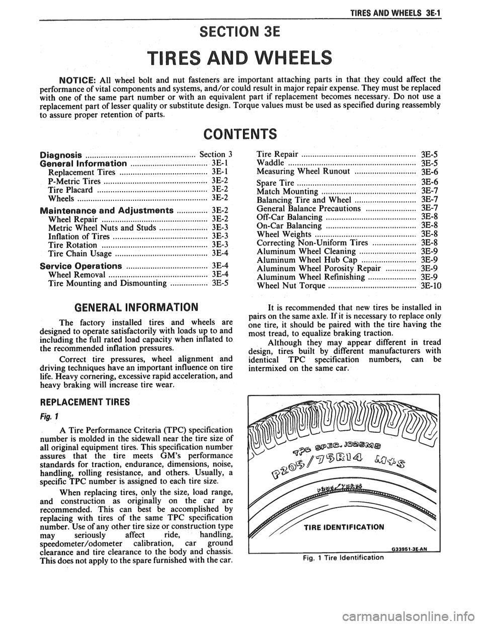
Fig. 1
A Tire Performance Criteria (TPC) specification
number is molded in the sidewall near the tire size of
all original equipment tires. This specification number
assures that the tire meets
GM's performance
standards for traction, endurance, dimensions, noise,
handling, rolling resistance, and others. Usually, a
specific TPC number is assigned to each tire size.
When replacing tires, only the size, load range,
and construction as originally on the car are
recommended. This can best be accomplished by
replacing with tires of the same TPC specification
number. Use of any other tire size or construction type
may seriously affect ride, handling,
speedometer/odometer calibration, car ground
clearance and tire clearance to the body and chassis.
This does not apply to the spare furnished with the car.
v// TIRE IDENTIFICATION
Fig. 1 Tire Identification
Page 233 of 1825
3E.2 TIRES AND WHEELS
P-METRIC SIZED TIRES
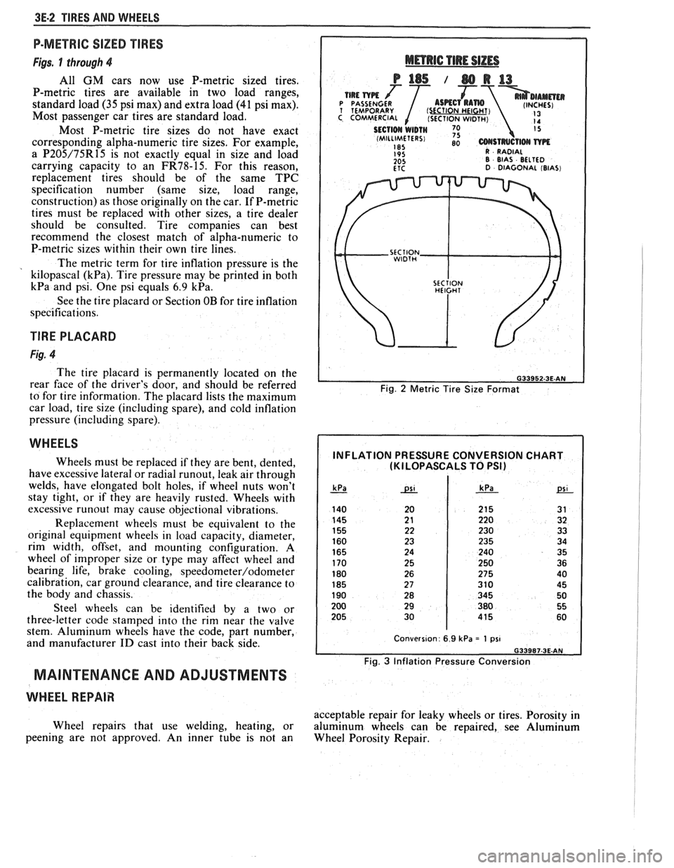
Figs. 1 through 4
All GM cars now use P-metric sized tires.
P-metric tires are available in two load ranges,
standard load
(35 psi max) and extra load (41 psi max).
Most passenger car tires are standard load.
Most P-metric tire sizes do not have exact
corresponding alpha-numeric tire sizes. For example,
a
P205/75R15 is not exactly equal in size and load
carrying capacity to an
FR78-15. For this reason,
replacement tires should be of the same TPC
specification number (same size, load range,
construction) as those originally on the car. If P-metric
tires must be replaced with other sizes, a tire dealer
should be consulted. Tire companies can best
recommend the closest match of alpha-numeric to
P-metric sizes within their own tire lines.
The metric term for tire inflation pressure is the
kilopascal
(kPa). Tire pressure may be printed in both
kPa and psi. One psi equals 6.9 kPa.
See the tire placard or Section OB for tire inflation
specifications.
TlRE PLACARD
Fig. 4
The tire placard is permanently located on the
rear
face of the driver's door, and should be referred
to for tire information. The placard lists the maximum
car load, tire size (including spare), and cold inflation
pressure (including spare).
WHEELS
Wheels must be replaced if they are bent, dented,
have excessive lateral or radial
runout, leak air through
welds, have elongated bolt holes, if wheel nuts won't
stay tight, or if they are heavily rusted. Wheels with
excessive
runout may cause objectional vibrations.
Replacement wheels must be equivalent to the
original equipment wheels in load capacity, diameter,
rim width, offset, and mounting configuration.
A
wheel of improper size or type may affect wheel and
bearing life, brake cooling,
speedometer/odometer
calibration, car ground clearance, and tire clearance to
the body and chassis.
Steel wheels can be identified by a two or
three-letter code stamped into the rim near the valve
stem. Aluminum wheels have the code, part number,
and manufacturer
ID cast into their back side.
MAINTENANCE AND ADJUSTMENTS
WHEEL REPAIR
Wheel repairs that use welding, heating, or
peening are not approved. An inner tube is not an
Fig. 2 Metric Tire Size Format
INFLATION PRESSURE CONVERSION CHART (KI LOPASCALS TO PSI)
Fig. 3 Inflation Pressure Conversion
acceptable repair for leaky wheels or tires. Porosity in
aluminum wheels can be repaired, see Aluminum
Wheel Porosity Repair.