1988 PONTIAC FIERO run flat
[x] Cancel search: run flatPage 309 of 1825
5-16 BRAKES
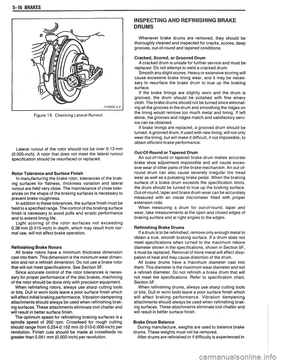
Figure 15 Checking Lateral Runout
Lateral runout of the rotor should not be over 0.13 mm
(0.005-inch). A rotor that does not meet the lateral runout
specification should be resurfaced or replaced.
Rotor Tolerance and Surface Finish
In manufacturing the brake rotor, tolerances of the brak-
ing surfaces for flatness, thickness variation and lateral
runout are held very close. The maintenance of close toler-
ances on the shape of the braking surfaces is necessary to
prevent brake roughness. In addition to these tolerances, the surface finish must be
held to a specified range. The control of the braking surface
finish is necessary to avoid pulls and erratic performance
and to extend lining life.
Light scoring of the rotor surfaces not exceeding
0.38
mrn (0.015-inch) in depth, which may result from nor-
mal use, will not affect brake operation.
Refinishing Brake Rotors
All brake rotors have a minimum thickness dimension
cast into them. This dimension is the minimum wear dimen-
sion and not a refinish dimension. Do not use a brake rotor
that will not meet specifications. See Section
5F.
Since accurate control of the rotor tolerances is neces-
sary for proper performance of the disc brakes, machining
of the rotor should be done only with precision equipment.
When refinishing rotors, always use sharp cutting tools
or bits. Dull or worn tools leave a poor surface finish which
will affect initial braking performance. Vibration dampening
attachments should always be used when refinishing brak-
ing surfaces. These attachments eliminate tool chatter and
will result in better surface finish.
The optimum speed for refinishing braking surfaces is a
spindle speed of 200 rpm. Crossfeed for rough cutting
should range from 0.254-0.152 mm (0.010-0.006-inch) per
revolution. Finish cuts should be made at crossfeeds no
greater than 0.051 mm (0.002-inch) per revolution.
INSPECTING AND REFlNlSHlMG BRAKE
DRUMS
Whenever brake drums are removed, they should be
thoroughly cleaned and inspected for cracks, scores, deep
grooves, out-of-round and tapered conditions.
Cracked, Scored, or Grooved Drum
A cracked drum is unsafe for further service and must be
replaced. Do not attempt to weld a cracked drum.
Smooth any slight scores. Heavy or extensive scoring will
cause excessive brake lining wear, and it may be neces-
sary to resurface the brake drum to true up the braking
surface.
If the brake linings are slightly worn and the drum is
grooved, the drum should be polished with fine emery
cloth. The brake drums should not be turned since eliminat-
ing all the grooves in the drum and smoothing the ridges on
the lining would remove too much metal and lining. If left
alone, the grooves and ridges match and satisfactory serv-
ice can be obtained. If brake linings are replaced, a grooved drum should be
turned. Agrooved drum, if used with new lining, will not only
wear the lining, but will make it difficult, if not impossible, to
obtain efficient brake performance.
But-Of-Round or Tapered Drum
An out-of-round or tapered brake drum makes accurate
brake shoe adjustment impossible and will cause exces-
sive wear of other parts of the brake mechanism. An out-of-
round drum can also cause severely irregular tire tread
wear as well as a pulsating brake pedal. When the braking
surface of a brake drum exceeds the specification limits,
the drum should be turned to true up the braking surface.
Out-of-round, taper and brake drum wear can be accurately
measured with an inside micrometer fitted with proper
extension rods. When measuring a drum for out-of-round, taper and
wear, take measurements at the open and closed edges of
braking surface and at right angles to the edges.
Refinishing Brake Drums
If adrum is to be refinished, remove only enough metal to
obtain a true, smooth braking surface. If a drum does not
meet specifications when turned to the maximum
rebore
diameter shown in the specifications, shown in Section 5F,
it must be replaced. Removal of more metal will affect dissi-
pation of heat and may cause distortion of the drum.
All brake drums have a maximum diameter cast into
them. This diameter is the maximum wear diameter and not
a refinish diameter. Do not refinish a brake drum that will
not meet the specifications. Refer to specification chart,
Section 5F. When refinishing drums, always use sharp cutting tools
or bits. Dull or worn tools leave a poor surface finish which
will affect braking performance. Vibration dampening
attachments should always be used when refinishing brak-
ing surfaces. These attachments eliminate tool chatter and
will result in better surface finish.
Brake Drum Balance
During manufacture, weights are used to balance brake
drums. These weights must not be removed.
After drums are refinished or if difficulty is experienced in
Page 363 of 1825
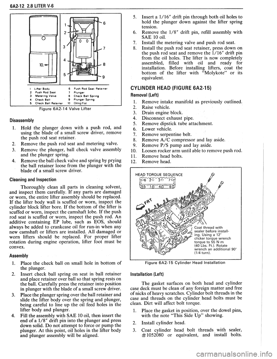
I Liher Body 6 Push Rod Seat Reta~ner 2 Push Rod Seal 7 Plunger 3 Mater~ng Valve 8 Check Ball Spr~ng 4 Check Ball 9 Plunger Spr~ng 5 Check Ball Rete~ner 10 Olllna Flat
Figure 6A2-14 Valve Lifter
Disassembly
1. Hold the plunger down with a push rod, and
using the blade of a small screw driver, remove
the push rod seat retainer.
2. Remove the push rod seat and metering valve.
3. Remove the plunger, ball check valve assembly
and the plunger spring.
4. Remove the ball check valve and spring by prying
the ball retainer loose from the plunger with the
blade of a small screw driver.
Cleaning and Inspection
Thoroughly clean all parts in cleaning solvent,
and inspect them carefully. If any parts are damaged
or worn, the entire lifter assembly should be replaced.
If the lifter body wall is scuffed or worn, inspect the
cylinder block lifter bore. If the bottom of the lifter is
scuffed or worn, inspect the camshaft lobe. If the push
rod seat is scuffed or worn, inspect the push rod. An
additive containing EP lube, such as EOS, should
always be added to crankcase oil for run-in when any
new camshaft or lifters are installed. All damaged or
worn lifters should be replaced. For proper lifter
rotation during engine operation, lifter foot must be
convex.
Assembly
1. Place
the check ball on small hole in bottom of
the plunger.
2. Insert
check ball spring on seat in ball retainer
and place retainer over ball so that spring rests on
the ball. Carefully press the retainer into position
in plunger with the blade of a small screw driver.
3. Place the plunger spring over the ball retainer and
slide the lifter body over the spring and plunger,
being careful to line up the oil feed holes in the
lifter body and plunger.
4. Fill the assembly with SAE 10 oil, then insert the
end of a
1/8" drift pin into the plunger and press
down solid. Do not attempt to force or pump the
plunger. At this point, oil holes in the lifter body
and plunger assembly will be aligned.
5. Insert a 1/16" drift pin through both oil holes to
hold the plunger down against the lifter spring
tension.
6. Remove
the
1/8" drift pin, refill assembly with
SAE 10 oil.
7. Install the metering valve and push rod seat.
8. Install the push rod seat retainer, press down on
the push rod seat and remove the 1/16" drift pin
from the oil holes. The lifter is now completely
assembled, filled with oil and ready for
installation. Before installing lifters, coat the
bottom of the lifter with "Molykote" or its
equivalent.
CYLINDER HEAD (FIGURE 6A2-15)
Removal (Left)
Remove intake manifold as previously outlined.
Raise vehicle.
Drain engine block.
Disconnect exhaust pipe.
Remove dipstick tube attachment.
Lower vehicle.
Remove serpentine belt.
Remove A/C compressor and lay aside.
Remove
P/S pump and lay aside.
Loosen rocker arm until able to remove push rod.
Remove head bolts.
Remove head.
HEAD TORQUE SEQUENCE
/7 , 2 ing. Using a 12"
Figure 6A2-1'5 Cylinder Head Installation
Installation (Left)
The gasket surfaces on both head and cylinder
case deck must be clean of any foreign matter and free
of nicks of heavy scratches. Cylinder bolt threads in the
case and threads on the cylinder head bolts must be
clean. Dirt will affect bolt torque.
1. Place the gasket in position, over the dowel pins,
with the note "This Side Up" showing.
2. Install cylinder head.
3. Coat cylinder head bolt threads with sealer,
#1052080 or equivalent, and install bolts.
Page 389 of 1825
QA3-10 V-8 ENGINE
lnstallation
1. Install valve stem seal over valve stem and seat
against head.
2. Set
the valve spring and damper, oil shedder and
valve cap in place. Compress the spring with Tool
J-5892 and install oil seal in the lower groove of
the stem, making sure the seal is flat and not
twisted. A light coat of oil on the seal will help
prevent twisting.
3. Install
the valve locks and release the compressor
tool making sure the locks seat properly in the
upper groove of the valve stem. Grease may be
used to hold the locks in place while releasing the
compressor tool.
4. Using tool J-23994, apply vacuum to the valve
cap to make sure no air leaks past the seal.
5. Install spark plug and torque to 22 lb. ft.
(30N.m).
6. Install and adjust valve mechanism as previously
outlined.
VALVE LIFTERS
Hydraulic valve lifters very seldom require
attention. The lifters are extremely simple in design,
readjustments are not necessary, and servicing of the
lifters requires only that care and cleanliness be
exercised in the handling of parts.
Valve Lifter Diagnosis
1.
Momentarily Noisy When Car is Started:
This condition is normal. Oil drains from the
lifters which are holding the valves open when the
engine is not running. It will take a few seconds
for the lifter to fill after the engine is started.
2. Intermittently Noisy On Idle Only. Disappearing
When Engine Speed is Increased:
Intermittent clicking may be an indication of a
pitted check valve ball, or it may be caused by
dirt.
Correction: Clean the lifter and inspect. If check
valve ball is defective, replace lifter.
3. Noisy At Slow Idle Or With Hot Oil, Quiet With
Cold Oil Or As Engine Speed Is Increased:
High leak down rate. Replace suspect lifter.
4. Noisy At High Car Speeds And Quiet At Low
Speeds:
a. High oil level
- Oil level above the "Full"
mark allows crankshaft counterweights to
churn the oil into foam. When foam is
pumped into the lifters, they will become
noisy since a solid column of oil is required
for proper operation. Correction: Drain oil
inti1 proper level is obtained.
b. Low oil level - Oil level below the "Add"
mark allows the pump to pump air at high
speeds which results in noisy lifters.
Correction: Fill until proper oil level is
obtained.
c. Oil pan bent on bottom or pump screen
cocked or loose, replace or repair as
necessary. 5.
Noisy At Idle Becoming Louder As Engine Speed
Is Increased To 1500 rpm:
This noise is not connected with lifter
malfunction. It becomes most noticeable in the
car at 10 to 15 mph "1" (Low) range, or 30 to
35
mph "DM (Drive) range and is best described as
a
hashy sound. At slow idle, it may be entirely
gone or appear as a light ticking noise in one or
more valves. It is caused by one or more of the
following:
a. Badly worn or scuffed valve tip and rocker
arm pad.
b. Excessive valve stem to guide clearance.
c. Excessive valve seat
runout.
d. Off square valve spring.
e. Excessive valve face
runout.
f. Valve spring damper clicking on rotator.
Removal
1.
Remove intake manifold as previously outlined.
2. Remove valve mechanism as previously outlined.
3. Remove valve lifter retainer.
4. Remvoe valve lifter restrictor.
5. Remove valve lifters (Fig.
6A3-7). Place valve
lifters in a rack so that they may be reinstalled in
the same location.
Installation
1.
Coat roller of valve lifters with "Molykote" or its
equivalent and install valve lifters.
2. Install valve lifter restrictor.
3. Install valve lifter retainer.
4. Install intake manifold as previously outlined.
5. Install and adjust valve mechanism as outlined.
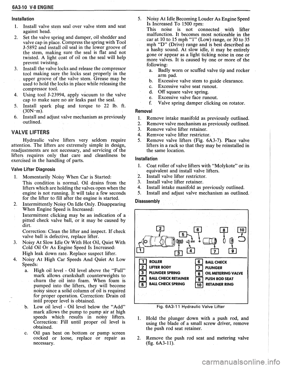
Disassembly
PLUNGER SPRING
Fig. 6A3-1 1 Hydraulic Valve Lifter
1. Hold the plunger down with a push rod, and
using the blade of a small screw driver, remove
the push rod seat retainer.
2. Remove the push rod seat and metering valve
(fig.
6A3- 1 1).
Page 435 of 1825

6C-4 ENGINE FUEL
to fully insert the unleaded gas nozzle will result in
gasoline splashing back out of the filler neck.
Fuel Gage Sending Unit
The fuel gage sending unit is attached to the top
of the fuel tank. It is held in place with a cam lock ring
and a gasket is used between the tank and sending unit.
Sending units have three hoses attached. One line
is for the fuel feed. The second line is connected to the
vapor canister, to keep fuel vapor from getting into the
air (see Section 6E). The third line is used as a fuel
return line to the tank.
On some sending units a wire is attached to the
unit. On others the connectors attach directly to the
sender.
When a fuel gage sending unit is removed always
make sure to install the gasket and any power or
ground leads that were removed.
DIAGNOSIS
Fuel system diagnostic procedures are located in
Section(s) 6E1 thru 6E3.
SERVICE PROCEDURES
If the fuel system is suspected of delivering an
improper amount of fuel, it should be inspected and
tested in the vehicle, as follows:
1. Make certain that there is fuel in the tank.
2. With the engine running, inspect for leaks at all
fuel feed pipe and hose connections from
fuel
tank to injection pump. Tighten any loose
connections. Inspect all hoses for flattening or
kinks which would restrict the flow of fuel. Air
leaks or restrictions on suction side of fuel pump
will seriously affect pump output.
FUEL SYSTEM PRESSURE RELIEF
CAUTION: To reduce risk of fire and
personal injury, it is necessary to
relieve duel system pressure before
servicing fuel system components. To
do this:
Remove "fuel pump" fuse from fuse
block in passenger compartment.
e Crank engine - engine will start and run
until fuel supply remaining in fuel lines is
consumed. Engage starter for
3.0
seconds to assure relief of any remaining
pressure.
e With ignition "OFF", replace duel pump
fuse.
Unless this procedure
is followed before
servicing fuel lines
or connections, fuel
spray could occur.
When repair to the fuel system has been
completed, start engine and check all connections that
were loosened for possible leaks.
Refer to Section 6E for additional diagnosis of
engine fuel system.
Fuel Pump Flow Test
1. Test fuel
pump by connecting hose from EFI fuel
feed line to a suitable unbreakable container.
Apply battery voltage to the fuel pump test
terminal (terminal
"G" of ALCL).
2. Fuel pump should supply
1/2 pint or more in 15
seconds.
3. If flow is below minimum, check for fuel
restriction. If there is no restriction, check pump
pressure.
Fuel System Pressure Test
This test must be performed when diagnosing the
fuel system.
CAUTION: To reduce the risk of fire
and personal injury, it is necessary to
relieve fuel system pressure before
servicing fuel system components on
the
TBI system. To do this:
s Remove "Fuel Pump" fuse from fuse block in
passenger compartment.
e Crank engine. Engine will start and run until fuel
remaining in fuel lines is consumed. Crank the
starter for three seconds to assure that any
remaining pressure is relieved.
e With the ignition off, replace the "Fuel Pump"
fuse.
1. Obtain two
sections of
3/8" steel tubing. Each
should be about 254 mm (10 inches) long.
I
Double-flare one end of each section.
2. Install a flare nut on each section. Connect each i
of the above sections of tubing into the "flare nut 1
to flare nut adapters" that are included in J-29658 i
Gage Adapters.
3. Attach the
pipe and adapter assemblies to the
J-29658 gage.
4. Hoist the car.
5. Disconnect
front fuel feed hose from the fuel pipe
on the body.
1
6. Install a
254 mm (10 inch) length of 3/8" fuel
hose onto the fuel feed pipe on the body. Attach 1
I the other end of the hose onto one of the sections
of pipe mentioned in Step 1. Secure the hose
connections with clamps.
7. Attach the front fuel feed hose onto the other
i
section of tubing mentioned in Step 1. Secure the I
hose connection with a clamp. I
8. Start
the engine and check for leaks. I 9. Observe
the fuel pressure reading. It should be 62
to 90
kPa (9 to 13 psi). If not, refer to the I
appropriate Emissions Section.
10. Depressurize
the fuel system and remove the gage I
with adapters. Reconnect the fuel feed hose to the
pipe and torque the clamp to
1.7 N.m (1 5 lb. in.).
11. Lower
the car. Start the engine and check for fuel
leaks.
Fuel System Pressure Test- MPFl
Fuel system diagnosis is in Section 6E3, Chart
A-7.
Page 1081 of 1825
700-R4-30 AUTOMATIC TRANSMISSION
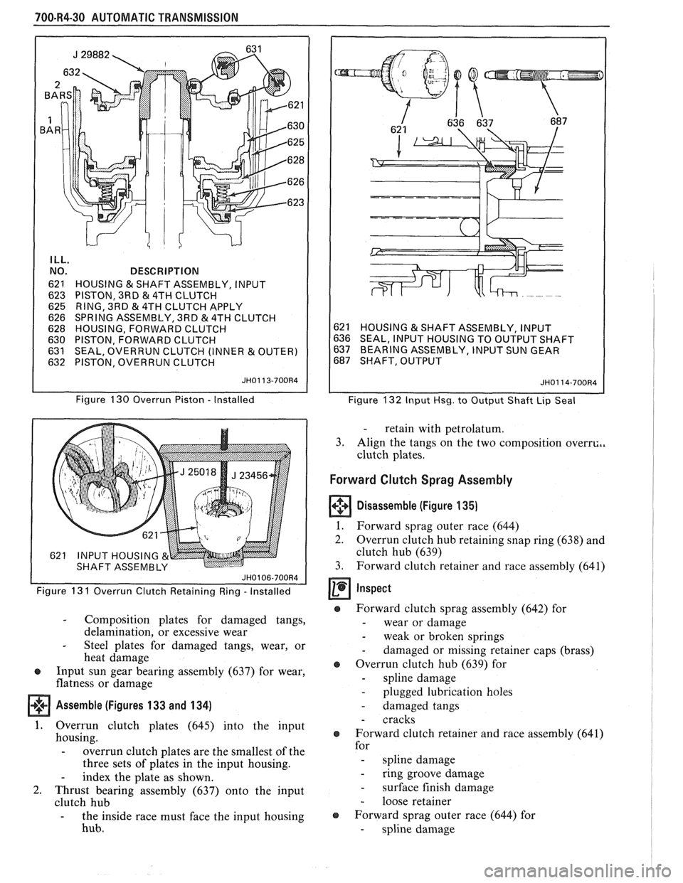
ILL.
NO.
62
1
623 625
626
628
630
63
1 632 DESCRIPTION
HOUSING
& SHAFT ASSEMBLY, INPUT
PISTON, 3RD
& 4TH CLUTCH
RING, 3RD
81 4TH CLUTCH APPLY
SPRING ASSEMBLY, 3RD & 4TH CLUTCH
HOUSING, FORWARD CLUTCH
PISTON, FORWARD CLUTCH
SEAL, OVERRUN CLUTCH (INNER
& OUTER)
PISTON, OVERRUN CLUTCH
JH0113-700R4
Figure 130 Overrun Piston - Installed
Figure 13
1 Overrun Clutch Retaining Ring - Installed
- Composition plates for damaged tangs,
delamination, or excessive wear
- Steel plates for damaged tangs, wear, or
heat damage
@ Input sun gear bearing assembly (637) for wear,
flatness or damage
Assemble (Figures 133 and 134)
1. Overrun clutch plates (645) into the input
housing.
- overrun clutch plates are the smallest of the
three sets of plates in the input housing.
- index the plate as shown.
2. Thrust bearing assembly (637) onto the input
clutch hub
- the inside race must face the input housing
hub.
621 HOUSING & SHAFT ASSEMBLY, INPUT
636 SEAL, INPUT HOUSING TO OUTPUT SHAFT
637 BEARING ASSEMBLY, INPUT SUN GEAR
687 SHAFT, OUTPUT
JH0114-700R4
Figure 132 Input Hsg. to Output Shaft Lip Seal
- retain with petrolatum.
3. Align the tangs on the two composition
overrc.,
clutch plates.
Forward Clutch Sprag Assembly
Disassemble (Figure 135)
1.
Forward sprag outer race (644)
2. Overrun clutch hub retaining snap ring (638) and
clutch hub (639)
3. Forward clutch retainer and race assembly (641)
Inspect
@ Forward clutch sprag assembly (642) for
- wear or damage
- weak or broken springs
- damaged or missing retainer caps (brass)
@ Overrun clutch hub (639) for
- spline damage
- plugged lubrication holes
- damaged tangs
- cracks
o Forward clutch retainer and race assembly (641)
for
- spline damage
- ring groove damage
- surface finish damage
- loose retainer
o Forward sprag outer race (644) for
- spline damage
Page 1083 of 1825
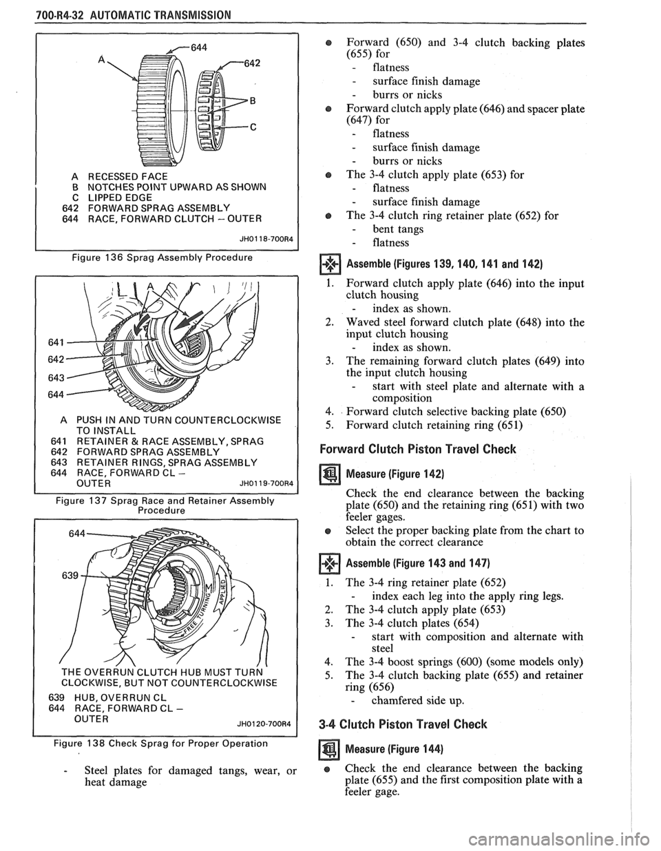
700-R4-32 AUTOMATIC TRANSMISSION
A RECESSED FACE
B NOTCHES POINT UPWARD AS SHOWN
C LIPPED EDGE
642 FORWARD SPRAG ASSEMBLY
644 RACE, FORWARD CLUTCH
- OUTER
Figure 136 Sprag Assembly Procedure
COUNTERCLOCKWISE
641
RETAlNER&RACEASSEMBLY,SPRAG 642 FORWARD SPRAG ASSEMBLY
INER RINGS, SPRAG ASSEMBLY
FORWARD CL -
Figure 137 Sprag Race and Retainer Assembly
Procedure
THE OVERRUN'CLUTCH HUB MUST TURN '
I CLOCKWISE, BUT NOT COUNTERCLOCKWISE I
639 HUB, OVERRUN CL
644 RACE, FORWARD CL - OUTER JH0120-700R4
Figure 138 Check Sprag for Proper Operation
- Steel plates for damaged tangs, wear, or
heat damage
e Forward (650) and 3-4 clutch backing plates
(655) for
- flatness
- surface finish damage
- burrs or nicks
Forward clutch apply plate (646) and spacer plate
(647) for
- flatness
- surface finish damage
- burrs or nicks
@ The 3-4 clutch apply plate (653) for
- flatness
- surface finish damage
o The 3-4 clutch ring retainer plate (652) for
- bent tangs
- flatness
Assemble (Figures 139, 140, 141 and 142)
1. Forward clutch apply plate (646) into the input
clutch housing
- index as shown.
2. Waved steel forward clutch plate (648) into the
input clutch housing
- index as shown.
3. The
remaining forward clutch plates (649) into
the input clutch housing
- start with steel plate and alternate with a
composition
4. Forward clutch selective backing plate (650)
5. Forward clutch retaining ring (651)
Forward Clutch Piston Travel Check
Measure (Figure 142)
Check the end clearance between the backing
plate (650) and the retaining ring (65 1) with two
feeler gages.
Select the proper backing plate from the chart to
obtain the correct clearance
Assemble (Figure 143 and 147)
1. The 3-4 ring retainer plate (652)
- index each leg into the apply ring legs.
2. The 3-4 clutch apply plate (653)
3. The
3-4 clutch plates (654)
- start with composition and alternate with
steel
4. The 3-4 boost springs (600) (some models only)
5. The
3-4 clutch backing plate (655) and retainer
ring (656)
- chamfered side up.
3-4 Clutch Piston Travel Check
Measure (Figure 144)
e Check the end clearance between the backing
plate (655) and the first composition plate with
a
feeler gage.
Page 1535 of 1825
LUMBAR AND BOLSTER SUPPORT
TROUBLESHOOTING HINTS
@ Try the follovving checks before doing the
System Check.
1. Check the In-Line Fuse.
2. Check the PWR ACC Circuit Breaker.
COMPONENT LOCATION
Fuse Block. ..................... Behind LN side of IIP, below light switch.
In-Line Fuse Holder
.............. Taped to 6331, below LR front seat
Lumbar
PumpIMotor ............. Underside of LN front side
Lumbar
PumpIMotor Relay. ....... Underside of LN front seat Page-Figure
201-10-A
3. If the Lumbar
PumpIMotor runs, but both
Lumbar Valve Assembly .......... Underside of respective front seat
driver's and passenger's Lumbar and Bolster
C238 (12 cavities) ................ LN shroud, ahead of center access hole. ........ 201-11-C
Supports do not operate, check the
contin& C330 (2 cavities) ................. Underside of LM front seat
to ground of
BLKIWNT (769) wire (see C331(4 cavities) ................. Underside of LN front seat
schematic). C332 (4 cavities)
................. Underside of RH front seat
.......................... 4. Check the hose between the Valve Assemblies 6216
At
LH shroud
.......................... ............... and the PumpIMotor for leaks or cracks. S233. IIP harness, above Fuse Block. 201-10-A
.......................... r Go to System Check for a guide to normal S331. Lumbar harness, below LR front seat
.......................... operation. S332. Lumbar harness, below LR front seat
S333. .......................... Lumbar harness, below LH front seat r Go to System Diagnosis for diagnostic tests. S334. .......................... Lumbar harness, below LN front seat
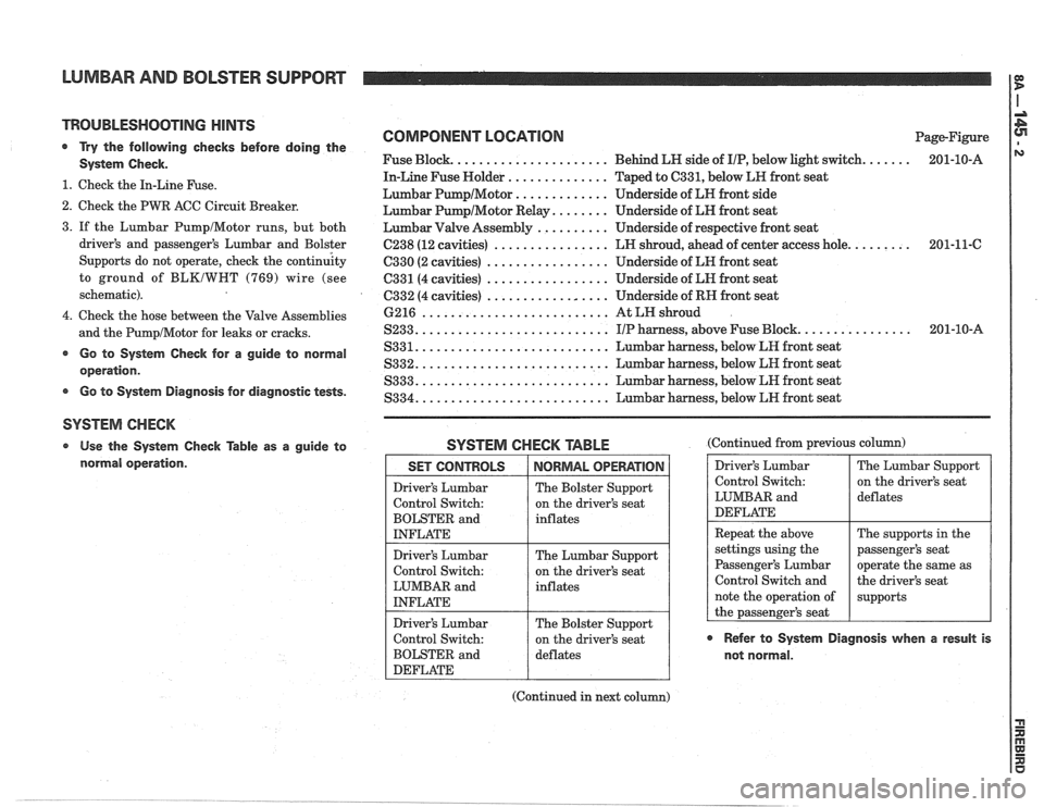
SYSTEM CHECK
Use the System Check Table as a guide to SYSTEM CHECK TABLE (Continued from previous col
normal operation. Driver's Lumbar
Control Switch:
LUMBAR and
DEFLATE
Repeat the above
settings using the
Passenger's Lumbar
Control Switch and
note the operation of
the passenger's seat
@ Refer to System Diagnosis when a result is
not normal.
The Lumbar Support
on the driver's seat
deflates
The supports in the
passenger's seat
operate the same as
the driver's seat
supports SET CONTROLS
Driver's Lumbar
Control Switch:
BOLSTER and
INFLATE
Driver's Lumbar
Control Switch:
LUMBAR and
INFLATE
Driver's Lumbar
Control Switch:
BOLSTER and
DEFLATE
(Continued in next column)
NORMAL OPERATION
The Bolster Support
on the driver's seat
inflates
The Lumbar Support
on the driver's seat
inflates
The Bolster Support
on the driver's seat
deflates
Page 1702 of 1825
STATIONARY GLASS - F STYLE 2H-5
1 1.
Install windshield reveal molding.
12. Install all other previously removed parts and
clean up.
13. On windshield installations, car must remain at
normal room temperature for six hours to
complete proper cure of adhesive material.
WATERLEAK CORRECTION
Urethane glass installation waterleaks can be
corrected without removing and reinstalling glass
where accessible. This method applies only with use of
adhesive furnished in kit no. 9636067 or equivalent.
1. Remove reveal moldings in area of leak. In some
cases, it may become necessary to remove garnish
moldings or finishing lace to locate source of leak.
2. Mark location of
leak(s). Carefully push outward
on glass in area of leak to determine extent of
leak. This operation should be performed while
water is being applied to leak area. Mark extent
of leak area.
@ Clean
From outside body, clean any dirt or foreign
material from leak area with water; then dry area
with air hose.
3. Using a sharp knife, trim off uneven edge of
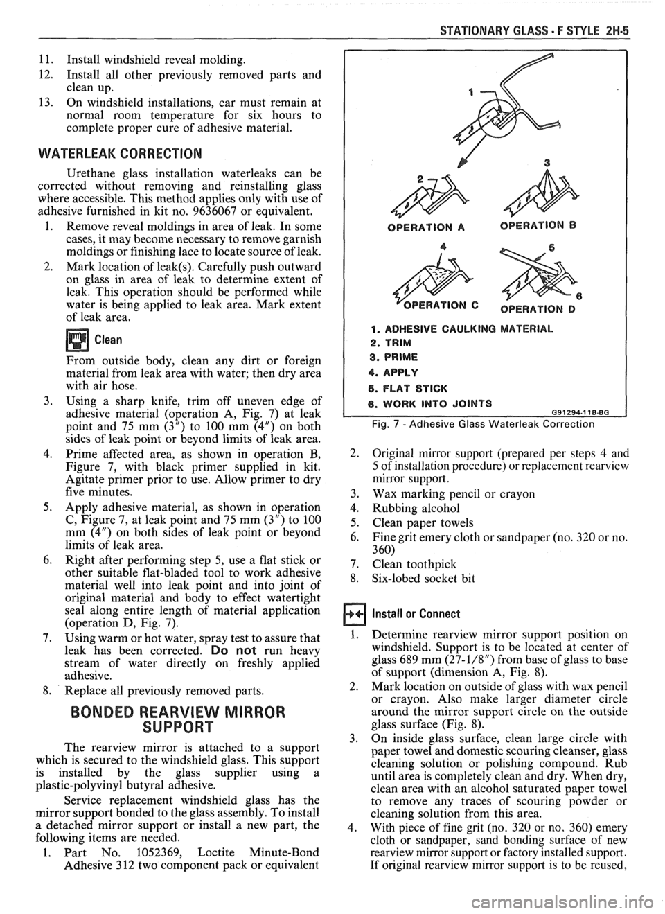
adhesive material (operation A, Fig. 7) at leak
point and 75 mm
(3") to 100 mm (4") on both
sides of leak point or beyond limits of leak area.
4. Prime affected area, as-shown in operation B,
Figure 7, with black primer supplied in kit.
Agitate primer prior to use. Allow primer to dry
five minutes.
5. Apply adhesive material, as shown in operation
C, Figure 7, at leak point and 75 mm (3") to 100
mm (4") on both sides of leak point or beyond
limits of leak area.
6. Right after performing step 5, use a flat stick or
other suitable flat-bladed tool to work adhesive
material well into leak point and into joint of
original material and body to effect watertight
seal along entire length of material application
(operation D, Fig. 7).
7. Using warm or hot water, spray test to assure that
leak has been corrected.
Do not run heavy
stream of water directly on freshly applied
adhesive.
8. Replace all previously removed parts.
BONDED REARVIEW MIRROR
SUPPORT
The rearview mirror is attached to a support
which is secured to the windshield glass. This support
is installed by the glass supplier using a
plastic-polyvinyl butyral adhesive.
Service replacement windshield glass has the
mirror support bonded to the glass assembly. To install
a detached mirror support or install a new part, the
following items are needed.
1. Part No. 1052369, Loctite Minute-Bond
Adhesive 3 12 two component pack or equivalent
OPERATION A OPERATION B
OPERATION D
1. ADHESIVE CAULKING MATERIAL
2. TRIM
3. PRIME
4. APPLY
6. FLAT STICK
6. WORK INTO JOINTS 691294.1 18-BG
Fig. 7 - Adhesive Glass Waterleak Correction
2. Original mirror support (prepared per steps 4 and
5 of installation procedure) or replacement rearview
mirror support.
3. Wax marking pencil or crayon
4. Rubbing alcohol
5. Clean paper towels
6. Fine grit emery cloth or sandpaper (no. 320 or no.
3 60)
7. Clean toothpick
8. Six-lobed socket bit
Install or Connect
1. Determine rearview mirror support position on
windshield. Support is to be located at center of
glass 689 mm
(27-1/8") from base of glass to base
of support (dimension A, Fig.
8).
2. Mark location on outside of glass with wax pencil
or crayon. Also make larger diameter circle
around the mirror support circle on the outside
glass surface (Fig. 8).
3. On
inside glass surface, clean large circle with
paper towel and domestic scouring cleanser, glass
cleaning solution or polishing compound. Rub
until area is completely clean and dry. When dry,
clean area with an alcohol saturated paper towel
to remove any traces of scouring powder or
cleaning solution from this area.
4. With piece of fine grit (no. 320 or no. 360) emery
cloth or sandpaper, sand bonding surface of new
rearview mirror support or factory installed support.
If original
rearview mirror support is to be reused,