Page 229 of 346
ENGINE MECHANICAL - Cylinder Block
EM-67
15. REMOVE OIL PUMP DRIVE SHAFT
(a)
Remove the bolt and oil pump drive shaft.
(b) While turning oil pump drive shaft, slowly pull out so
as not to damage the bearing.
16. REMOVE OIL PUMP /
(a) Loosen the union nut.
(b)
Remove the two bolts and oil pump.
17. REMOVE REAR OIL SEAL RETAINER
Remove the five bolts, rear oil seal retainer and gasket.
18. CHECK CONNECTING ROD THRUST CLEARANCE
Using a dial indicator, measure the thrust clearance while
moving the rod back and forth.
Standard thrust clearance:
0.160 - 0.296 mm
(0.0063 - .0.0117 in.)
Maximum thrust clearance:
0.3 mm (0.012 in.)
If clearance is greater than maximum, replace the connect-
ing rod assembly. If necessary, replace the crankshaft.
19. REMOVE CONNECTING ROD CAPS AND CHECK OIL
CLEARANCE
Ia) Using a punch or numbering stamp, place the
matchmarks on the rod and cap to ensure correct
reassembly.
Page 232 of 346
EM-70 ENGINE MECHANICAL - Cylinder Block
c Front
1 2 3 4 5 6
EM147: 3
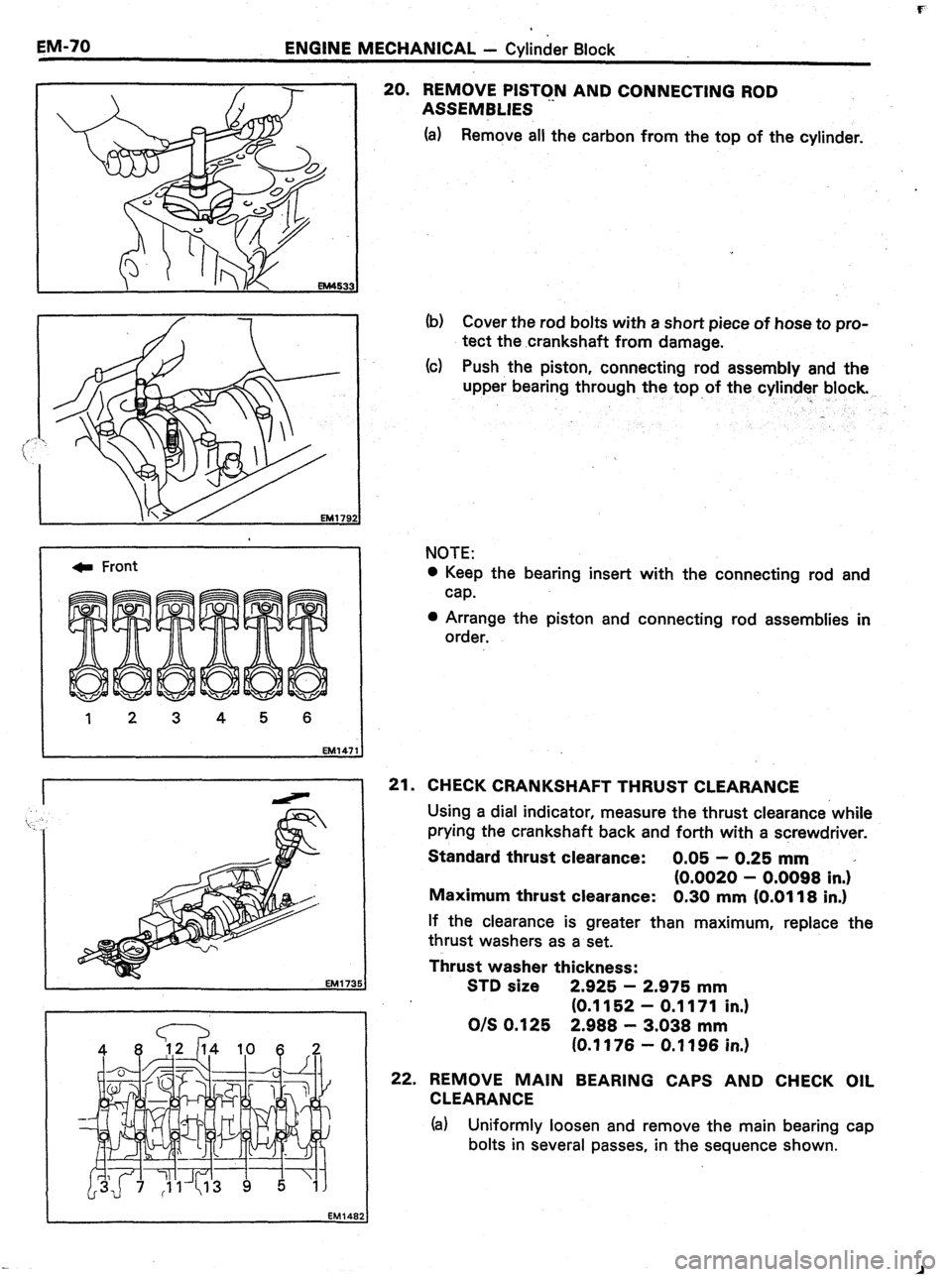
20. REMOVE PISTON AND CONNECTING ROD
ASSEMBLIES
(a) Remove all the carbon from the top of the cylinder.
(b) Cover the rod bolts with a short piece of hose to pro-
tect the crankshaft from damage.
(c) Push the piston, connecting rod assembly and the
upper bearing through the top of the cylinder block.
NOTE:
0 Keep the bearing insert with the connecting rod and
cap.
l Arrange the piston and connecting rod assemblies in
order.
21. CHECK CRANKSHAFT THRUST CLEARANCE
Using a dial indicator, measure the thrust clearance while
prying the crankshaft back and forth with a screwdriver.
Standard thrust clearance: 0.05 - 0.25 mm
(0.0020 - 0.0098 in.)*
Maximum thrust clearance: 0.30 mm (0.0118 in.)
If the clearance is greater than maximum, replace the
thrust washers as a set.
Thrust washer thickness:
STD size 2.925 - 2.975 mm
(0.1152 - 0.1171 in.)
O/S 0.125 2.988 - 3.038 mm
(0.1176 - 0.1196 in.)
22. REMOVE MAIN BEARING CAPS AND CHECK OIL
CLEARANCE
(a) Uniformly loosen and remove the main bearing cap
bolts in several passes, in the sequence shown.
Page 233 of 346
ENGINE MECHANICAL Y Cylinder Block-
. . ,., ,,
..“./.. E”Q+‘J.g
. . . “h,. ,<_ .,., aa* _
. . . . . . . ..I. C/~ a....,,.?._.h, j
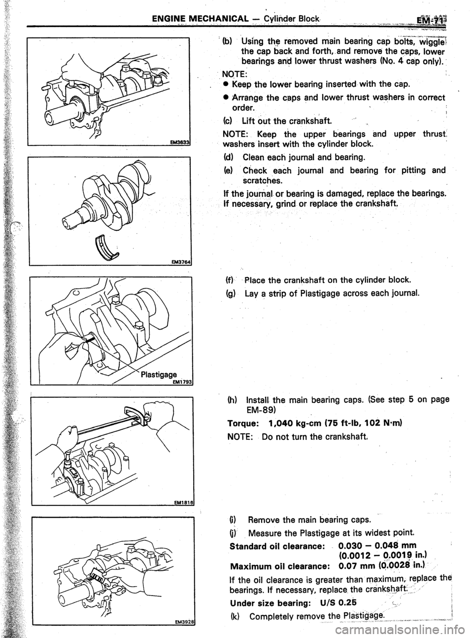
’ (b) Using the removed main bearing cap bo~t&?&gg~~
the cap back and forth,.and remove the caps, lower
bearings an! lower thrust washers (No. 4 cap only).
., NOTE: :
0 Keep the lower bearing inserted-with the cap.
0 Arrange the caps and lower thrust washers in correct
order.
9
(c) Lift out the crankshaft. “j ,
NOTE: Keep the upper bearings and upper thrust
washers insert with the cylinder block.
(d) Clean each journal and bearing.
(e) Check each journal and bearing for pitting and
scratches.
If the jounial.or bearing is damaged, replace the bearings.
If necessary, grind or replace the crankshaft,
(f)- Place the crankshaft on the cylinder block.
Cg) Lay a strip of Plastigage across each journal.
(h) Install the main bearing caps. (See step 5 on page
EM-891
Torque: 1,040 kg-&n (75 ft-lb, 102 N*m)
NOTE: Do not turn the crankshaft.
(i) Remove the main bearing caps.
(i) Measure the Plastigage at its widest point.
Standard oil clearance: . 0.030 - 0.048 mm
(0.0012 - q.0019 in.)
Maximum oil clearance: 0.07 mm ((i.0026’in.)
If the oil clearance is greater than maximum, replace the
bearings. If necessary, replace the crankshaft ,: .‘-
Under size bearing: U/S 0.25 :-.
(k) Completely remove the Plastigage. i
,^ -_ _ . j” ,,I, ,. .a”*+% -,..: :,.-__, ,-,--se. .j.z,.
Page 236 of 346
EN’GINE &lECHANlCAL - Cylinder Block
1 33
6. REMOVE CYLINDER RIDGES
If the wear is less than 0.2 mm (0.008 in.), use a ridge
reamer to machine the top of the cylinder.
DISASSEMBLY OF PISTON AND
CONNECTING. ROD ASSEMBLIES
(See page EM-65)
1. CHECK FIT BETWEEN PlSTdN AND PIN :
Try to move the piston back
and forth on the piston pin.
If any movement is felt, replace the piston and pin as a set.
2. REMOVE PISTON RINGS
(a) Using a piston ring expander, remove the compres-
sion rings.
(b) Remove the two side rails and oil ring expander by
hand.
NOTE: Arrange the rings in correct order.
3.
DISCONNECT CONNECTING ROD FROM PISTON
(a) Using needle-nose pliers, remove the snap rings from
the piston.
Page 239 of 346
ENGINE MECHANICAL -. Cylinder Block
E,M.+$ i
-.
:
:
. . .
. .
‘,’
‘.
:
t‘,
::
,c ;
‘:
:‘
::
;
. .
:
,i
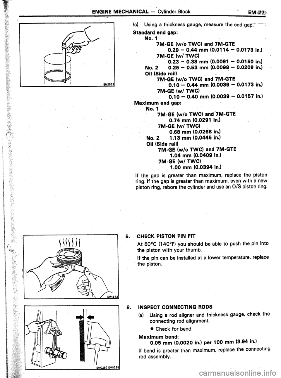
(c) Using a thickness gauge, measure the end ‘g&p,‘“--’ .‘:
.Standerd enb gap:
No. 1
7M-GE (w/o TWC) and 7M-GTE
0.29 - 0.44 mm (0.0114 - 0.0173 in.)
7M-GE (w/ TWC) .
0.23 - 0.38 mm (0.0091 - 0.0150 in.)
No. 2 0.25 - 0.53 mm (0.0098 - 0.0209 in.)
Oil (Side rail)
7M-GE (w/o TWC) and +M-GTE
0.10 -’ 0.44 mm (O.dO3g - 0.0173 in.)
7M-GE (w/ TWC)
0.10 - 0.40 mm (0.0039 - 0.0157 in.)
Maximum end gap:
No. 1
7M-GE (w/o T&Z) and ‘7M-GTE
0.74 mm (0.0291 in.)
7&l-GE (w/ TWC)
* 0.88 mm IO.0268 in.)
No. 2 1.13 mm (0.0445 in.)
Oil (Side rail)
7M-GE (w/o TWC) and 7M-GTE
1.04 mm (0.0409 in.)
7M-GE (w/ TWC)
1.00 mm (0.0394 in.)
If the gap is greater than maximum, replace the piston
ring.‘lf the gap is greater than maximum, even with a new
piston ring, rebore the cylinder and use an O/S piston ring.
5. CHECK PISTON PIN FIT
At 60°C (14OOF) you should be.able to push the pin into
the piston with your thumb.
If the pin can be installed at a lower temperature, replace
the piston.
8. INSPECT CONNECTING RODS
(a)
Using a rod aligner and thickness gauge, check the
connecting rod alignment.
0 Check for bend.
Maximum bend:
0.05 mm (0.0020 in.) per 100 mm (3.94 in.)
If bend is greater than maximum, replace the connecting
rod’ assembly.
Page 240 of 346
EM-78 ENGINE MECHANICAL - Cylinder Block
ml0269 EM029 OJ
EM0226
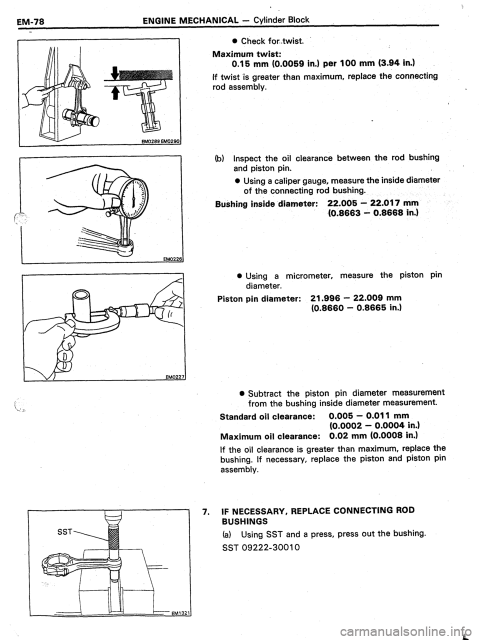
SST 0 Check fortwist.
Maximum twist:
0.15 mm (0.0059 in.) per 100 mm (3.94 in.)
If twist is greater than maximum, replace the connecting
rod assembly.
(b) Inspect the oil clearance between the rod bushing
and piston pin.
0 Using a caliper gauge, measure the inside diameter
of the connecting rod bushing.
BuShing inside diameter: 22.005 - 22.017 mm
IO.8663 - 0.8668 in.)
l Using a micrometer, measure the piston pin
diameter.
Piston pin diameter: 21.996 - 22.009 mm
(0.8660 - 0.8665 in.)
l Subtract the piston pin diameter measurement
from the bushing inside diameter measurement.
Standard oil clearance: 0.005 - 0.011 mm
(0.0002 - 0.0004 in.)
Maximum oil clearance: 0.02 mm (0.0008 in.)
If the oil clearance is greater than maximum, replace the
bushing. If necessary, replace the piston and piston pin
assembly.
7. IF NECESSARY, REPLACE CONNECTING ROD
BUSHINGS
(a) Using SST and a press, press out the bushing.
SST 09222-30010
.B
Page 241 of 346
.
ENGINE MECHANICAL - Cylinder Block
EM-79
Oil Hole (b) Alignthe oil holes of a new bushing and connecting
rod. .-
(c) Using SST and a press, press in the bushing.
SST 09222-30010
(d) Using a pin hole grinder, hone the bushing to obtain
the specified clearance between the bushing and
piston pin.
(e) Check the piston pin fit at normal room temperature.
Coat the piston pin with engine oil and push it into
the connecting rod with your thumb.
Page 243 of 346
., : I. ,, ;: .I” ..: ;.., -..*::a* .,,. I.
ENGINE MECHANICAL - Cylinder Block
EMd81
. .
EM29&
CD
_
iii,
\,
EM3765 EM3780
INSPECTIC)N OF CRANKSHAFT
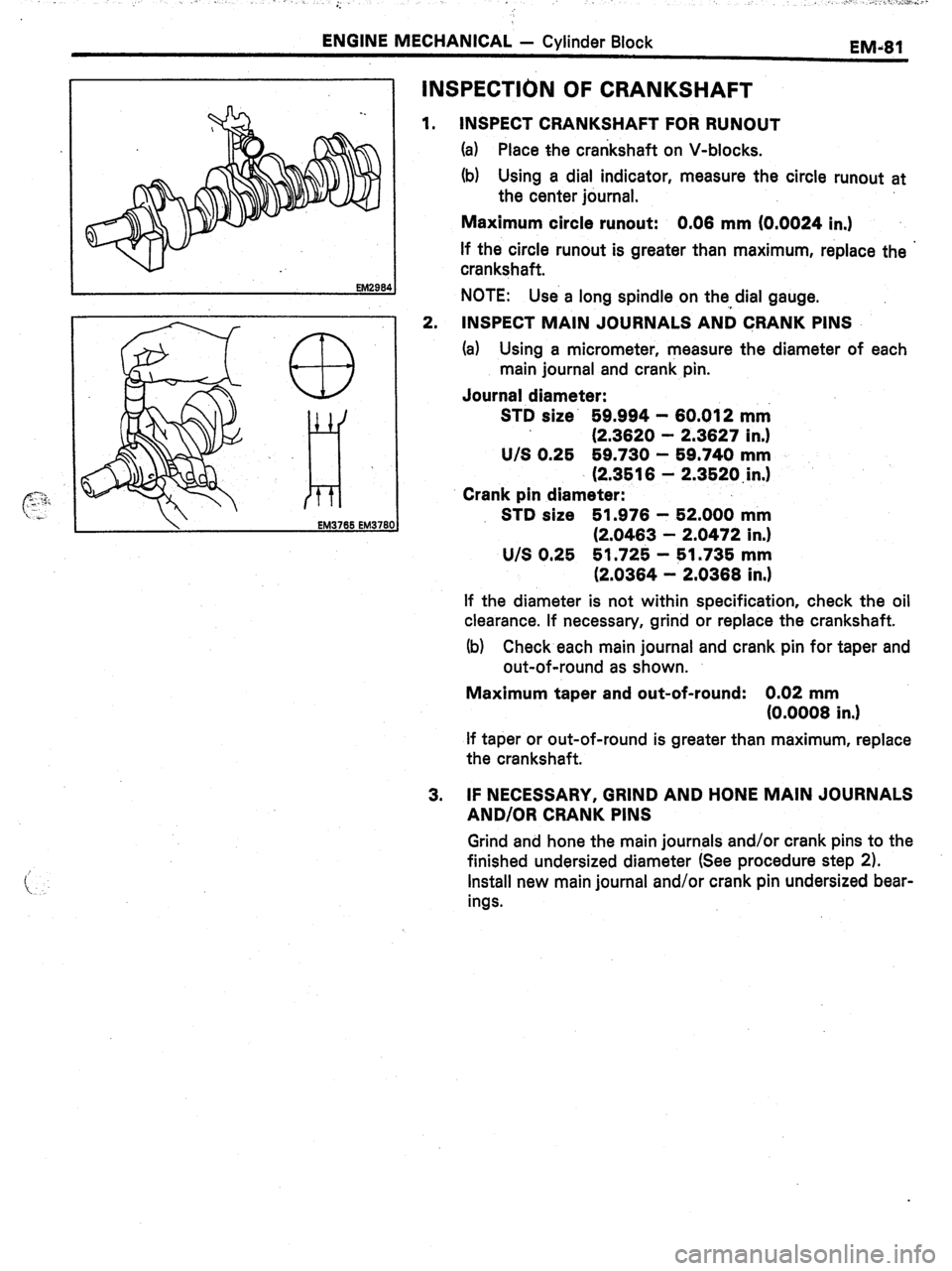
1. INSPECT CRANKSHAFT FOR RUNOUT
(a) Place the crankshaft on V-blocks.
(b) Using a dial indicator, measure the circle runout at
the center journal.
Maximum circle runout: 0.08 mm (0.0024 in.)
If the circle runout is greater than maximum, replace the ’
crankshaft.
NOTE: Use a long spindle on the,,dial gauge.
2. INSPECT MAIN JOURNALS AND CRANK PINS
(a) Using a micrometer, measure the diameter of each
main journal and crank pin.
Journal diameter:
STD size’ 59.994 - 60.012 mm
(2.3620 - 2.3627 in.1
U/S 0.25 59.730 - 59.740 mm
(2.3516 - 2.3520,in.I
Crank pin diameter:
STD size 51.976 - 52.000 mm
(2.0463 - 2.0472 in.)
U/S 0.25 51.725 - 51.735 mm
(2.0364 - 2.0368 in.)
If the diameter is not within specification, check the oil
clearance. If necessary, grind or replace the crankshaft.
(b) Check each main journal and crank pin for taper and
out-of-round as shown.
Maximum taper and out-of-round: 0.02 mm
(0.0008 in.1
If taper or out-of-round is greater than maximum, replace
the crankshaft.
3. IF NECESSARY, GRIND AND HONE MAIN JOURNALS
AND/OR CRANK PINS
Grind and hone the main journals and/or crank pins to the
finished undersized diameter (See procedure step 2).
Install new main journal and/or crank pin undersized bear-
ings.