Page 266 of 346
IQ-12 IGNITION~.SYSTEM - On-Vehicle Inspection (‘IM-GTE)
. ON-VEHICLE’INSPECTION
(7M-GTE)
SPARK TEST
EM35
3. NOTE: Perform this test to check that voltage is coming
from the ignition coil to spark plug.
DISCONNECT NO.1 AIR CLEANER HOSE
DISCONNECT FOLLOWING CABLES AND ROD:
(a) Accelerator link w/ cable
(b) Accelerator rod
(cl (A/T)
Throttle cable
REMOVE ISC PIPE
(a) Disconnect the six hoses from ISC pipe.
(b) Remove the two bolts and ISC pipe.
REMOVE PCV PIPE WITH HOSES
(a) Remove the oxygen sensor wire from two clamps.
(b) Disconnect the No.4 PCV hose from the PCV pipe.
(c) Remove the two bolts.
(d) Disconnect the PCV pipe with hoses from the
cylinder head covers and throttle body.
:
5. REMOVE INTAKE AIR CONNECTOR
(a) Disconnect the air valve hose from the intake air con-
nector.
(b) Loosen the clamp and remove the two bolts.
ic) Remove the intake air connector.
Page 267 of 346

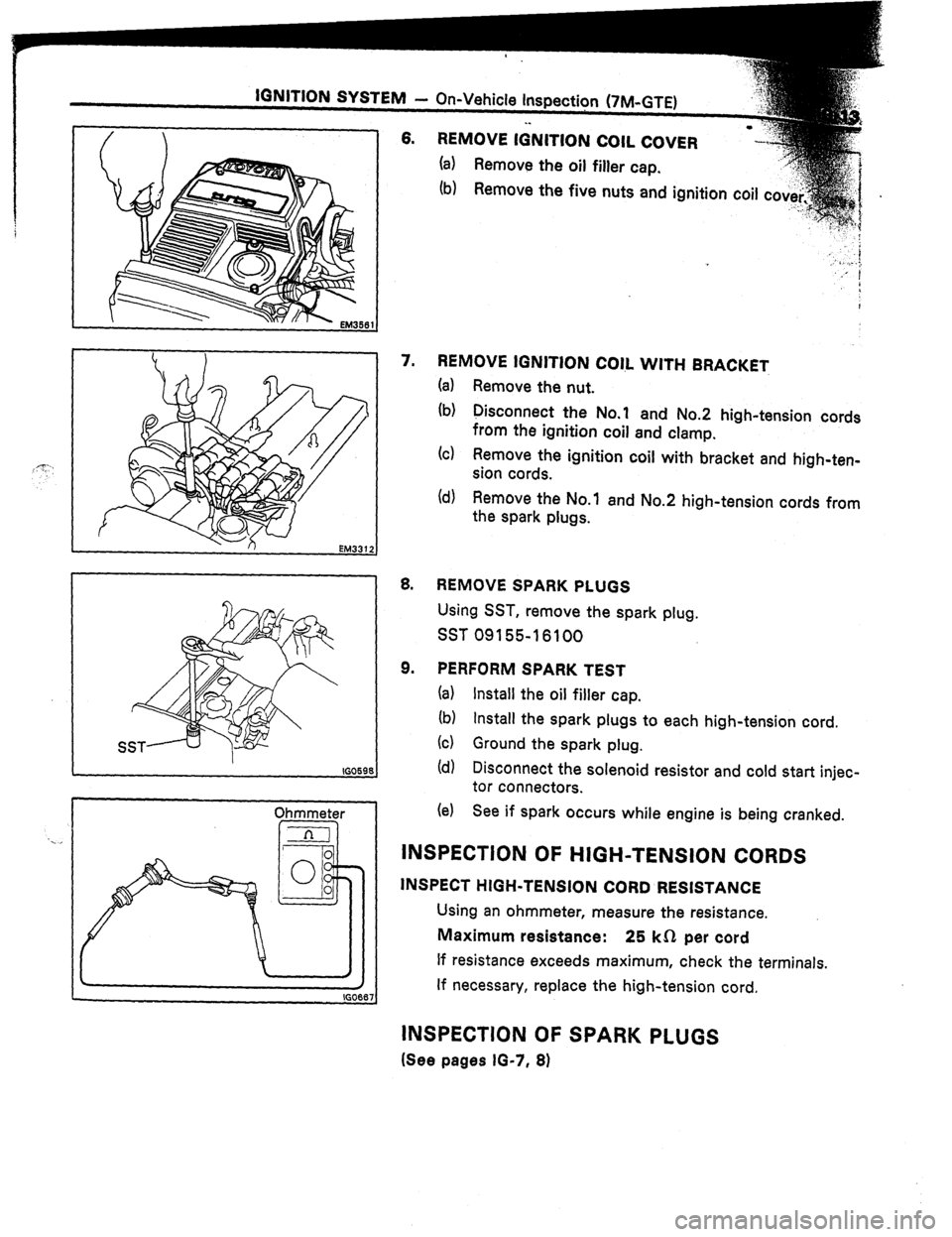
6. REMOVE IGNITION COIL COVER
(a) Remove the oil filler cap.
‘...”
I I
I(30598
Ohmmeter
/
IGO
7. REMOVE IGNITION C0l.L WITH BRACKET
(a) Remove the nut.
(b) Disconnect the No.1 and No.2 high-tension cords
from the ignition coil and clamp.
(cl Remove the ignition coil with bracket and high-ten-
sion cords.
id) Remove the No.1 and No.2 high-tension cords from
the spark plugs.
8.
9. REMOVE SPARK PLUGS
Using SST, remove the spark plug.
SST 09155-16100
PERFORM SPARK TEST
Ia) Install the oil filler cap.
(b) Install the spark plugs to each high-tension cord.
(4 Ground the spark plug.
(d) Disconnect the solenoid resistor and cold start injec-
tor connectors.
(e) See if spark occurs while engine is being cranked.
INSPECTION OF HIGH-TENSION CORDS
INSPECT HIGH-TENSION CORD RESISTANCE
Using an ohmmeter, measure the resistance.
Maximum resistance: 25 kfl per cord
If resistance exceeds maximum, check the terminals.
If necessary, replace the high-tension cord.
INSPECTION OF SPARK PLUGS
(See pages IG-7, 8)
Page 268 of 346
IG-14 IGNITION.SYSTEM - On-Vehicle Inspection (7M-GTE)
INSPECTIoN OF IGNlTlOhi COIL-
1. INSPECT POWER SOURCE LINE
(a) Disconnect the high-tension cord from the ignition
coil.
(b) Disconnect the ignition coil connectors.
(c) Turn the ignition switch ON,
Voltmeter
ccl
0
!I
0 0
dz 160668
I IGOt
I - IG067
I \ ’ IG087'
(d) Using a voltmeter, measure the voltage between ter-
minal 1 and body ground.
Voltage: Approx. 12 V
2. INSPECT PRIMARY COIL RESISTANCE
Using an ohmmeter, measure the resistance between the
positive (+I and negative (-1 terminals.
Primary coil resistance (cold): 0.3 - 0.5 R
NOTE: Because is inside the coil, it is impossible to
measure secondary coil resistance.
3. INSPECT IGNITION COIL GROUND
Using an ohmmeter, check that there is no continuity be-
tween the ignition coil terminal and body ground.
4. IF NECESSARY, REPLACE IGNITION COIL
Using a hexagon key wrench 3 mm (0.12 in.), replace the
ignition coil.
Page 271 of 346

IGNITION SYSTEM
- On-Vehicle Inspection (7M-GTE)
lG4::7:
Voltmeter
4-x
: .
‘s...
Ohmmeter
IFal
Ohmmeter
Ohmmeter
IGOW A B C-
INSPECTION -bF IGNITER i
1.
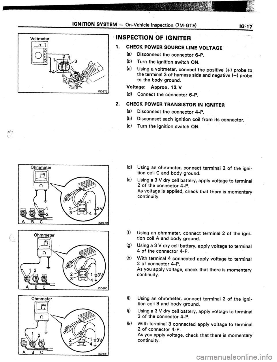
CHECK POWER SOURCE LINE VOLTAGE
(a) Disconnect the connector 6-P.
(b) Turn the ignition switch ON.
(c) Using a voltmeter, connect the positive (+I probe to
the terminal 3 of harness side and negative (-1 probe
to the body ground.
Voltage: Approx. 12 V
(d) Connect the connector 6-P.
2. CHECK POWER TRANSISTOR IN IGNITER
(a)
(b)
(c)
(d)
(e)
(f)
(d
(h)
(i)
(j)
(k) Disconnect the connector 4-P.
Disconnect each ignition coil from its connector.
Turn the ignition switch ON.
Using an ohmmeter, connect terminal 2 of the igni-
tion coil C and body ground.
Using a 3 V dry cell battery, apply voltage to terminal
2 of the connector 4-P.
As voltage is applied, check that there is momentary
continuity.
Using an ohmmeter, connect terminal 2 of the igni-
tion coil A and body ground.
Using a 3 V dry cell battery, apply voltage to terminal
4 of the connector 4-P.
With terminal 4 connected apply voltage to terminal
2 of connector 4-P.
As you apply voltage, check that there is momentary
continuity.
Using an ohmmeter, connect terminal 2 of the igni-
tion coil B and body ground.
Using a 3 V dry cell battery, apply voltage to terminal
3 of the connector 4-P.
With terminal 3 connected apply voltage to terminal
2 of connector 4-P.
As you apply voltage, check that there is momentary
continuity.
Page 272 of 346
IGNITION SYSTEM - On-Vehicle Inspection (7M-GTE)
NE Pickup Gl Pickup G2 Pickup
.’ INSPECTION dF -CAM .POSITION SENSOR
1. INSPECT AIR GAP
Using a thickness gauge, measure the gap between the ?
signal rotor and pickup coil projection.
Air gap: 0.2 - 0.4 mm (0.008 - 0.016 in.)
If the gap is not within specification, replace the cam posi-
tion sensor.
2. INSPECT PICKUP COILS
Using an ohmmeter, check resistance of the pickup coil.
Gl pickup coil resistance:
Gl -GQ 140-180n
62 pickup coil resistance:
G2-GO 140-180n
NE pickup coil resistance:
NE-GO 140-180n
If the resistance is not as specified, replace the cam posi-
tion sensor.
Page 282 of 346
-.
. .
..,I -_
LUBRICATION SYSTEM: . . I-
Page
DESCRIPTION . . ..*.*.........*......*........
LU-2
TROUBLESHOOTING ..I....*........*.‘....... b-4
OIL PRESSURE CHECK . . , . . . . . .
l . . . . . . , . . . . . . . ‘LU-5
REPLACEMENT OF ENGINE OIL
AND OIL FILTER I*......**.~.....~..,,,,..,.
LU-6
OIL PUMP *I...~.......~.~.,,,...~...~‘,,...,.
LU-6
OIL COOLER AND OIL PRESSURE
REGULATOR (7M-GE) . . . . . . . . . . . . . . . . . . . . . . . LU-15
OIL COOLER AND OIL PRESSURE
REGULATOR (7M-GTE) . . . . . . . . . . . . . . a. . . . . . LU-16
Page 284 of 346

LUBRICATION SYSTEM - Description
.,LU-3
A pressure feeding lubrication system has been
adopted to supply oil to the moving parts of this
engine. The lubrication system consists of an oil
pan, oil pump, oil filter and other external parts
which supply oil to the moving parts in the engine
block. The oil circuit is shown in the illustration at
the top of the previous page. Oil from the oil pan is
pumped up by the oil pump. After it passes
through the oil filter, it is fed through the various
oil holes in the crankshaft and cylinder block. After
passing through the cylinder block and performing
its lubricating function, the oil is returned by gra-
vity to the oil pan. A dipstick on the side of the
cylinder block is provided to check the oil level.
OIL PUMP
The oil pump pumps up oil from the oil pan and
sends it under pressure to the various parts of the
engine. An oil strainer is mounted in front of the
inlet to the oil pump. The oil pump itself is a gear
pump, which uses a drive gear and driven gear
inside the pump body. When the drive gear
rotates, the driven gear rotates in the opposite
direction. When the gear teeth disengage oil is
drak n in, and when the gear teeth engage oil is
discharged.
OIL PRESSURE REGULATOR
At high engine speeds, the engine oil supplied
bY thr oil pump exceeds the capacity of the engine
10 utiiize it.
For that reason, the oil pressure regula-
tor i ,>rks to prevent an oversupply of oil. During
norm.tl oil
supply, a coil spring and valve keep the
bYPcls:s closed, but when too much oil is being fed,
the I’tt’essure becomes extremely high, overpower-
9 the force of the spring and opening the valves.
This ;:ilows the excess oil to flow through the
Yalvtj :snd return to the oil pan. Olii FILTER
The oil filter is a full flow type filter with a built-
in paper filter element. Particles of :metal ‘from
wear, a&born dirt, carbon and other impurities can ’
get in the oil during use and could cause acceler-
ated wear or siezing if allowed to circulate through
the engine. The oil filter, integrated into the oil line,
removes these impurities as the oil passes through
it. The filter is mounted outside the engine to
simplify replacement of the filter element. A relief
valve is also included ahead of the filter element to
relieve the high oil pressure in case the filter ele-
ment becomes clogged with impurities. The relief
valve opens when the oil pressure overpowers the
force of the spring. Oil passing through the relief
valve bypasses the oil filter and flows directly into
the main oil hole in the engine.
Page 286 of 346

rutmwCiA rlON SYSTEM - Oil Pressure Che,ck’:q. .’ ‘f,“,; .! . ,_ _,, __ _ ,-tiu,e
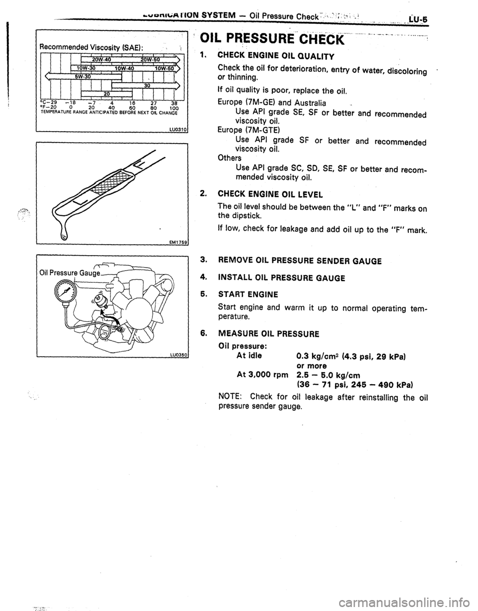
Recommended
Viscositv (SAE):
I 1 1 1 h T-29 -,a 7 “F-20 0 TEMPEAATURE LY
I I b I I I I
I
z 4 16 36
/
RANGE ANTICIPA$O B&i% NEXT OIL CHANGE 100 ._. .-- . . .
?’ OIL PR,ESSURE’($liCK . .._.
-. - -_-. _
. _ _.. _ _...
1. 1 CHECK-ENGINE OIL QUALITY
Check the oil for deterioration, entry of water, discoloring .
or thinning.
2.
3.
4.
5.
6. If oil quality is poor, replace the oil,
Europe (‘IM-GE) and Australia *
Use API grade SE, SF or better and recommended
viscosity oil.
Europe (7M-GTE)
Use API grade SF or better and recommended
viscosity oil.
Others
Use API grade SC, SD, SE, SF or better and recom-
mended viscosity oil.
CHECK ENGINE OIL LEVEL
The oil level should be between the “L” and “F” marks on
the dipstick.
If low, check for leakage and add oil up to the “F” mark.
REMOVE OIL PRESSURE SENDER GAUGE
INSTALL OIL PRESSURE GAUGE
START ENGINE
Start engine and warm it up to normal operating tem-
perature.
MEASURE OIL PRESSURE
Oil pressure:
At idle 0.3 kg/cm2 (4.3 psi, 29 kPa1
or more
At 3,000 rpm 2.5 - 5.0 kg/cm
(36 - 71 psi, 245 - 490 kPa1
NOTE: Check for oil leakage after reinstalling the oil
pressure sender gauge.