Page 247 of 346
ENGINE :MECHANICAL.;:y Cylinder, B&k:
Elg781i.
.,. ,.,. .._. >,, \I . ,_
“. 1 . , ,_ ., “_ , ; . . .
EM2994
SST (b) Apply MP grease to a new oil, seal lip.
(~1, Using--SST and a hammer, tap in-the oil seal.
SST 09214-60010 and 09506-3501.0 ;”
.
2. REPLACE CRANKSHAFT REAR OIL SEAL ‘-. ‘. :
A. If the rear oil seal retainer is removed from the,
cylinder block: ‘: <
.:
(a) Using a screwdriver and hammer, tap out the oil seal.
(b) Using SST and a hammer, tap in a new oil seal.
SST 09223-41020
(cl Apply MP grease to the oil seal lip.
8. If the rear oil seal retainer is installed to the
cylinder block:
(a) :Using a knife, cut off the lip of the oil seal as shown.
(b) Using a screwdriver, pry out the oil seal.
CAUTION: Be careful not to damage the crankshaft.
Tape the screwdriver tip.
(c) Check the oil seal lip contact surface of the
crankshaft for cracks or damage.
(d)
Apply MP grease to a new oil seal lip.
(e)
Using SST and a hammer, tap in the oil seal.
SST 09223-41020
Page 248 of 346
EM-86
,, ENGINE MF@ANl,CAL - Cjrlinder Block
EM456:
?==--zpe EM0262 EM1 761
3. REPLACE PUM+ DRIVE SHAFT OIL SEAL
A. If the timing b&t case is removed from the
cyjinder block:
(a) Using a screwdriver and hammer, tap out the oil seal.
(b) Using SST and a hammer, tap in a new oil seal.
SST 09214-41ClO C
, . . .
(c) Apply MP grease to the oil seal, lip.
A--
*- .
& If the timing belt case is installed to the cylinder
block:
(a) Using a knife, cut off the lip of the oil seal as shown.
(b) Using a screwdriver, pry .out the oil seal.
CAUTION: Be careful not
to damage the crankshaft.
Tape the screwdriver tip.
(c) Check the oil seal lip contact surface of the pump
drive shaft for cracks or damage.
(d) Apply MP grease to a new oil seal lip.
(e) Using SST and a hammer, tap in the oil seal.
SST 09214-41010
Page 251 of 346
ENGINE MECHANICAL A Cylinder Block
EM-@-
3.
4.
5. (a)
Align the bearing claw with the the claw -groove of.
the main bearing cap or cylind,er block.
(b)
Install the bearing in the cylinder block and bearing
caps.
GAUTION:
Install the bearing with the oil hole in the
block.
INSTALL UPPER THRUST WASHERS
Install the thrust washers under the No. 4 main journal
position of the block with the oil grooves facing outward.
PLACE &ANKSHAFT ON CYLINDER BLOCK
INSTALL MAIN BEARING CAPS AND LOWER THRUST
WASHERS
NOTE: Each bearing cap has a number and front mark.
(a) Install the thrust washers on the No. -4 bearing cap
with the grooves facing outward.
(b) Install the bearing caps in numbered order with
arrows facing forward.
(c) Install and uniformly tighten the fourteen cap bolts in
several passes, in the sequence shown.
Torque: 1,040 kg-cm (75 ft-lb, 102 N.mI
(d) Check that the crankshaft turns smoothly.
(e) Check the crankshaft thrust clearance.
(See step 21 on page EM-701
Page 252 of 346

EM-90 ENdIM IV~ECHAN~CAL - Cylinder Block
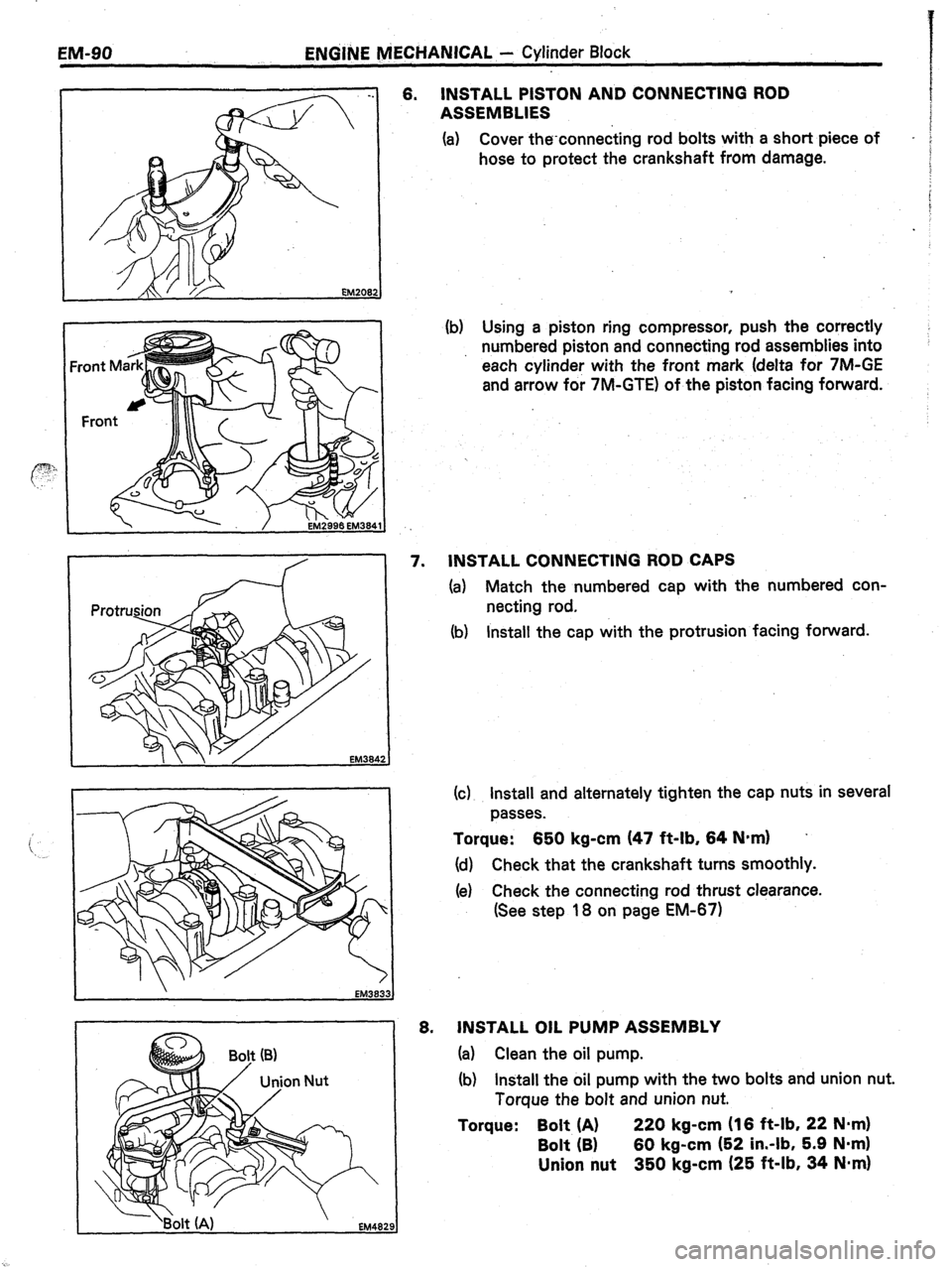
6. INSTALL PISTON AND CONNECTING ROD
ASSEMBLIES
(a) Cover the-connecting rod bolts with a short piece of
-
hose to protect the crankshaft from damage.
(b) Using a piston ring compressor, push the correctly
numbered piston and connecting rod assemblies into
each cylinder with the front mark (delta for 7M-GE
and arrow for 7M-GTE) of the piston facing forward.
EM384
EM383.
EM482
7. INSTALL CONNECTING ROD CAPS
(a) Match the numbered cap with the numbered con-
necting rod.
(b) Install the cap with the protrusion facing forward.
(c) Install and alternately tighten the cap nuts in several
passes.
Torque: 650 kg-cm (47 ft-lb, 64 N-m) .
(d) Check that the crankshaft turns smoothly.
(e) Check the connecting rod thrust clearance.
(See step 18 on page EM-671
6. JNSTALL OIL PUMP ASSEMBLY
(a) Clean the oil pump.
(b) Install the oil pump with the two bolts and union nut.
Torque the bolt and union nut.
Torque: Bolt (A) 220 kg-cm (16 ft-lb, 22 N*m)
Bolt (B) 60 kg-cm (52 in.-lb, 5.9 Nom)
Union nut 350 kg-cm (25 ft-lb, 34 Nmrn)
Page 256 of 346
16-2 IGNITION SYSTEM - precautions
-.
PRECAUTIONS
1.
2.
3.
4.
5.
6.
. *
Do not leave the ignition switch on for more than 10
minutes if the engine does not start.
When a tachometer is connected to the system; con-
nect the tachometer test probe to the check connector
terminal IG 0 .
CHECK CONNECTOR LOCATION:
See pages FI-110, 111
As some tachometers are not compatible with this
ignition system, we recommended that you confirm
the compatibility of your unit before using.
NEVER allow the tachometer terminals to touch
ground as it could result in damage to the igniter and/
or ignition coil.
Do not disconnect the battery while the engine is run-
ning.
Make sure that the igniter is properly grounded to the
body.
Page 259 of 346

IGNITION SYSTEM - On-Vehicle Inspection (7M-GE)
IO-6 *
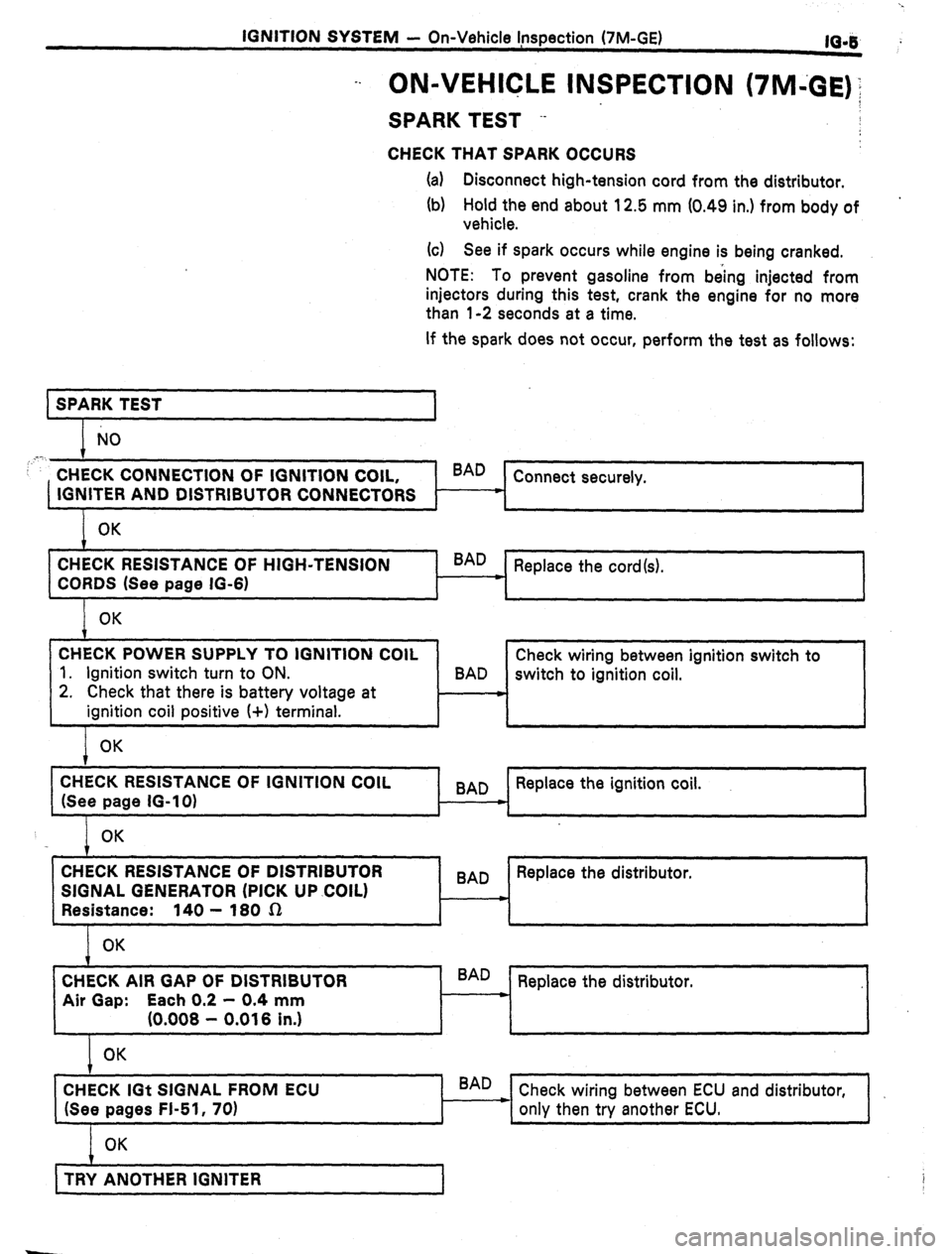
-. ON-VEHICLE INSPECTION (7M43E)‘;
SPARK TEST --
CHECK THAT SPARK OCCURS
(a) Disconnect high-tension cord from the distributor.
(b) Hold the end about 12.5 mm (0.49 in.) from body of
vehicle.
(G) See if spark occurs while engine is being cranked.
NOTE: To prevent gasoline from being injected from
injectors during this test, crank the engine for no more
than l-2 seconds at a time.
If the spark does not occur, perform the test as follows:
SPARK TEST
1
NO
,‘.
CHECK CONNECTION OF IGNITION COIL, BAD
Connect securely.
IGNITER AND DISTRIBUTOR CONNECTORS c
OK
CHECK RESISTANCE OF HIGH-TENSION
CORDS (See page IG-6) ’ BAD
Replace the cord(s).
OK
CHECK POWER SUPPLY TO IGNITION COIL
1. Ignition switch turn to ON.
2. Check that there is battery voltage at
ignition coil positive I+) terminal. Check wiring between ignition switch to
BAD
switch to ignition coil.
OK
CHECK RESISTANCE OF IGNITION COIL
(See page IG-10) 9
BAD Replace the ignition coil.
*
OK
1 , , 1
CHECK RESISTANCE OF DISTRIBUTOR
SIGNAL GENERATOR (PICK UP .COIL)
Resistance: 140 - 180 sz
OK BAD Replace the distributor.
m
CHECK AIR GAP OF DISTRIBUTOR
Air Gap: Each 0.2 - 0.4 mm
(0.008 - 0.016 in.) BAD
Replace the distributor.
L
OK
CHECK IGt SIGNAL FROM ECU
(See pages FI-51, 70) BAD
Check wiring between ECU and distributor,
only then try another ECU.
OK
t ,
TRY ANOTHER IGNITER
1 i
Page 263 of 346

IGNITION SYSTEM
- On-Vehicle Inspection (7M-GE)
,“lG-9
16031
0.8 mm (7M-GTE)
1 .I
mm (7M-GE)
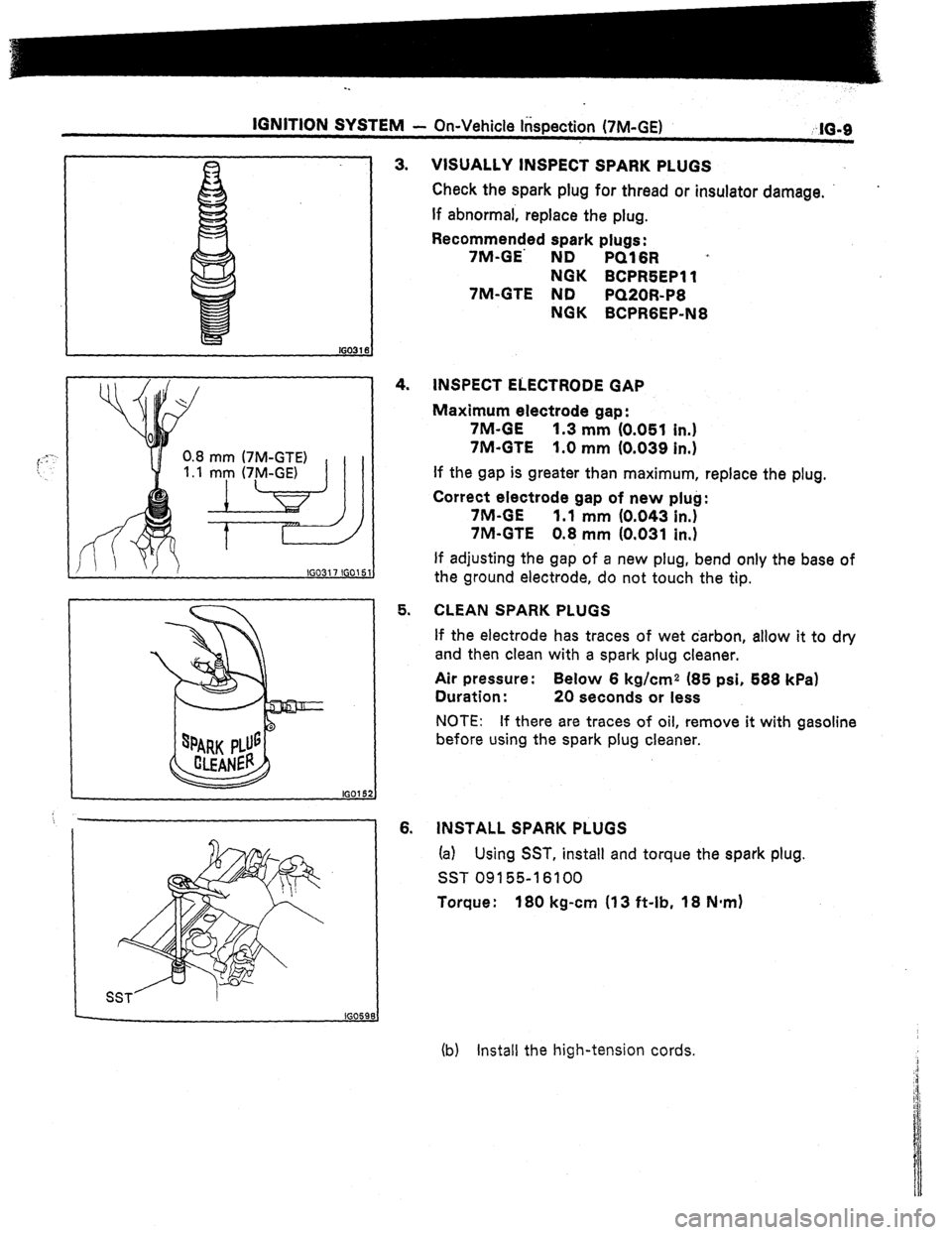
VISUALLY INSPECT SPARK PLUGS
Check the spark plug for thread or insulator damage.
If abnormal, replace the plug.
Recommended spark plugs:
7M-GE’ ND
PQ16R ’
NGK BCPR5EPll
7M-GTE ND
PQ20R-P6
NGK BCPRGEP-N8
INSPECT ELECTRODE GAP
Maximum electrode gap:
7M-GE
1.3 mm (0.051 in.)
7M-GTE 1.0 mm (0.039 in.)
If the gap is greater than maximum, replace the plug.
Correct electrode gap of new plug:
7M-GE
1.1 mm (0.043 in.)
7M-GTE 0.8 mm (0.031 in.)
If adjusting the gap of a new plug, bend only the base of
5. CLEAN SPARK PLUGS
6. the ground electrode, do not touch the tip.
If the electrode has traces of wet carbon, allow it to dry
and then clean with a spark plug cleaner.
Air pressure: Below 6 kg/cm2 (85 psi, 588 kPa)
Duration : 20 seconds or less
NOTE: If there are traces of oil, remove it with gasoline
before using the spark plug cleaner.
INSTALL SPARK PLUGS
(a) Using SST, install and torque the spark plug.
SST 09155-l 6100
Torque : 180 kg-cm (13 ft-lb, 18 N*m)
(b) Install the high-tension cords.
Page 265 of 346
lGNlTlON S+S
1
EM - On-Vehicle Inspection (‘IM-GE)
INSPECTION 6F DISTRIBUTOR
IG-11
1. lNSPECT AIR GAPS
Using a thickness gauge, measure the gap between the .
signal rotor and pickup coil projection.
Air gap: 0.2 - 0.4 mm (0.008 - 0.016 in.)
If the gap is not as specified, replace’the distributor. NE Pickup
Gl Pickup G2 Pickup
INSPECT PICKUP COILS
Using an ohmmeter, check resistance of the pickup coil.
Gl pickup coil resistance:
61-00 1’40-180fi
G2 pickup coil resistance:
62-G@ 140-18Os1
NE pickup coil resistance:
NE-GO 140-180 0
If the resistance is not as specified, replace the distributor.