Page 287 of 346

-.
LUBRICATION SYSTEM
- Replacement.of Engine Oil and Oil Filter
L&.7*.
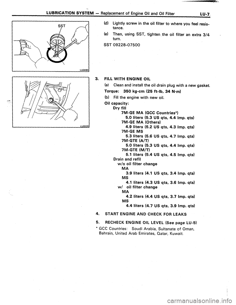
(d) Lightly screw in the oil filter to where you feel resis-
tance.
(el Then, using SST, tighten.the oil filter an extra 3/4
turn. .
SST 09228-07500
3. FILL WITH ENGINE OIL
(a) Clean and install the oil drain plug with a new gasket.
Torque: 350 kg-cm (25 ft-lb, 34 N.m)
(b) Fill the engine with new oil.
Oil capacity:
Dry fill
7M-GE MA (GCC Countries*)
5.0 liters (5.3 US qts, 4.4 Imp. qts)
‘/M-GE MA (Others)
4.9 liters (5.2 US qts, 4.3 Imp. qts)
7M-GE MS
5.3 liters (5.6 US qts, 4.7 Imp. qts)
7M-GTE (A/T)
5.0 liters (5.3 US qts, 4.4 Imp. qts)
7M-GTE (M/T)
5.1 liters (5.4 US qts, 4.5 Imp. qts)
Drain and refil
w/o oil filter change
MA
3.9 liters (4.1 US qts, 3.4 Imp. qts)
MS
4.1 liters (4.3 US qts, 3.6 Imp. qts)
w/ oil filter change
MA
4.2 liters (4.4 US qts, 3.7 Imp. qts)
MS
4.4 liters (4.7 US qts, 3.9 Imp. qts)
4.
START ENGINE AND CHECK FOR LEAKS
5. RECHECK ENGINE OIL LEVEL (See page LU-5)
’ GCC Countries: Soudi Arabia, Sultanate of Oman,
Bahrain, United Arab Emirates, Qatar, Kuwait.
Page 288 of 346
-.
LU-6
LUBRICATION SYSTEM - Replacement-of Engine Oil and Oil Filter
REPLACEMENT OF ENGINE OIL
AND OIL FILTER
1.
DRAIN ENGINE OIL
(a) Remove the oil filler cap.
(b) Remove the oil drain plug and drain the oil into a con-
tainer.
2.
REPLACE OIL FILTER
(a) Using SST, remove the oil filter (located on right side
of the engine block).
SST 09228-07500
NOTE (7M-GTE):
Remove the oil filter taking it over the
engine mounting bracket and down between the bracket
and No. 1 suspension crossmember.
(b)
Clean and check the oil filter installation surface.
(c) Apply clean engine oil to the gasket of the new oil
filter. o
Page 289 of 346

-.
LUBRICATION SYSTEM
- Replacement.of Engine Oil and Oil Filter
L&7_
4.
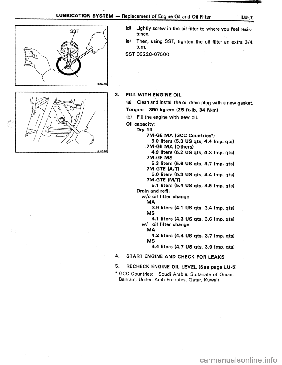
5. (d) Lightly screw in the oil filter to where you feel resis-
tance.
(e) Then, using SST, tighten. the oil filter an extra 3/4 .
turn.
SST 09228-07500
FILL WITH ENGINE OIL
(a) Clean and install the oil drain plug with a new gasket.
Torque: 350 kg-cm (25 ft-lb, 34 N-m)
(b) Fill the engine with new oil,
Oil capacity:
Dry fill
7M-GE MA (GCC Countries*)
5.0 liters (5.3 US qts, 4.4 Imp. qts)
7M-GE MA (Others)
4.9 liters (5.2 US qts, 4.3 Imp. qts)
7M-GE MS
5.3 liters (5.6 US qts, 4.7 Imp. qts)
7M-GTE (A/T)
5.0 liters (5.3 US qts, 4.4 Imp. qts)
7M-GTE (M/T)
5.1 liters (5.4 US qts, 4.5 Imp. qts)
Drain and refil
w/o oil filter change
MA
3.9 liters (4.1 US qts, 3.4 Imp. qts)
MS
4.1 liters (4.3 US qts, 3.6 Imp. qts)
w/ oil filter change
MA
4.2 liters (4.4 US qts, 3.7 Imp. qts)
MS
4.4 liters (4.7 US qts, 3.9 Imp. qtsl
START ENGINE AND CHECK FOR LEAKS
RECHECK ENGINE OIL LEVEL (See page LU-5)
l GCC Countries: Soudi Arabia, Sultanate of Oman,
Bahrain, United Arab Emirates, Qatar, Kuwait.
Page 293 of 346

LG&RICATION SYSTEM - Oil Pump
L.!J:ll
.... ..- .._.~.“.“._ _ ,.. _,-
INSPECTION OF OIL PUMP
1.
2.
3.
4.
~. -.--. . ._. I ”
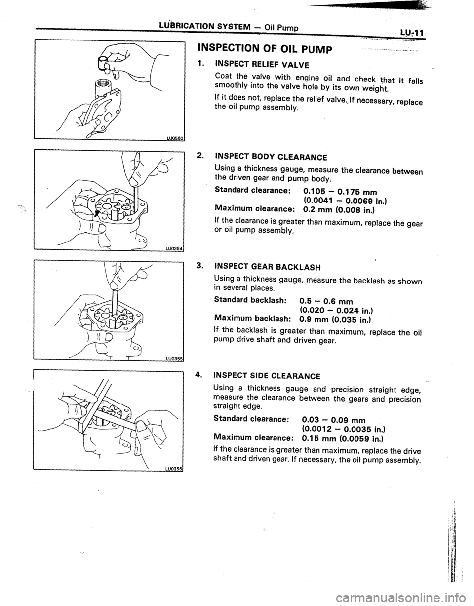
INSPECT RELIEF VALVE
Coat the valve with engine oil and check that it falls
smoothly into the valve hole by its own weight,
If it does not, replace the relief valve.,If necessary, replace
the oil pump assembly.
INSPECT BODY CLEARANCE
Using a thickness gauge, measure the clearance between
the driven gear and pump body.
Standard clearance:
0.105 - 0.175 mm
(0.0041 - 0.0069 in.1
Maximum clearance: 0.2 mm (0.008 in.)
If the clearance is greater than maximum, replace the gear
or oil pump assembly.
INSPECT GEAR BACKLASH
Using a thickness gauge, measure the backlash as shown
in several places.
Standard backlash: 0.5 - 0.6 mm
(0.020 - 0.024 in.)
Maximum backlash: 0.9 mm (0.035 in.)
If the backlash is greater than maximum, replace the oil
pump drive shaft and driven gear.
INSPECT SIDE CLEARANCE
Using a thickness gauge and precision straight edge,
measure the clearance between the gears and precision
straight edge.
Standard clearance:
0.03 - 0.09 mm
(0.0012 - 0.0035 in.)
Maximum clearance: 0.15 mm (0.0059 in.)
If the clearance is greater than maximum, replace the drive
shaft and driven gear. If necessary, the oil pump assembly.
Page 294 of 346
LU-12
-.
LUBRICATION SYSTEM - Oij Pump
LUOJS
ASSEMBLY AND OPERATION CHECK OF OIL
”
PUMP
(See page LU-8)
5. INSTALL OIL PUMP DRIVE SHAFT
Install the oil pump drive shaft, key, shaft drive gear,
spacer, and using snap ring pliers, install the snap ring.
INSTALL OIL PUMP DRIVEN GEAR
INSTALL OIL PUMP COVER
Install the oil pump cover with the five bolts.
Torque the bolts.
Torque: 75 kg-cm (65 in.-lb, 7.4 N-m)
INSTALL RELIEF VALVE
Install the relief valve and spring with the relief valve plug.
Torque the plug.
Torque:
375 kg-cm (27 ft-lb, 37 N.m)
CHECK PUMP OPERATION
(a) Immerse the suction end of the pump into clean
engine oil and turn the shaft counterclockwise. Oil
should come out of the discharge hole.
(b) Close the discharge hole with your thumb, and turn
the shaft as before. The shaft should be difficult to
turn.
Page 296 of 346
bf3lCA~l0N SYSTEM - Oil Pump
2. INSTALL OIL PAN
(a) Remove any old packing (FIPG) material and be care-
ful not to drop any oil on the contact surfaces of the
oil pan and cylinder block.
l Using a razor blade and gasket scraper, remove all
the packing (FIPG) material from the gasket sur-
faces.
0 Thoroughly clean all components to remove all the
loose material.
l Clean both sealing surfaces with a non-residue
solvent.
CAUTION: Do not use a solvent which will affect the
painted surfaces.
ib) Apply seal packing to the oil pan as shown in the
figure.
Seal packing: Part No. 08826-00080 or equivalent
0 Install a nozzle that has been cut to a 5 mm (0.20
in.) opening.
(c) Install the oil pan with the bolts and nuts.
Torque : 130 kg-cm (9 ft-lb, ‘I3 N-m)
3. FILL WITH ENGINE OIL (See step 3 on page LU-7)
4. START ENGINE AND.CHECK FOR LEAKS
‘. 5. RECHECK OIL LEVEL (See step 2 on page LU-5)
Page 299 of 346

LUBRICATION SYSTENl
- Qii Cooler and oil Pressure. Regulator (-/M-GE)
LU-17.
._ .
w
e
0
LUO48f
REMOVAL AND DISASSEMBLY OF OIL
PRESSURE REGULATOR
(See pages LU-15, 16)
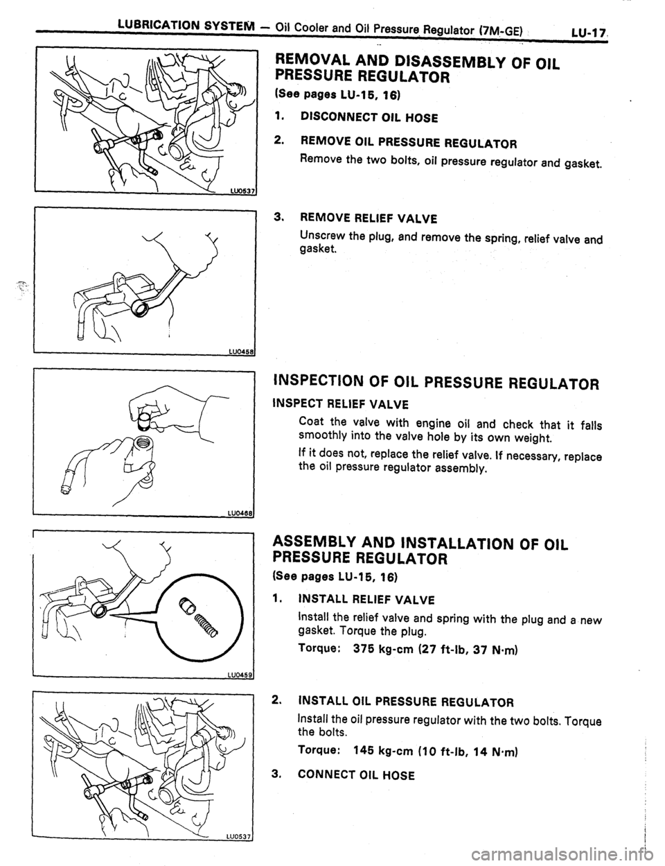
1. DISCONNECT OIL HOSE
2. REMOVE OIL PRESSURE REGULATOR
Remove the two bolts, oil pressure regulator and gasket.
3. REMOVE RELIEF VALVE
Unscrew the plug, and remove the spring, relief valve and
gasket.
INSPECTION OF OIL PRESSURE REGULATOR
INSPECT RELIEF VALVE
Coat the valve with engine oil and check that it falls
smoothly into the valve hole by its own weight.
If it does not, replace the relief valve. If necessary, replace
the oil pressure regulator assembly.
ASSEMBLY AND INSTALLATION OF OIL
PRESSURE REGULATOR
(See pages LU-15, 16)
1. INSTALL RELIEF VALVE
Install the relief valve and spring with the plug and a new
gasket. Torque the plug.
Torque:
375 kg-cm (27 ft-lb, 37 N-m)
2. INSTALL OIL PRESSURE REGULATOR
Install the oil pressure regulator with the two bolts. Torque
the bolts.
Torque:
145 kg-cm (10 ft-lb, 14 N.m)
3, CONNECT OIL HOSE
Page 301 of 346
LUBRICATION SYSTENI - Oil Cooler and Oil Pressurr+ Regulator (7M-GTE)
’ 1” - 06Lu-19
---. “, -“-~~yII.
. .
INSPECTION OF RELIEF VALVE
Coat the valve with engine oil and check that it falls
smoothly into the valve hole by its own weight.
If it does not, replace the relief valve. If necessary,
replace
the oil filter bracket assembly.
INSTALLATION OF OIL ASSEMBLY AND
FILTER BRACKET
(See page LU-18)
1. INSTALL RELIEF VALVE
(a) Install the relief valve and spring.
(b) Install and torque the plug with a new gasket.
Torque: 375 kg-cm (27 ft-lb, 37 Nsm)
2.
INSTALL OIL FILTER
(See page LU-8)
3. INSTALL OIL FILTER BRACKET
(a) Install a new O-ring to bracket.
(b) Install a new gasket to union bolt.
(c) Put the oil filter bracket hole over the cylinder block
stud bolt and install the oil filter bracket with the
union bolt.
(d) Torque the union bolt.
Torque: 500 kg-cm (36’ ft-lb, 49 N*mI