1987 TOYOTA CELICA gas type
[x] Cancel search: gas typePage 44 of 346
FI-10 EFI SYSTEM - inspection Precautions
L Fco97 FlOO91
I
. FI159
i. 4 Gasket
New
‘Gasket
I / FM067 FHOE
Fulcrum Length
19
54
-.
(b) insert the tester probe into the connector from the
wiring side when-checking the continuity,,amperage
L
or voltage.
(c) Do not apply unnecessary force to the terminal.
(d) After checking, install the water-proofing rubber on
the connector securely.
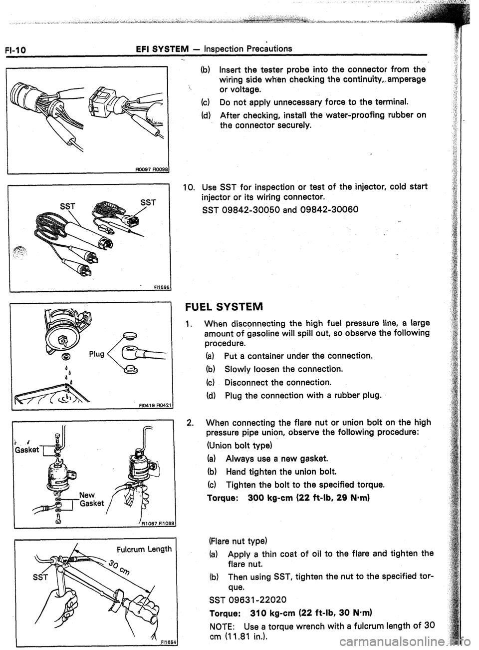
10. Use SST for inspection or test of the injector, cold start
injector or its wiring connector.
SST 09842-30050 and 09842-30060
FUEL SYSTEM
1.
2. When disconnecting the high fuel pressure line, a large
amount of gasoline will spill out, so observe the following
procedure.
(a) Put a container under the connection.
(b) Slowly loosen the connection.
(c) Disconnect the connection.
(d) Plug the connection with a rubber plug.
When connecting the flare nut or union bolt on the high
pressure pipe union, observe the following procedure:
(Union bolt type)
(a) Always use a new gasket.
(b) Hand tighten the union bolt.
(c) Tighten the bolt to the specified torque.
Torque: 300 kg-cm (22 it-lb, 29 N*m)
(Flare nut type)
(a) Apply a thin coat of oil to the flare and tighten the
flare nut.
(b) Then using SST, tighten the nut to the specified tor-
que.
SST 09631-22020
Torque: 310 kg-cm (22 ft-lb, 30 N*m)
NOTE: Use a torque wrench with a fulcrum length of 30
cm (11.81 in.).
Page 113 of 346
EFI SYSTEM - Fuel System
FI-79
. .
/
A Fulcrum Length
2 - 7 mm (0.08 1 0.28 in.)
Pipe Hose
k ’
em -m-d-‘,
--
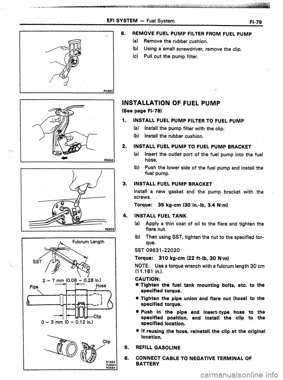
0 - 3 mm (0 - 0.12 in.) 6. REMOVE FUEL PUMP FILTER FROM FUEL PUMP
(a) Remove the rubber cushion.
(b) Using a‘small screwdriver, remove the clip.
(4 Pull out the pump filter.
INSTALLATION OF FUEL PUMP
(See page Fi-78)
1.
2. INSTALL FUEL PUMP FILTER TO FUEL PUMP
(a) Install’the pump filter with the clip.
(b) install the rubber cushion.
INSTALL FUEL PUMP TO FUEL PUMP BRACKET
(a) Insert the outlet port of the fuel pump into the fuel
hose.
(b) Push the lower side of the fuel pump and install the
fuel pump.
3. INSTALL FUEL PUMP BRACKET
Install a new gasket and the pump bracket with the
screws.
Torque: 35 kg-cm (30 in-lb, 3.4 N-m)
4.
INSTALL FUEL TANK
(a) Apply a thin coat of oil to the flare and tighten the
flare nut.
(b) Then using SST, tighten the nut to the specified tor-
que.
SST 09631~22020
Torque: 310 kg-cm (22 ft-lb, 30 N-m)
NOTE: Use a torque wrench with a fulcrum length 30 cm
(1 1 .181 in.).
CAUTION:
l Tighten the fuel tank mounting bolts, etc. to the
specified torque.
l Tighten ‘the pipe union and flare nut (hose) to the
specified torque.
l Push in the pipe and insert-type hose to the
specified position, and install the clip to the
specified location.
l If reusing the hose, reinstall the clip at the original
location,
5. REFILL GASOLINE
6. CONNECT CABLE TO NEGATIVE TERMINAL OF
BATTERY
Page 165 of 346
ENGINE MECHANICAL -, Description
EM-3
The 7M-GE, 7M-GTE engines are an in-line 6-
cylinder engine with the cylinders numbered l-2-
3-4-5-6 from the front. The crankshaft is sup-
ported by 7 bearings specified by the inside of the
crankcase. These bearings are made of kelmet.
.The crankshaft is integrated with 8 weights
which are cast along with it for balancing. Oil holes
‘are built into the crankshaft for supplying oil to the
connecting rods, pistons and other components.
These engine’s ignition order is l-5-3-6-2-4 .
The cylinder head is made of aluminum alloy, with
a cross flow type intake and exhaust layout and
with pent roof type combustion chambers. The
spark plugs are located in the center of the com-
bustion chambers.
Exhaust and intake valves are equipped with
irregular pitch springs with symmetrical ends
made of oil tempered silicon chrome steel wire
which are capable of following the valves even at
,high engine speeds.
Both the exhaust side cam shaft and the. intake
side cam shaft are driven by a single timing belt.
The cam journal is supported at 7 places between
the valve lifters of each cylinder and on the
cylinder head of front end. Lubrication of the cam
journal and cam is accomplished by oil being sup-
plied through the oiler port in the center of the
camshaft.
Adjustment of the valve clearance is done by
means of an outer shim type system, in which
valve adjusting shims are located above the valve
lifters. This permits replacement of the shims
without removal of the camshafts.
The resin timing belt cover is made in 2 pieces.
Pistons are made of highly temperature-resis-
tant aluminum alloy, and depressions are built into
the piston head to prevent interference with
valves.
Piston pins are the full-floating type, with the
pins fastened to neither the piston boss nor the
connecting rods. Instead, snap rings are fitted on
both ends of the pins, preventing the pins from
falling out.
The No. 1 compression ring is made of stainless
steel and the No. 2 compression ring is made of
cast iron. The oil ring is made of a combination of
stainless steel. The outer diameter of each piston
ring is slightly larger than the diameter of the
piston
and the flexibility of the rings allows them
to hug the cylinder walls when they are mounted
on the piston. Compression rings No. 1 and No. 2
work to prevent the leakage of gas from the
cylinder and the oil ring works to scrape oil off the
cylinder walls to prevent it from entering the com-
bustion chamber.
The cylinder block is made of cast iron. It has 6
cylinders which are approximately 1.6 times the
length of the piston stroke. The top of the cylin- ders is closed off by the cylinder head and the
lower end of the cylinders becomes the crankcase,
in which the crankshaft is installed. In addition,- the
cylinder block contains a water jacket, through
which coolant is pumped to cool the cylinders.
The .oil pan is bolted onto the botiom of the
cylinder block. The oil pan is an oil reservoir made .
of pressed steel sheet. A dividing plate’is included
-inside the oil pan to keep sufficient oil in the bot-
tom of the pan even when the vehicle is tilted. This
dividing plate also prevent5 the oil from making
waves when the vehicle is stopped suddenly and
thus shifting the oil away from the oil pump suc-
tion pipe.
Page 330 of 346
x-2 TURBOCHARGER SYSTEM - Description
.
DESCRIPTION
-.
“
Oxygen
. Turbine Wheel
Sensor
.
I Full-floating Bearing
Valve
Oil P&sage
From Oil Inlet Pipe
Intercooler Pipe Arrangement
TdO
CSOll5 Fl2
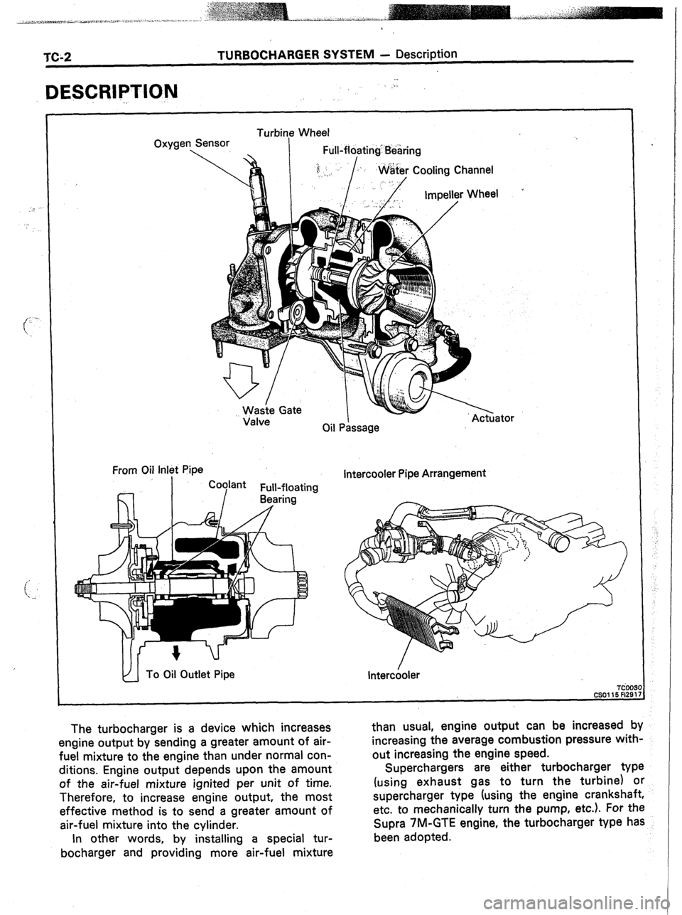
The turbocharger is a device which increases
engine output by sending a greater amount of air-
fuel mixture to the engine than under normal con-
ditions. Engine output depends upon the amount
of the air-fuel mixture ignited per unit of time.
Therefore, to increase engine output, the most
effective method is to send a greater amount of
air-fuel mixture into the cylinder. than usual, engine output can be increased by
.
increasing the average combustion pressure with-
out increasing the engine speed.
Superchargers are either turbocharger type
(using exhaust gas to turn the turbine) or
supercharger type (using the engine crankshaft,
etc. to mechanically turn the pump, etc.). For the
Supra 7M-GTE engine, the turbocharger type has
been adopted.
In other words, by installing a special tur-
bocharger and providing more air-fuel mixture
Page 331 of 346
Air
Cleaner
i
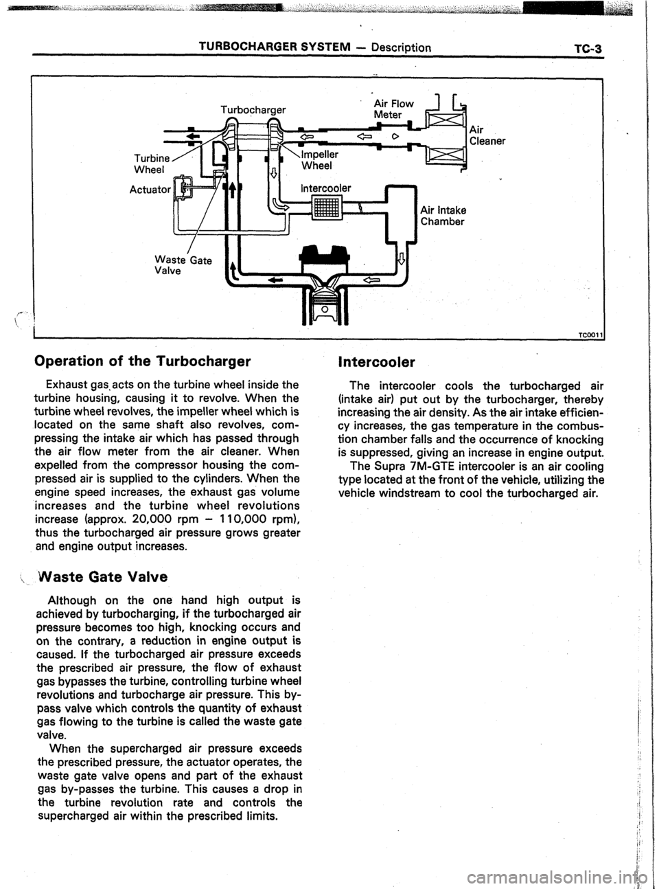
Operation of the Turbocharger
Waste’Gate
Valve Intercooler
Air intake
Chamber
Exhaust gas.acts on the turbine wheel inside the
turbine housing, causing it to revolve. When the
turbine wheel revolves, the impeller wheel which is
located on the same shaft also revolves, com-
pressing the intake air which has passed through
the air flow meter from the air cleaner. When
expelled from the compressor housing the com-
pressed air is supplied to the cylinders. When the
engine speed increases, the exhaust gas volume
increases and the turbine wheel revolutions
increase (approx. 20,000 rpm - 110,000 rpm),
thus the turbocharged air pressure grows greater
and engine output increases.
I, Waste Gate Valve
Although on the one hand high output is
achieved by turbocharging, if the turbocharged air
pressure becomes too high, knocking occurs and
on the contrary, a reduction in engine output is
caused. If the turbocharged air pressure exceeds
the prescribed air pressure, the flow of exhaust
gas bypasses the turbine, controlling turbine wheel
revolutions and turbocharge air pressure. This by-
pass valve which controls the quantity of exhaust
gas flowing to the turbine is called the waste gate
valve.
When the supercharged air pressure exceeds
the prescribed pressure, the actuator operates, the
waste gate valve opens and part of the exhaust
gas by-passes the turbine. This causes a drop in
the turbine revolution rate and controls the
supercharged air within the prescribed limits.
Intercooler
The intercooler cools the turbocharged air
(intake air) put out by the turbocharger, thereby
increasing the air density. As the air intake efficien-
cy increases, the gas temperature in the combus-
tion chamber falls and the occurrence of knocking
is suppressed, giving an increase in engine output.
The Supra 7M-GTE intercooler is an air cooling
type located at the front of the vehicle, utilizing the
vehicle windstream to cool the turbocharged air.