1987 TOYOTA CELICA engine oil
[x] Cancel search: engine oilPage 6 of 346
IN-4 Identification Information,
INTRODUCTION - General Repair Instructions
IDENTIFICATION INFORMATION
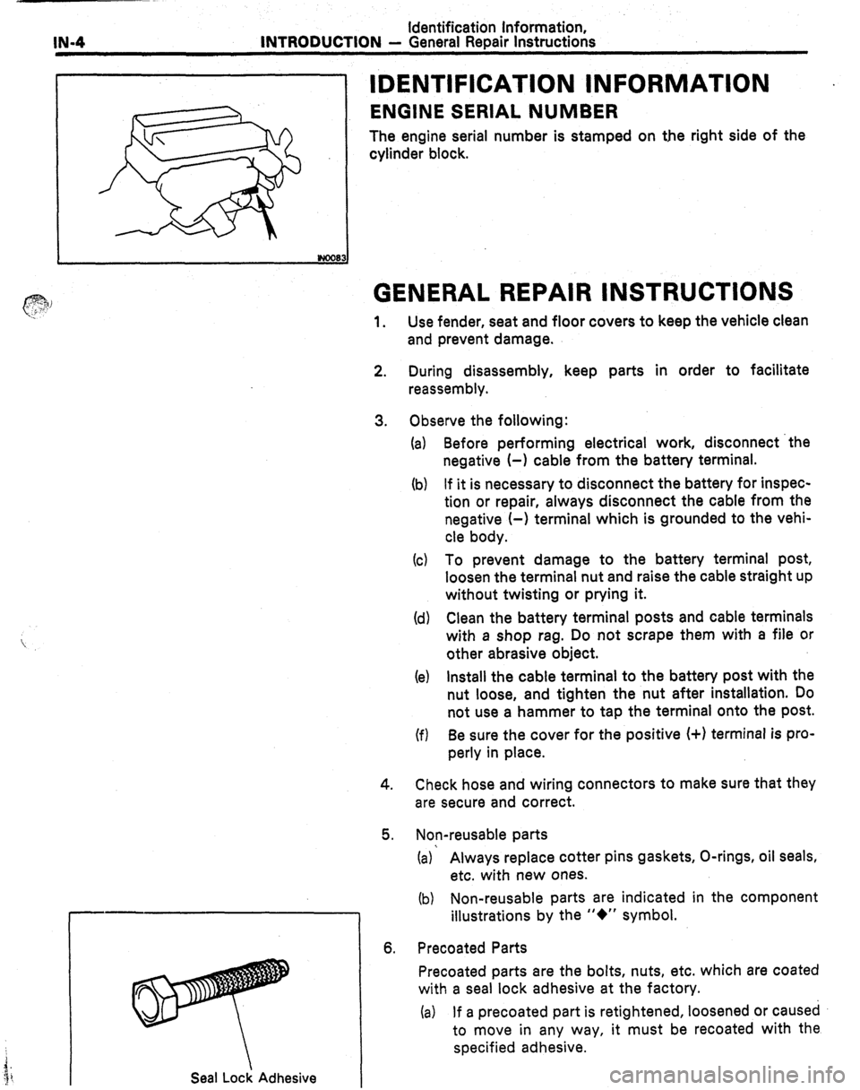
ENGINE SERIAL NUMBER
The engine serial number is stamped on the right side of the
cylinder block.
Seal Lock Adhesive
GENERAL REPAIR INSTRUCTIONS
1. Use fender, seat and floor covers to keep the vehicle clean
and prevent damage.
2.
3. During disassembly, keep parts in order to facilitate
reassembly.
Observe the following:
(a)
(b) Before performing electrical work, disconnect ‘the
negative (-1 cable from the battery terminal.
If it is necessary to disconnect the battery for inspec-
tion or repair, always disconnect the cable from the
negative (-) terminal which is grounded to the vehi-
cle body.
(c) To prevent damage to the battery terminal post,
loosen the terminal nut and raise the cable straight up
without twisting or prying it.
(d) Clean the battery terminal posts and cable terminals
with a shop rag. Do not scrape them with a file or
other abrasive object.
(e)
(f) Install the cable terminal to the battery post with the
nut loose, and tighten the nut after installation. Do
not use a hammer to tap the terminal onto the post.
Be sure the cover for the positive (+I terminal is pro-
perly in place.
4.
5. Check hose and wiring connectors to make sure that they
are secure and correct.
Non-reusable parts
(a)’ Always replace cotter pins gaskets, O-rings, oil seals,
etc. with new ones.
(b) Non-reusable parts are indicated in the component
illustrations by the “+” symbol.
6. Precoated Parts
Precoated parts are the bolts, nuts, etc. which are coated
with a seal lock adhesive at the factory.
(a) If a precoated part is retightened, loosened or caused
to move in any way, it must be recoated with the
specified adhesive.
Page 23 of 346
. COOLING SYSTEM - Description
co;3
RESERVOIR TANK
The reservoir tank is used to catch coolant
which overflows the cooling systein as a result of
volumetric expansion when the coolant is heated.
The coolant in the reservoir tank returns to the
radiator when the coolant temperature drops, thus
keeping the radiator full at all times and avoiding
needless coolant loss. Check the reservoir tank
level to learn if the coolant needs to be rep-
lenished.
WATER PUMP
The water pump is used for forced circulation of
coolant through the cooling system. It is mounted
on the front of the cylinder block and driven by a
V-ribbed belt,
THERMOSTAT I The cooling system is composed of the water
jacket (inside the cylinder block and cylinder head),
radiator, water pump, thermostat, cooling fan,
hoses and other components.
Coolant which is heated in the water
jacket is
pumped to the radiator, through which a cooling
fan blows air to cool the coolant as it passes
through. Coolant which has been cooled is then
sent back to the engine by the water pump, where
it cools the engine.
The water jacket is a network of channels in the
shell of the cylinder block and cylinder head
through which coolant passes. It is designed to
provide adequate cooling of the cylinders are com-
bustion chambers which become the hottest dur-
ing engine operation.
F(/ “ IATOR
The radiator performs the function of cooling
the coolant which has passed through the water
jacket and become hot, and is mounted in the front
of the vehicle. The radiator consists of an upper
tank and ‘lower tank, and a core which connects
the two tanks. The upper tank contains the inlet for
coolant from the water jacket and the filter inlet. It
also has a hose attached through which excess
coolant or steam can flow. The lower tank contains
the outlet for coolant and the drain cock. The core
contains many tubes through which coolant flows
from the upper tank to the lower tank as well as
cooling fins which radiate heat away from the coo-
lant in the tubes. The air sucked through the radia-
tor by cooling fan, as well as the wind generated
by the vehicle’s travel, passes through the radia-
tor, cooling it. Models with automatic transmission
incrl*-le an automatic transmission fluid cooler built
in:.
.le lower tank of the radiator.
RADIATOR CAP
The radiator cap is a pressure type can which
seals the radiator, resulting in pressurization of the
radiator as the coolant expands. The pressuriza-
tion prevents the coolant from boiling even when
the coolant temperature exceeds 100°C. A relief
valve (pressurization valve) and a vacuum valve
(negative pressure valve) are built into the radiator
zap. The relief valve opens and lets steam escape
:hrough the overflow pipe when the pressure
3enerated inside the cooling system exceeds the
imit (coolant temperature:
110 - 1 20°C, (230
- 248”F), pressure; 0.3 - 1 .O kg/cmz, (4.3 - 14.2
)si, 29.4 - 98.1 kPa). The vacuum valve opens to
3ljeviate the vacuum which develops in the coolant
system after the engine is stopped and the coolant
emperature drops. The valve’s opening allows the
)ressure in the cooling system to return to the
Qclant in the reservoir tank. The thermostat has a wax type and is mounted
in the. water outlet housing. The thermostat
includes a type of automatic valve operated by
fluctuations in the coolant temperature. This valve
closes when the coolant temperature drops, pre-
venting the circulation of coolant through the
engine and thus permitting the engine to warm up
rapidly. The valve opens when the coolant tem-
perature has risen, allowing the circulation of coo-
lant. Wax inside the thermostat expands when
heated and contracts when cooled. Heating the
wax thus generates pressure which overpowers
the force of the spring which keeps the valve
closed, thus opening the valve. When the wax
cools, its contraction causes the force of the
spring to take effect once more, closing the valve.
The thermostat in this engine operates at a tem-
perature of 88”C(19O”F).
I
I
Page 25 of 346
COOLING SYSTEM i Check and Replacement of Engine Coolant
co-5
._
CHECK AND REPLACEMENT OF
ENGINE COOLANT
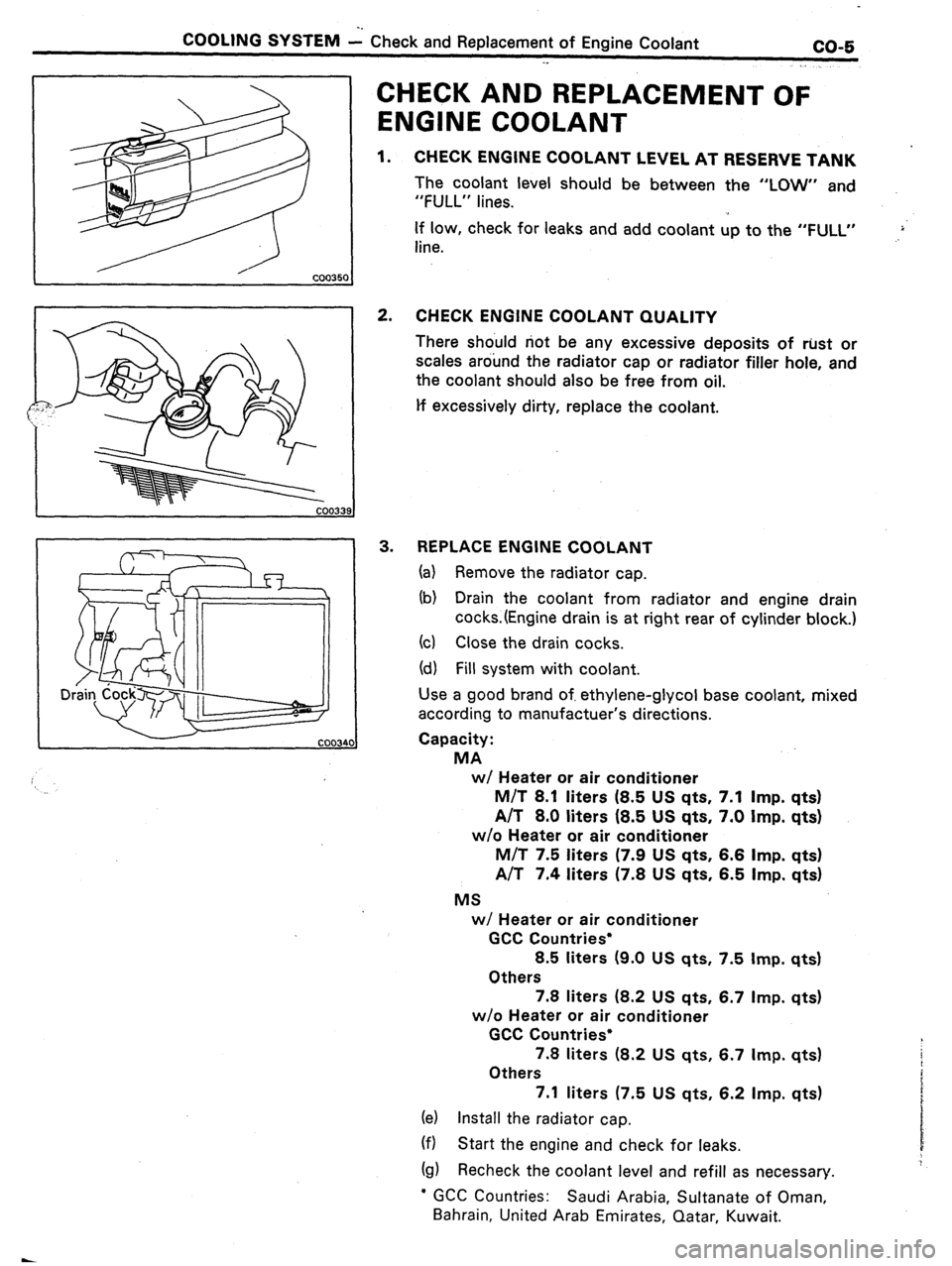
1. CHECK ENGINE COOLANT LEVEL AT RESERVE TANK
The coolant level should be between the “LOW” and
“FULL” lines.
If low, check for leaks and add coolant up to the “FULL”
line. .,>‘
2. CHECK ENGINE COOLANT QUALITY
There should not be any excessive deposits of rust or
scales around the radiator cap or radiator filler hole, and
the coolant should also be free from oil.
lf excessively dirty, replace the coolant.
3. REPLACE ENGINE COOLANT
(a) Remove the radiator cap.
(b) Drain the coolant from radiator and engine drain
cocks.(Engine drain is at right rear of cylinder block.)
(cl Close the drain cocks.
(d) Fill system with coolant.
Use a good brand of. ethylene-glycol base coolant, mixed
according to manufactuer’s directions.
Capacity:
MA
w/ Heater or air conditioner
M/T 8.1 liters (8.5 US qts. 7.1 Imp. qts)
A/T 8.0 liters (8.5 US qts, 7.0 Imp. qts)
w/o Heater or air conditioner
M/T 7.5 liters (7.9 US qts, 6.6
Imp. qts)
A/T 7.4 liters (7.8 US qts, 6.5 Imp. qts)
MS
w/ Heater or air conditioner
GCC Countries*
8.5 liters (9.0 US qts, 7.5 Imp. qts)
Others
7.8 liters (8.2 US qts, 6.7 Imp. qts)
w/o Heater or air conditioner
GCC Countries*
7.8 liters (8.2 US qts, 6.7 Imp. qts)
Others
7.1 liters (7.5 US qts, 6.2 Imp. qts)
(e) Install the radiator cap.
(f) Start the engine and check for leaks.
(g) Recheck the coolant level and refill as necessary.
l GCC Countries: Saudi Arabia, Sultanate of Oman,
Bahrain, United Arab Emirates, Qatar, Kuwait.
Page 41 of 346
EFI SYSTEM
- Precautions, Inspection Precautions
FI-7
PRECAUTIONS
._
1. Before working on the fuel system, disconnect the
negative terminal from the battery.
NOTE: Any diagnosis code retained by the computer will
be erased when the battery terminal is removed.
Therefore, if necessary, read the diagnosis before
removimg the battery terminal.
2. Do not smoke or work near an open flame when work-
ing on the fuel system.
3. Keep gasoline off rubber or leather parts.
INSPECTION PRECAUTl.ONS
MAINTENANCE PRECAUTIONS
1. INSURE CORRECT ENGINE TUNE-UP
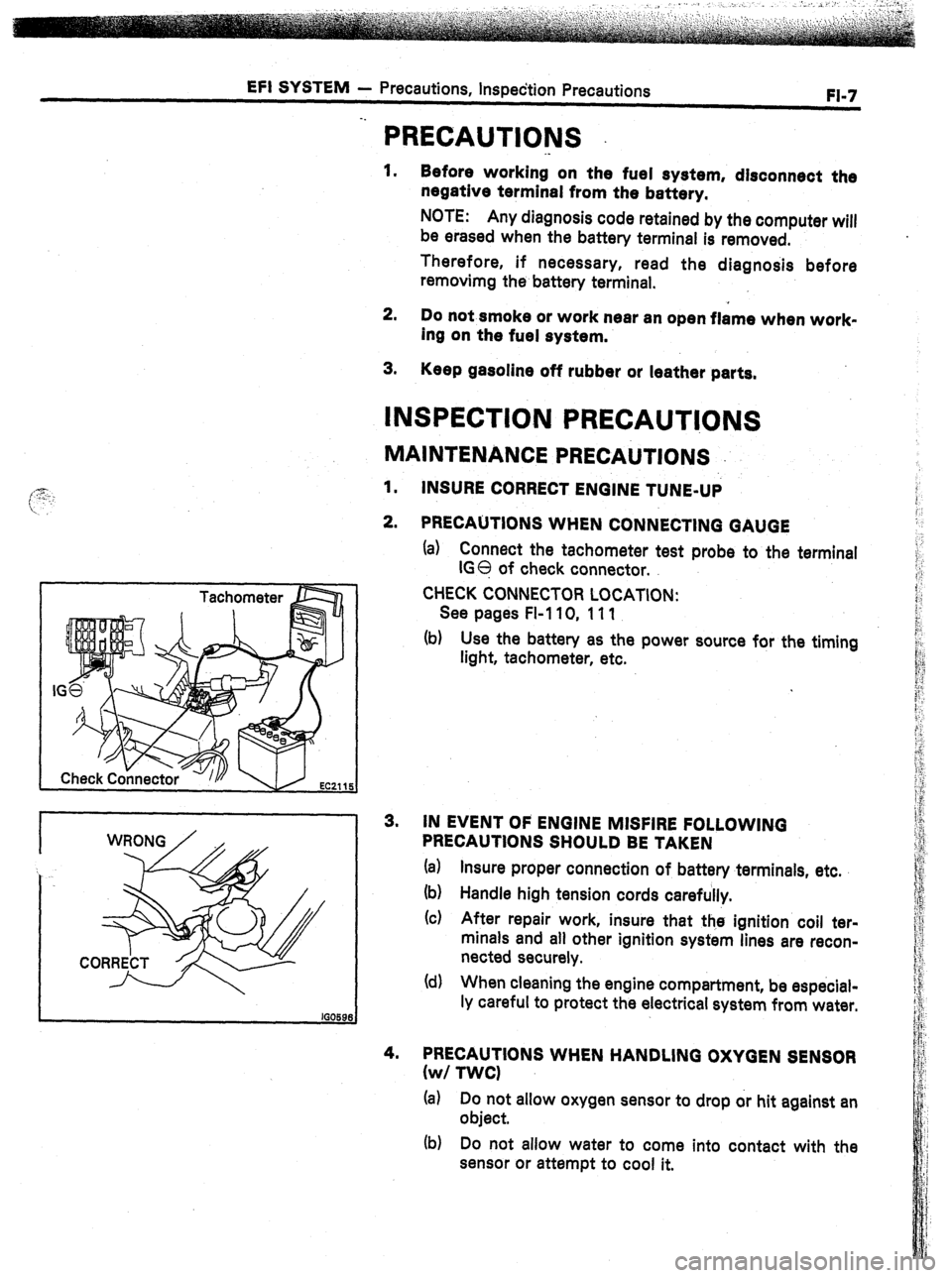
2. PRECAUTIONS WHEN CONNECTING GAUGE
(a) Connect the tachometer test probe to the terminal
IGO of check connector.
CHECK CONNECTOR LOCATION:
See pages FI-110, 111
(b) Use the battery as the power source for the timing
light, tachometer, etc.
3. IN EVENT OF ENGINE MISFIRE FOLLOWING
PRECAUTIONS SHOULD BE TAKEN
(a) Insure proper connection of battery terminals, etc.
(b) Handle high tension cords carefully.
(c) After repair work, insure that the ignition coil ter-
minals and all other ignition system lines are recon-
nected securely.
(d) When cleaning the engine compartment, be especial-
ly careful to protect the electrical system from water.
4. PRECAUTIONS WHEN HANDLING OXYGEN SENSOR
(w/ TWCI
(a) Do not allow oxygen sensor to drop or hit against an
object.
(b) Do not allow water to come into contact with the
sensor or attempt to cool it.
Page 42 of 346
-8 EFI SYSTEM -.- Inspection Precautions
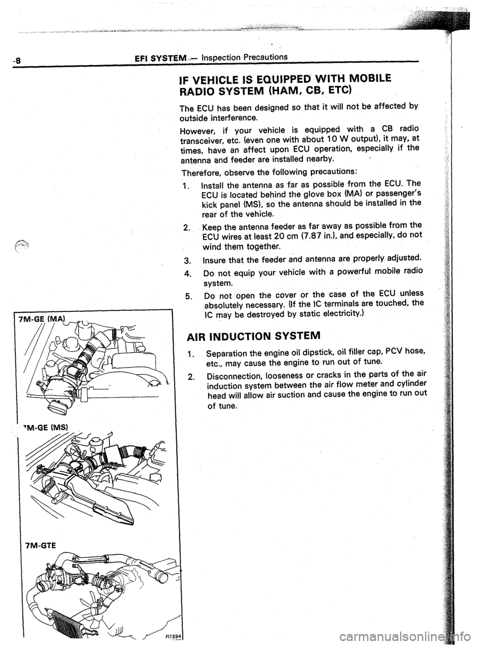
IF VEHICLE IS EQUIPPED WITH MOBILE
RADIO SYSTEM (HAM, CB, ETC)
The ECU has been designed so that it will not be affected by
outside interference.
However, if your vehicle is equipped with a CB radio
transceiver, etc. (even one with about 10 W output), it may, at
times, have an affect upon ECU operation, especially if the
antenna and feeder are installed nearby.
Therefore, observe the following precautions:
1. Install the antenna as far as possible from the ECU. The
ECU is located behind the glove box (MA) or passenger’s
kick panel (MS), so the antenna should be installed in the
rear of the vehicle.
2. Keep the antenna feeder as far .away as possible from the
ECU wires at least 20 cm (7.87 in.), and especially, do not
wind them together.
3. Insure that the feeder and antenna are properly adjusted.
4. Do not equip your vehicle with a powerful mobile radio
system.
Do not open the cover or the case of the ECU unless
absolutely necessary. (If the IC terminals are touched, the
. . .
IC may be destroyed by static electricity.1
AIR INDUCTION SYSTEM
1.
2. Separation the engine oil dipstick, oil filler cap, PCV hose,
etc., may cause the engine to run out of tune.
Disconnection, looseness or cracks in the parts of the air
induction system between the air flow meter and cylinder
head will allow air suction and cause the engine to run out
of tune.
TM-GE (MS)
7M-GTE
Page 45 of 346
EFI SYSTEM
- inspection Precautions
FI-11
I CORRECT i
Gro
Q * Delivery
Ring pipe
*
Black Ring
Delivew
Pipe -
O-Ring
-Grommet
3.
4.
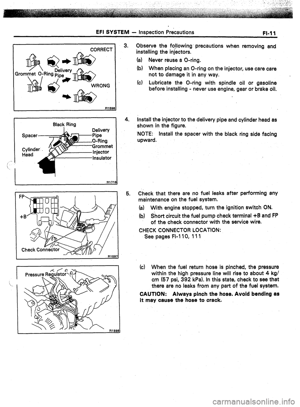
5. Observe the fo!lowing’ precautions when removing and
installing the injectors.
(a) Never reuse a O-ring.
(b) When placing an O-ring on the injector, use care care
not to damage it in any way.
(c) Lubricate the O-ring with spindle oil or gasoline
before installing - never use engine, gear or brake oil.
Install the injector to the delivery pipe and cylinder head as
shown in the figure.
‘NOTE: Install the spacer with the black ring side facing
upward.
Check that there are no fuel leaks after performing any
maintenance on the fuel system.
(a) With engine stopped, turn the ignition switch ON.
(b) Short circuit the fuel pump check terminal +B and FP
of the check connector with the service wire.
CHECK CONNECTOR LOCATION:
See pages FI-110, 111
(c) When the fuel return hose is pinched, the pressure
within the high pressure line will rise to about 4 kg/
cm (57 psi, 392 kPa). In this state, check to see that
there are no leaks from any part of the fuel system.
CAUTION: Always pinch the hose. Avoid bending as
it may cause the hose to crack.
Page 46 of 346
1-12 EFI SYSTEM - Troubleshooting’
FlO48
TROUBLESH~~TI~~G
. .
TROUBLESHOOTING HlhJTS
1. Engine troubles are usually not caused by the EFI system.
When troubleshooting, always first check the condition of
the other systems.
(a) Electronic source
0 Battery
0 Fusible links
0 Fuses
(b) Body ground
(cl Fuel supply
0 Fuel leakage
0 Fuel filter
0 Fuel pump
(d) Ignition system
0 Spark plug
0 High-tension cord
l Distributor (7M-GE) or cam position sensor (7M-
GTE)
0 Igniter and ignition coil
(e) Air induction system
0 Vacuum leaks
(f) Emission control system
0 PCV system
0 EGR system (w/ EGR)
(g) Others
l Ignition timing (ESA system)
0 Idle speed (ISC system)
-r
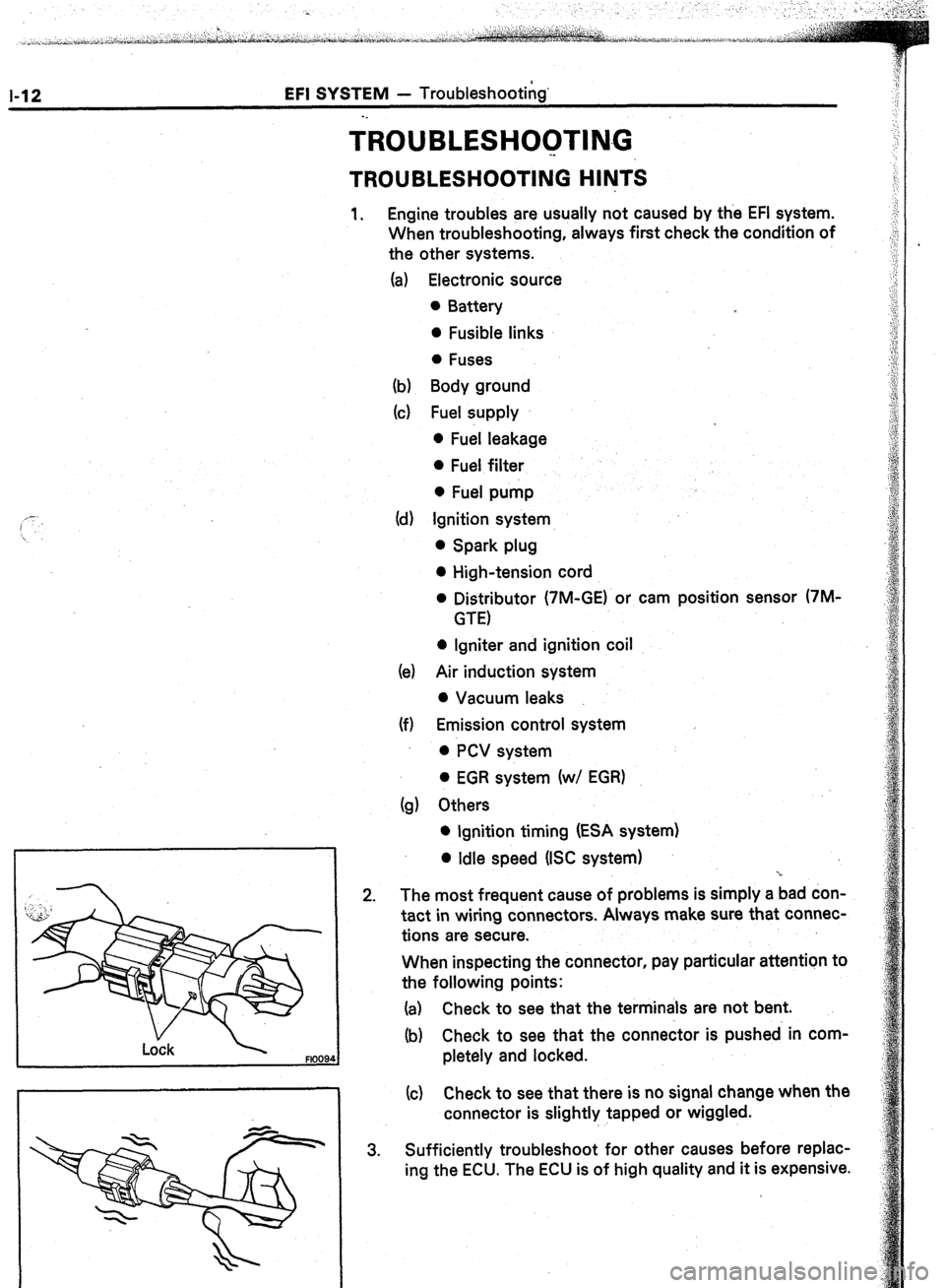
2. The most frequent cause of problems is simply a bad don-
tact in wiring connectors. Always make sure that connec-
tions are secure.
When inspecting the connector, pay particular attention to
the following points:
(a) Check to see that the terminals are not bent.
(b) Check to see that the connector is pushed in com-
pletely and locked.
(c) Check to see that there is no signal change when the
connector is slightly tapped or wiggled.
3. Sufficiently troubleshoot for other causes before replac-
ing the ECU. The ECU is of high quality and it is expensive.
Page 48 of 346
EFI SYSTEM - Troubleshootina
SYMPTOM - DIFFICULT TO START O-R NO START (CRANKS OK)
CHECK DIAGNOSIS SYSTEM
Check for output of diagnostic code.
(See page FI-26) Diagnostic code(s) (See pages FI-30,‘31,32)
Normal code
DOES ENGINE’START WITH
ACCELERATORPEDALDEPRESSED? OK ISC system
0) ISC valve
(2) Wiring connection
i NO I
CHECK FOR VACUUM LEAKS IN AIR I
BAD
INTAKE LINE
I OK
CHECK IGNITION SPARK ’
7M-GE (See page IO-61
7M-GTE (See page IG-12)
t OK
CHECKSPARKPLUGS
Plug gap:
7M-GE Conventional Tipped Type
0.8 ‘mm (0.031 In.)
7M-GE Platinum Tipped Type
: : 1.1 mm (0.043~in.)
.7M-GTE
0.8 mm (0.031 In.)
NOTE: Check compression pressure and
valve clearance if necessary.
OK CONTINUED ON PAGE FI-15
!
I
.
BAD 1. Oil filler cap
2. Oil dipstick
3. Hose connections
4. PCV hose
5. (w/ EGR)
EGR system - EGR valve stays open
1. High-tension cords
2. Distributor (‘IM-GE) or cam position
sensor (7M-GTE)
3. Ignition coil
4. Igniter
+
NO
BAD 1. Spark plugs
2. Compression pressure
Limit: 9.0 kg/cm2 (128 psi, 883 kPa)
at 250 rpm
3. Valve clearance (Cold)
STD: IN 0.16 - 0.25 mm
(0.008 - 0.010 in.)
EX 0.20 - 0.30 mm
(0.008 - 0.012 in.1
1. Injector - shorted or leaking
2. Injector wiring between resistor and
ECU shorted
3. Cold start injector - Leakage
(See page Fl-80)
4. Cold start injector time switch
(See page Fl-115)