1987 TOYOTA CELICA timing belt
[x] Cancel search: timing beltPage 24 of 346
co-4 CQOLING SYSTEM - Troubleshootmg
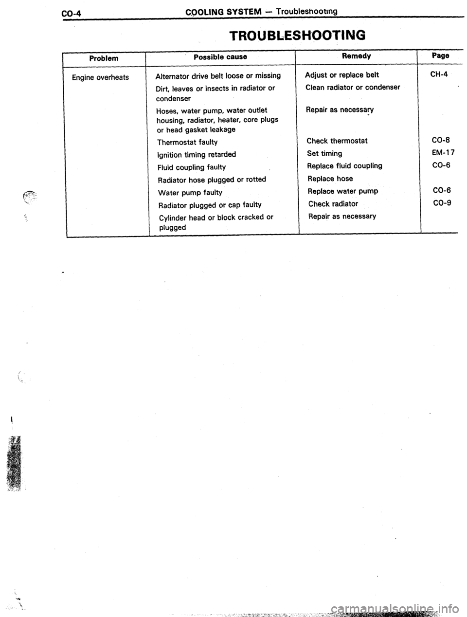
TROUBLESHOOTING
, Problem
Engine overheats Possible cause
Alternator drive belt loose or missing
Dirt, leaves or insects in radiator or
condenser
Hoses, water pump, water outlet
housing, radiator, heater, core plugs
or head gasket leakage
Thermostat faulty
Ignition timing
retarded
Fluid coupling faulty
Radiator hose plugged or rotted
Water pump faulty
Radiator plugged or cap faulty
Cylinder head or block cracked or
phwd Remedy
Adjust or replace belt
Clean radiator or condenser
Repair as necessary
Check thermostat
Set timing
Replace fluid coupling
Replace hose
Replace water pump
Check radiator
Repair as necessary Page
CH-4
CO-8
EM-l 7
CO-6
CO-6
co-9
Page 27 of 346
1.
2.
3.
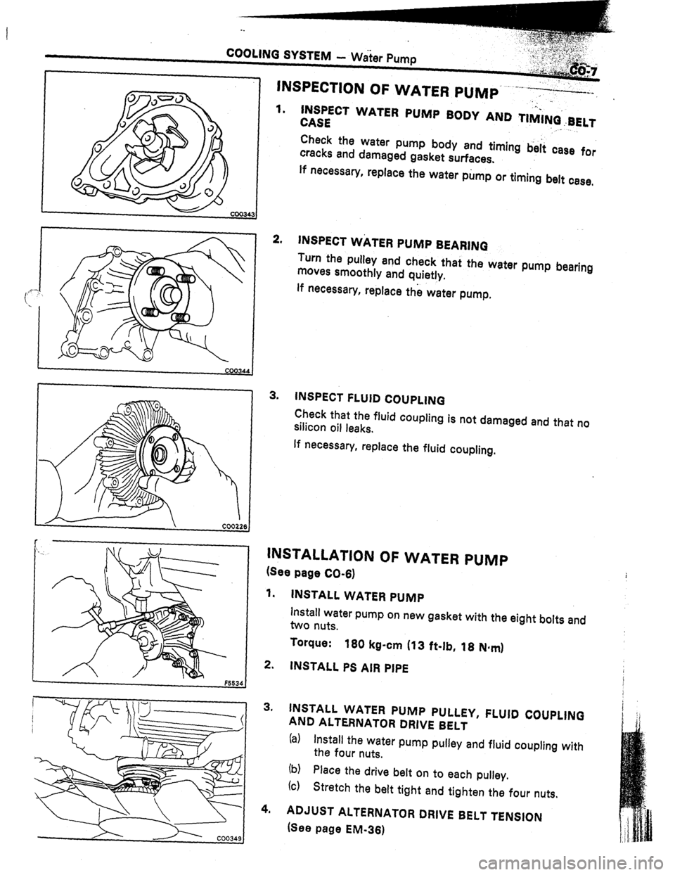
.._ INSPECT WATER PUMP BODY AND TIMI+BELT
CASE ” ._
Check the water pump body and timing b&i case for
cracks and damaged gasket surfaces.
If necessary, replace the water pump or timing belt case,
INSPECT WATER PUMP BEARINQ
Turn the pulley and check that the water pump bearing
moves smoothly and quietly.
lf necessary, replace the water pump,
INSPECT FLUID COUPLING
Check that the fluid coupling is not damaged and that no
silicon oil leaks.
If necessary, replace the fluid coupling.
INSTALLATION OF WATER PUMP
(See page CO-6)
1. INSTALL WATER PUMP
install water pump on new gasket with the eight bolts and
two nuts.
Torque:
160 kg-cm (13 ft-lb, 18 N*mI
2. INSTALL PS AIR PIPE
3. INSTALL WATER PUMP PULLEY, FLUID COUPLING
AND ALTERNATOR DRIVE BELT
(al Install the water pump pulley and fluid coupling with
the four nuts.
(b)
(c) Place the drive belt on to each pulley.
Stretch the belt tight and tighten the four nuts.
4. ADJUST ALTERNATOR DRIVE BELT TENSION
(See page EM-361
Page 163 of 346
-.
EM-1
I
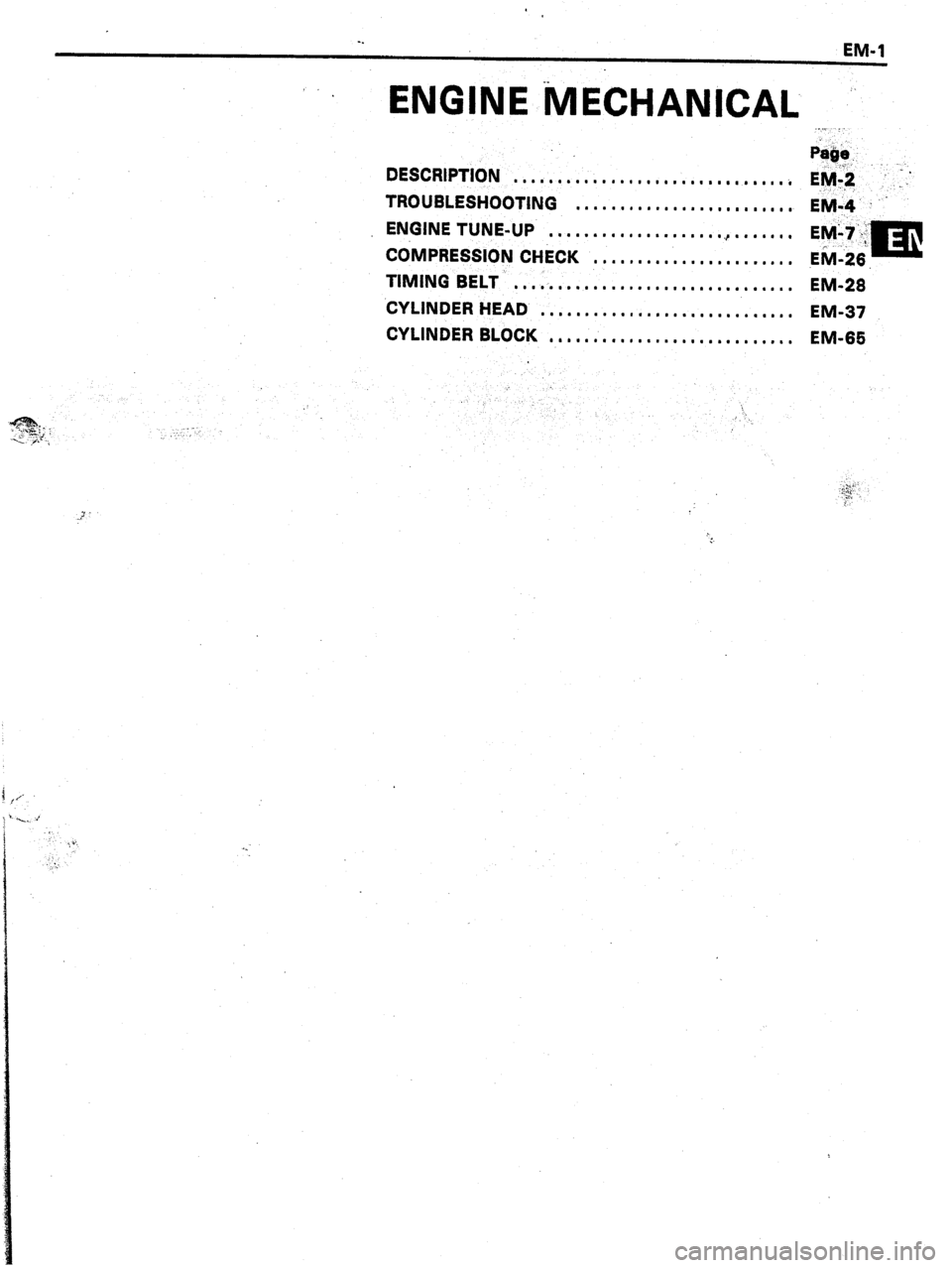
ENGINE MECHANICAL .’ ../_ :.
F&e.
DESCRIPTION
. . . ..1........111.......~....~.~ E+ -;.’
TROUBLESHOOTING
. . . . . . . . . . . . . . . . n . ma m I. I.
EM-4’ ”
ENGINE TUNE-UP
. . . . . . . . . . . . ..~......~.......
COMPRESSION CHECK
s e . . . . . . . . . . . . . , . . . . . . .
TIMING BELT
,,,..,....................*.*...
EM-28
CYLINDER HEAD
. . . . . . . . . . . . . . ..*............
EM-37
CYLINDER BLOCK
1”1......1...............,..
EM-66
Page 165 of 346
ENGINE MECHANICAL -, Description
EM-3
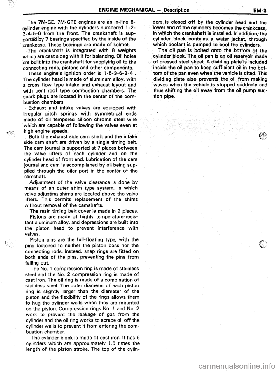
The 7M-GE, 7M-GTE engines are an in-line 6-
cylinder engine with the cylinders numbered l-2-
3-4-5-6 from the front. The crankshaft is sup-
ported by 7 bearings specified by the inside of the
crankcase. These bearings are made of kelmet.
.The crankshaft is integrated with 8 weights
which are cast along with it for balancing. Oil holes
‘are built into the crankshaft for supplying oil to the
connecting rods, pistons and other components.
These engine’s ignition order is l-5-3-6-2-4 .
The cylinder head is made of aluminum alloy, with
a cross flow type intake and exhaust layout and
with pent roof type combustion chambers. The
spark plugs are located in the center of the com-
bustion chambers.
Exhaust and intake valves are equipped with
irregular pitch springs with symmetrical ends
made of oil tempered silicon chrome steel wire
which are capable of following the valves even at
,high engine speeds.
Both the exhaust side cam shaft and the. intake
side cam shaft are driven by a single timing belt.
The cam journal is supported at 7 places between
the valve lifters of each cylinder and on the
cylinder head of front end. Lubrication of the cam
journal and cam is accomplished by oil being sup-
plied through the oiler port in the center of the
camshaft.
Adjustment of the valve clearance is done by
means of an outer shim type system, in which
valve adjusting shims are located above the valve
lifters. This permits replacement of the shims
without removal of the camshafts.
The resin timing belt cover is made in 2 pieces.
Pistons are made of highly temperature-resis-
tant aluminum alloy, and depressions are built into
the piston head to prevent interference with
valves.
Piston pins are the full-floating type, with the
pins fastened to neither the piston boss nor the
connecting rods. Instead, snap rings are fitted on
both ends of the pins, preventing the pins from
falling out.
The No. 1 compression ring is made of stainless
steel and the No. 2 compression ring is made of
cast iron. The oil ring is made of a combination of
stainless steel. The outer diameter of each piston
ring is slightly larger than the diameter of the
piston
and the flexibility of the rings allows them
to hug the cylinder walls when they are mounted
on the piston. Compression rings No. 1 and No. 2
work to prevent the leakage of gas from the
cylinder and the oil ring works to scrape oil off the
cylinder walls to prevent it from entering the com-
bustion chamber.
The cylinder block is made of cast iron. It has 6
cylinders which are approximately 1.6 times the
length of the piston stroke. The top of the cylin- ders is closed off by the cylinder head and the
lower end of the cylinders becomes the crankcase,
in which the crankshaft is installed. In addition,- the
cylinder block contains a water jacket, through
which coolant is pumped to cool the cylinders.
The .oil pan is bolted onto the botiom of the
cylinder block. The oil pan is an oil reservoir made .
of pressed steel sheet. A dividing plate’is included
-inside the oil pan to keep sufficient oil in the bot-
tom of the pan even when the vehicle is tilted. This
dividing plate also prevent5 the oil from making
waves when the vehicle is stopped suddenly and
thus shifting the oil away from the oil pump suc-
tion pipe.
Page 171 of 346
ENGINE MECHANICAL - Engine Tune-up
3.
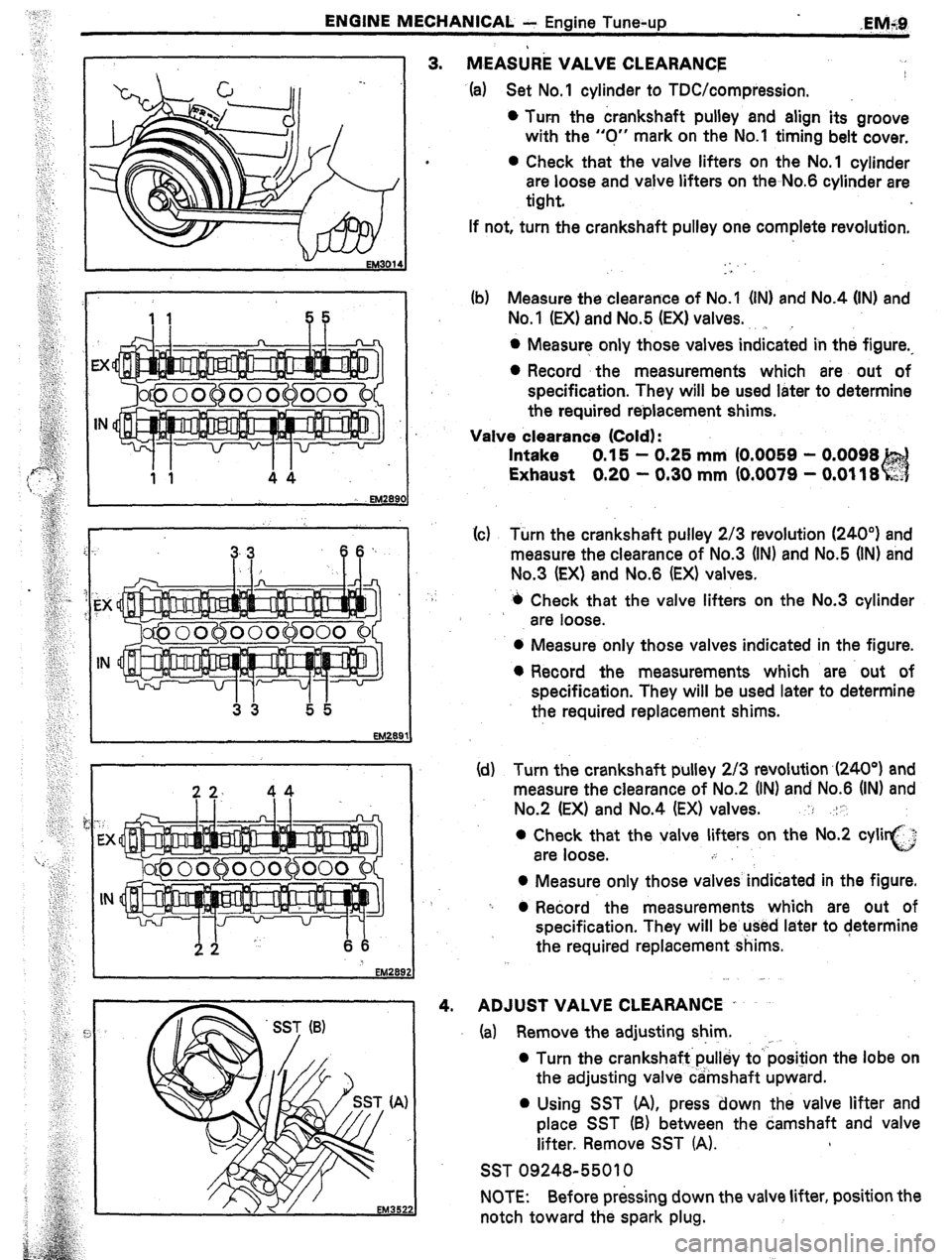
* MEA&E VALVE CLEARANCE I
4. (a) Set No.1 cylinder to TDC/compression.
l Turn the crankshaft pulley and align its groove
with the “0” mark on the No.1 timing belt cover,
l Check that the valve lifters on the No.1 cylinder
are loose and valve lifters on the No.6 cylinder are
tight.
If not, turn the crankshaft pulley one complete revolution.
. .
. .
(b) Measure the clearance of No.1 (INI and No.4 (IN) and
No.1 (EX) and No.5 (EX) valves.
. . . .
l Measure only those valves indicated in the figure.,
0 Record the measurements which are. out of
specification. They will be used later to determine
the required reblacement shims.
Valve clearance (Cold) :
Intake 0.15 - 0.25 mm (0.0059 - 0.0098
Exhaust 0.20 - 0.30 mm (0.0079 - 0.0118
(c(c) Turn the crankshaft pulley 2/3 revolution (240”) and
measure the clearance of No.3 (IN) and No.5 (IN) and
No.3 (EX) and No.6 (EX) valves.
4 Check that the valve lifters on the No.3 cylinder
are loose.
0 Measure only those valves indicated in the figure.
l Record the measurements which are out of
specification. They will be used later to determine
the required replacement shims.
(d) Turn the crankshaft pulley 2/3 revolution ,(240°) and
measure the clearance of No.2 (IN) and No.6 (IN) and
No.2 (EX) and No.4 (EX) valves. : .-:1’.
0 Check that the valve lifters on the No.2 cyli i,:..?
are loose. c
.i
0 Measure only those valves indidated in the figure.
-I 0 Record the measurements which are out of
specification. They will be used later to determine
the required replacement shims.
ADJUST VALVE CLEARANCE .
(a) Remove the adjusting shim. ,
0 Turn the crankshaft.pulley to’ position the lobe on
the adjusting valve camshaft upward.
0 Using SST (A), press down the valve lifter and
place SST (B) between the camshaft and valve
lifter. Remove SST (A).
SST 09248-55010
NOTE: Before pressing down the valve lifter, position the
notch toward the spark plug.
Page 190 of 346
EM-28
ENGINE MECliANICAL - Titiingj Belt.
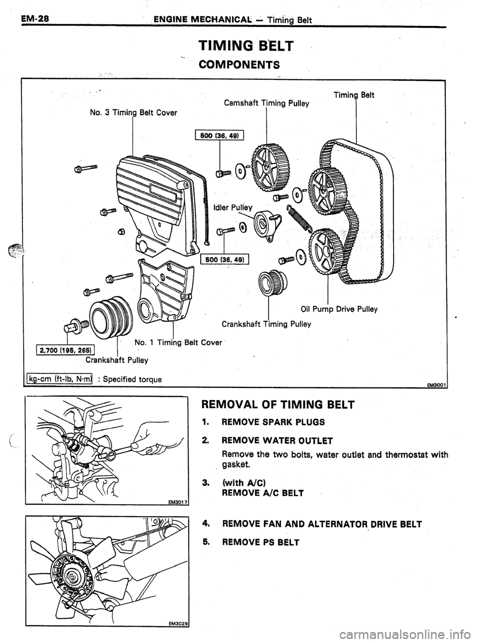
TIMING B’ELT
-.
COMPONENTS
No. 3 Timing Belt Cover Camshaft Timing Pulley
I I ImIng oen
I
Crankshaft Pulley
kg-cm (ft-lb, N-ml : Specified torque
EM30f 31
REMOVAL OF TIMING BELT
1.
REMOVE SPARK PLUGS
2. REMOVE WATER OUTLET
Remove the two bolts, water outlet and thermostat with
. gasket.
3. .(with A/C)
REMOVE A/C BELT
4. REMOVE FAN AND ALTERNATOR DRIVE BELT
5.
REMOVE PS BELT
Page 191 of 346
ENGINE MECHANICAL, k Timi’ng Belt-
~@Jli&%J
,_... - ,. _, ’
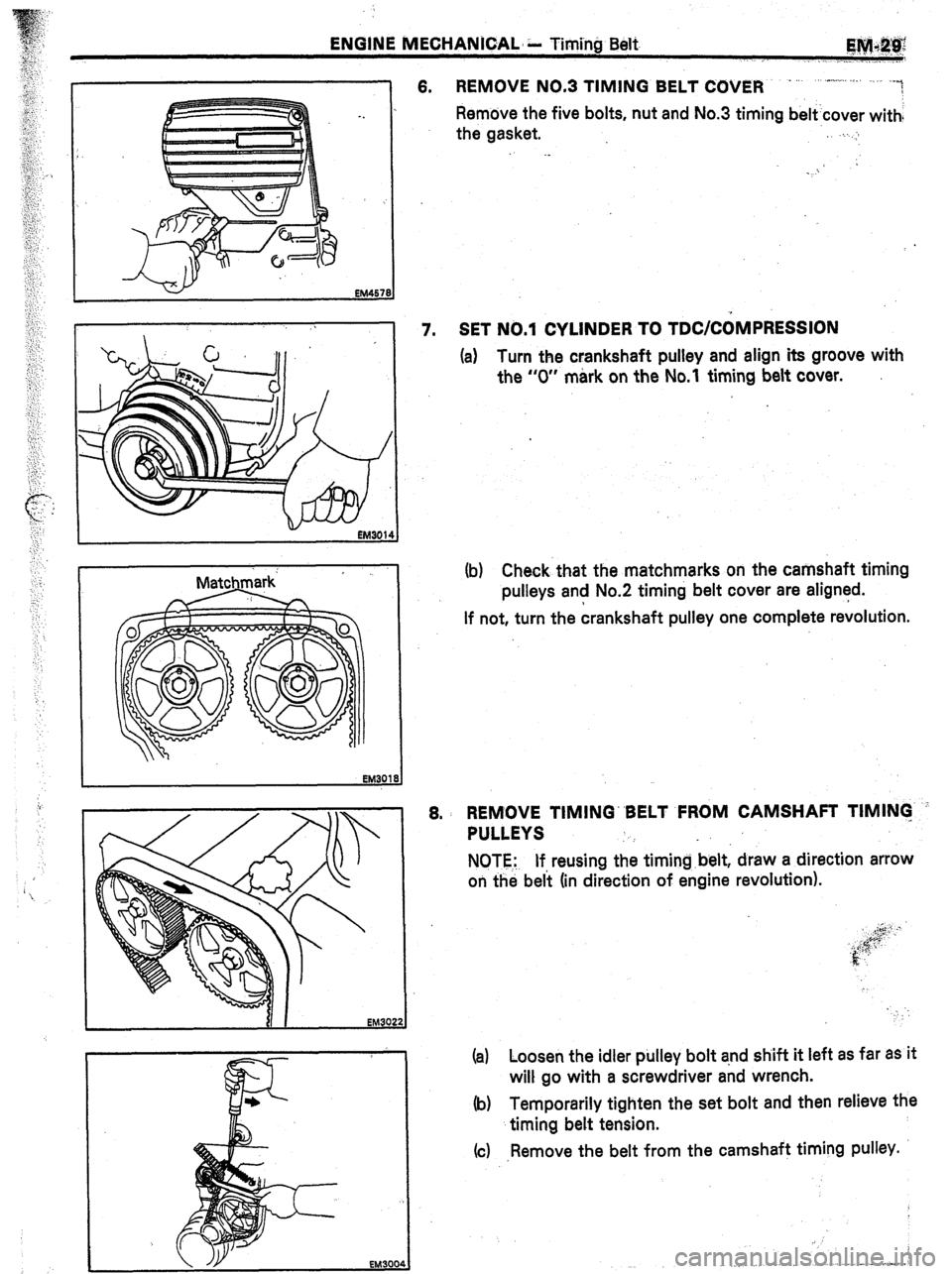
I 6. REMOVE NO.3 TIMING BELT COVER - ~ .-,.,.,.... ./. -~
/
Remove the five bolts, nut and No.3 timing belt’cover with:
the gasket. .,..,I
’ 7. SET NO.1 CYLINDER TO TDCICOMPRESSION
(a) Turn the crankshaft pulley and align its groove with
the “0” mark on the No.1 timing belt cover.
EM300d
(b) Check that the matchmarks on the camshaft timing
pulleys and No.2 timing belt cover are aligned.
If not, turn the crankshaft pulley one complete revolution.
8. REMOVE TIMING“BELT FROM CAMSHAFT TIMING -’
PULLEYS
NOTE.: If reusing the timingbelt, draw a direction arrow
on the bel’t (in direction of engine revolution).
(a) Loosen the idler pulley bolt and shift it left as far as it
will go with a screwdriver and wrench.
(b) Temporarily tighten the set bolt and then relieve the
timing belt tension.
(c) ,Remove the belt from the camshaft timing pulley.
. .
Page 192 of 346
EM-30 ENGINE MECHANICAL - Timing Belt
EM290t
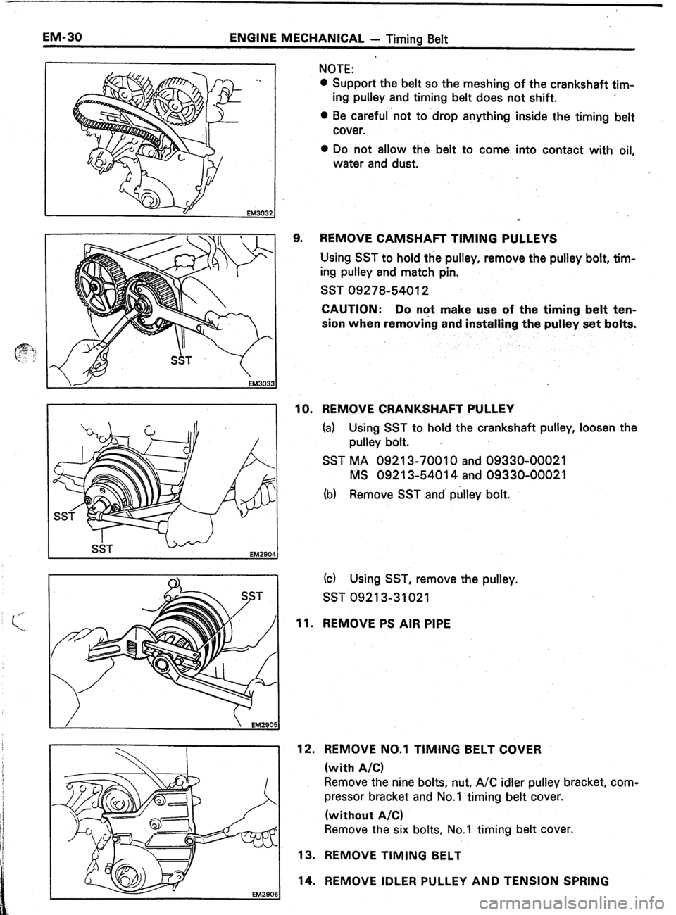
9. NOTE:
l Support the belt so the meshing of the crankshaft tim-
ing pulley and timing belt does not shift.
0 Be careful”not to -drop anything inside the timing belt
cover.
0 Do not allow the- belt to come into contact with oil,
water and dust.
REMOVE CAMSHAFT TIMING PULLEYS
Using S.ST to hold the pulley, remove the pulley bolt, tim-
ing pulley and match pin.
SST 09278-54012
CAUTION: Do nqt make use of the timing belt ten-
sion when removing and installing the pulley set bolts.
10. REMOVE CRANKSHAFT PULLEY
(a) Using SST to hold the crankshaft pulley, loosen the
pulley bolt.
SST MA 09213-70010 and 09330-00021
MS 09213-54014 and 09330-00021
(b) Remove SST and’ pulley bolt.
(cl Using SST, remove the pulley.
SST 09213-31021
11. REMOVE PS AIR PIPE
12. REMOVE NO.1 TIMING BELT COVER
(with A/C)
Remove the nine bolts, nut, A/C idler pulley bracket, com-
pressor bracket and No.1 timing belt cover.
(without A/C)
Remove the six bolts, No.1 timing belt cover.
13. REMOVE TIMING BELT
14. REMOVE IDLER PULLEY AND TENSION SPRING