1987 TOYOTA CELICA torque
[x] Cancel search: torquePage 4 of 346
IN-2 INTRODUiTlON - How to Use This Manual
._. ._. -,-. . .
.
HOW TO USE THIS MANUAL
To assist you in finding your way through this manual, the Set-
tion Title and major heading are given at the top of every page.
An INDEX is provided on the 1 st page of each section to guide
YOU to the item to be repaired.
At the beginning of each section, PRECAUTIONS are given
that pertain to al/repair operations contained in that section. Read these precautions before starting any repair task.
TROUBLESHOOTING tables are included for each system to
help you diagnose the system problem and find the cause. The
repair for each possible cause is referenced in the remedy
COI-
umn to quickly lead you to the solution.
REPAIR PROCEDURES
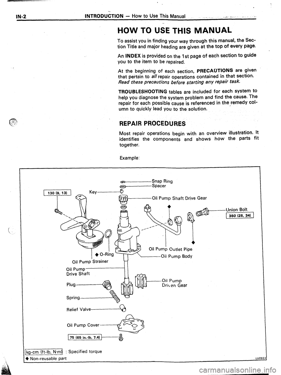
Most repair operations begin with an overview illustration. lt
identifies the components and shows how the
patiS fit
together.
Example:
Oil Pump
Shaft Drive Gear
Oil Pump Outlet Pipe
Oil Pump
Strainer
Drive Shaft
Relief Valve------Q
Oil Pump Cover------&
75 (65 in.-lb, 7.4)
-Union Bolt
(1
cg-cm (ft-lb, N.m : Specified torque
) Non-reusable part
LUO5
Page 5 of 346
INTROkJCT-iON - How to Use This Manual
I IN-3
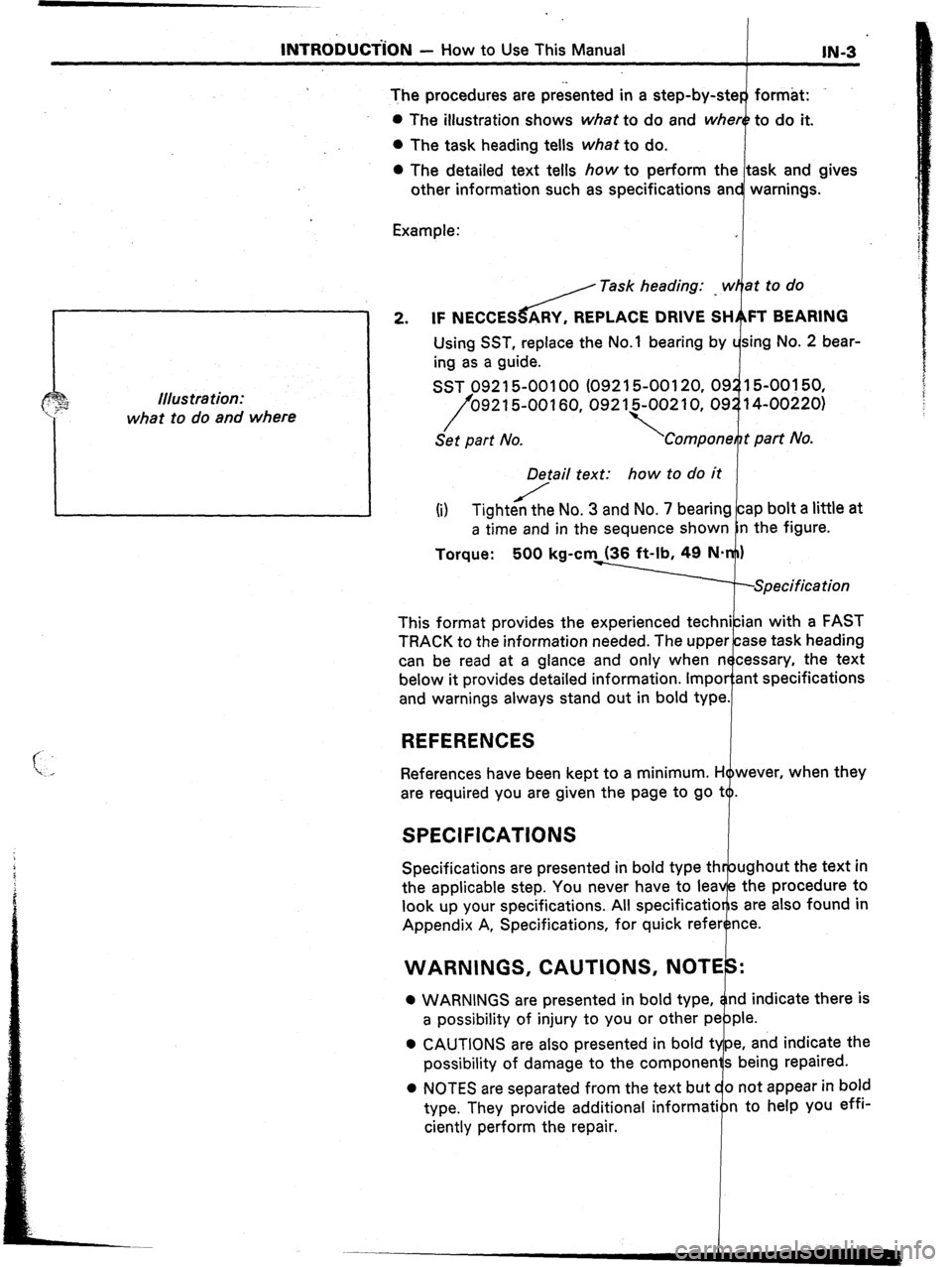
The procedures are presented in a step-by-ster format:
0 The illustration shows what to do and where to do it.
0 The task heading tells what to do.
0 The detailed text tells how to perform the task and gives
other information such as specifications and warnings.
Example:
J / Task heading: _ w at to do
tllus tra tion:
what to do and where 2. IF NECCESdY, REPLACE DRIVE SH FT BEARING
Using SST, replace the No.1 bearing by sing No. 2 bear-
ing as a guide.
SST 092 15-00100 (092 15-00120, 09 15-00150,
/ 092 1500160,092 15-002 10, 09 14-00220)
Set part No.
i Compone t part No.
D&/ail text: how to do it
(i) Tightecthe No. 3 and No. 7 bearing cap bolt a little at
a time and in the sequence shown n the figure.
Torque: 500 kg-cm (36 ft-lb, 49 NW)
.-Specification
This format provides the experienced technician with a FAST
TRACK to the information needed. The upper case task heading
can be read at a glance and only when necessary, the text
below it provides detailed information. Impor:ant specifications
and warnings always stand out in bold type.
REFERENCES
References have been kept to a minimum. However, when they
are required you are given the page to go to.
SPECIFICATIONS
Specifications are presented in bold type
the applicable step. You never have to I
look up your specifications. All specifica
Appendix A, Specifications, for quick
WARNINGS, CAUTIONS, N
0 WARNINGS are presented in bold d indicate there is
a possibility of injury to you or ot
0 CAUTIONS are also presented in bold
possibility of damage to the compone
0 NOTES are separated from the text
type. They provide additional infor
ciently perform the repair.
Page 7 of 346
INTRODUCTION - General Repair Instructions
IN-S
(b) Recoating of Precoated Parts
(1) Clean off the old adhesive from the part’s
threads.
(2) Dry with compressed air.
(3) Apply the specified seal lock adhesive to the
part’s threads.
(c) Precoated parts are indicated in the component
illustrations by the “*” symbol.
7. When necessary, use a sealer or gaskets to prevent leaks.
8. Carefully observe all specifications for bolt torques.
Always use a torque wrench.
9. Use of special service tools (SST) and special service
materials (SSM) may be required, depending on the nature
of the repair. Be sure to use SST and SSM where specified
and follow the proper work procedure. A list of SST and
SSM can be found at the back of this manual.
10. When replacing fuses, be sure the new fuse is the correct
amperage. DO NOT exceed the fuse amp rating or use one
of a lower rating.
11. Care must be taken when jacking up and supporting the
vehicle. Be sure to lift and support the vehicle at the
proper locations.
(a) If the vehicle is to be jacked up only at the front or
rear end, be sure to block the wheels in order to
ensure safety.
(b) After the vehicle is jacked up, be sure to support it on
stands. It is extremely dangerous to do any work on
the vehicle raised on a jack alone, even for a small job
that can be finished quickly.
WRONG
CORRECT 12. Observe the following precautions to avoid damaging the
parts:
(a) Do not open the cover or the case of the ECU unless
absolutely necessary. (If the IC terminals are touched,
the IC may be destroyed by static electricity.)
(b) Be careful not to drop electrical components, such as
sensors or relays. If they are dropped on a hard floor,
they should be replaced and not reused.
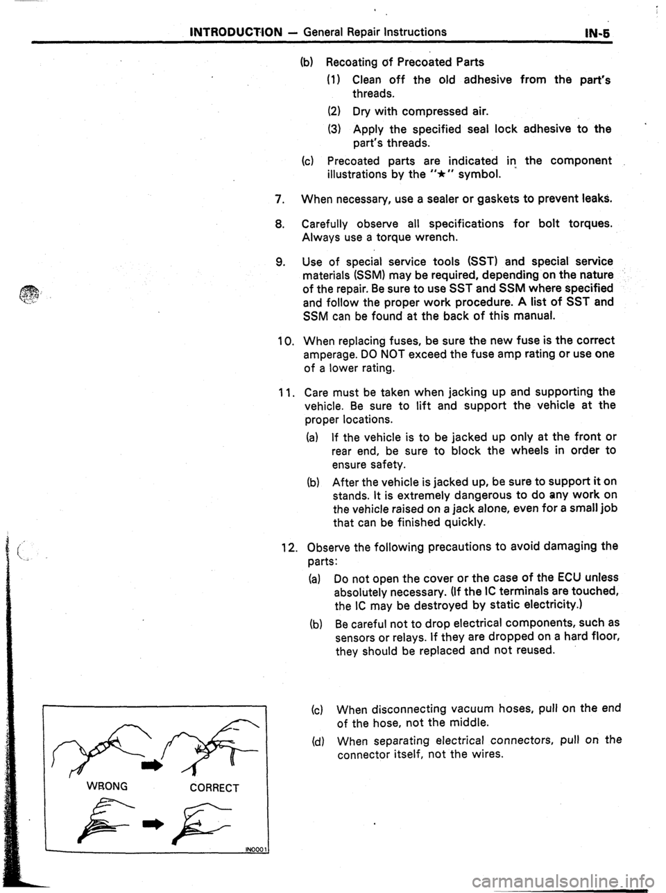
(c) When disconnecting vacuum hoses, pull on the end
of the hose, not the middle.
(d) When separating electrical connectors, pull on the
connector itself, not the wires.
Page 27 of 346
1.
2.
3.
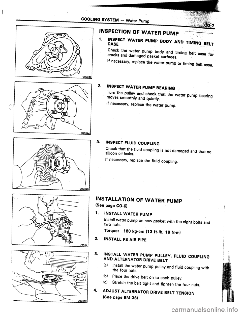
.._ INSPECT WATER PUMP BODY AND TIMI+BELT
CASE ” ._
Check the water pump body and timing b&i case for
cracks and damaged gasket surfaces.
If necessary, replace the water pump or timing belt case,
INSPECT WATER PUMP BEARINQ
Turn the pulley and check that the water pump bearing
moves smoothly and quietly.
lf necessary, replace the water pump,
INSPECT FLUID COUPLING
Check that the fluid coupling is not damaged and that no
silicon oil leaks.
If necessary, replace the fluid coupling.
INSTALLATION OF WATER PUMP
(See page CO-6)
1. INSTALL WATER PUMP
install water pump on new gasket with the eight bolts and
two nuts.
Torque:
160 kg-cm (13 ft-lb, 18 N*mI
2. INSTALL PS AIR PIPE
3. INSTALL WATER PUMP PULLEY, FLUID COUPLING
AND ALTERNATOR DRIVE BELT
(al Install the water pump pulley and fluid coupling with
the four nuts.
(b)
(c) Place the drive belt on to each pulley.
Stretch the belt tight and tighten the four nuts.
4. ADJUST ALTERNATOR DRIVE BELT TENSION
(See page EM-361
Page 31 of 346
COOLING SYSTEM - Radhtor co-11
Tank
O-Ring
Core
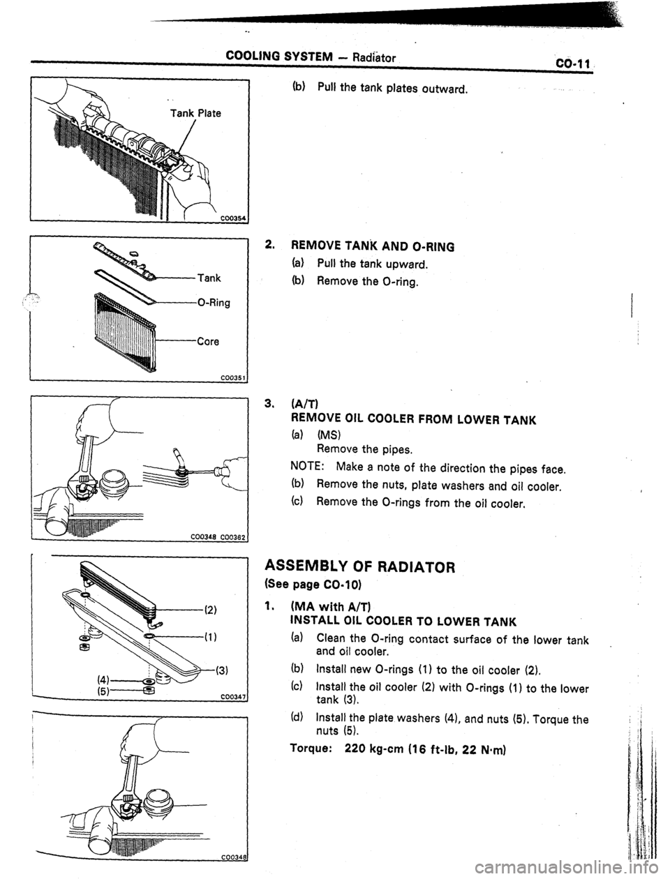
(b) Pull the tank plates outward.
2.
REMOVE TANi( AND O-RING
(a) Pull the tank upward.
(b) Remove the O-ring.
3. (A/T)
REMOVE OIL COOLER FROM LOWER TANK
(a) (MS)
Remove the pipes.
NOTE:
Make a note of the direction the pipes face.
(b) Remove the nuts, plate washers and oil cooler.
(c) Remove the O-rings from the oil cooler.
ASSEMBLY OF RADIATOR
(See page CO-lo)
1. (MA with A/T)
INSTALL OIL COOLER TO LOWER TANK
(a) Clean the O-ring contact surface of the lower tank
and oil cooler. _
(b) Install new O-rings (1) to the oil cooler (2).
(c) Install the oil cooler (2) with O-rings (1) to the lower
tank (3).
(d) Install the plate washers (4). and nuts (5). Torque the
nuts (5).
Torque: 220 kg-cm (16 f&lb, 22 Nqn)
Page 32 of 346
-.
COOLING SYSTEM - Radiator
.
ore
Plate
Core plate
XTwisteq
XTwistedl
- 2755:
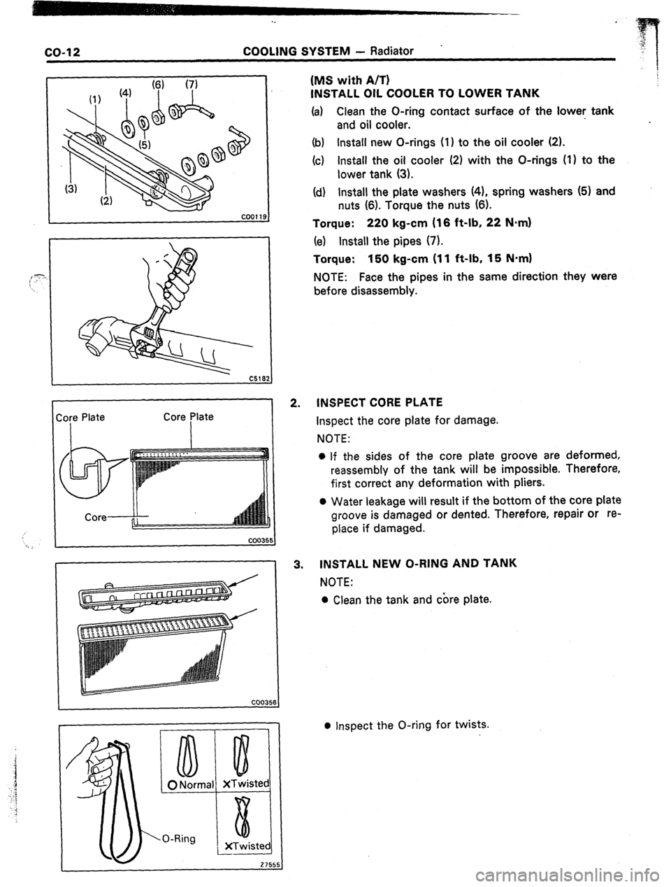
2. (MS with A/T)
INSTALL OIL COOLER TO LOWER TANK
(a)
Clean the O-ring contact surface of the
lower: tank
and oil cooler.
(b) Install new O-rings (1) to the oil cooler (2).
(c) Install the oil cooler (2) with the O-rings (1) to the
lower tank (3).
(d) Install the plate washers (41, spring washers (5) and
nuts (6). Torque the nuts (6).
Torque: 220 kg-cm (16 ft-lb, 22 N*m)
(e) Install the pipes (7).
Torque: 150 kg-cm (11 ft-lb, 15 N.mI
NOTE: Face the pipes in the same direction they were
before disassembly.
INSPECT CORE PLATE
Inspect the core plate for damage.
NOTE:
l If the sides of the core plate groove are deformed,
reassembly of the tank will be impossible. Therefore,
first correct any deformation with pliers.
0 Water leakage will result if the bottom of the core plate
groove is damaged or dented. Therefore, repair or re-
place if damaged.
3. INSTALL NEW O-RING AND TANK
NOTE:
l Clean the tank and core plate.
l Inspect the O-ring for twists.
Page 44 of 346
FI-10 EFI SYSTEM - inspection Precautions
L Fco97 FlOO91
I
. FI159
i. 4 Gasket
New
‘Gasket
I / FM067 FHOE
Fulcrum Length
19
54
-.
(b) insert the tester probe into the connector from the
wiring side when-checking the continuity,,amperage
L
or voltage.
(c) Do not apply unnecessary force to the terminal.
(d) After checking, install the water-proofing rubber on
the connector securely.
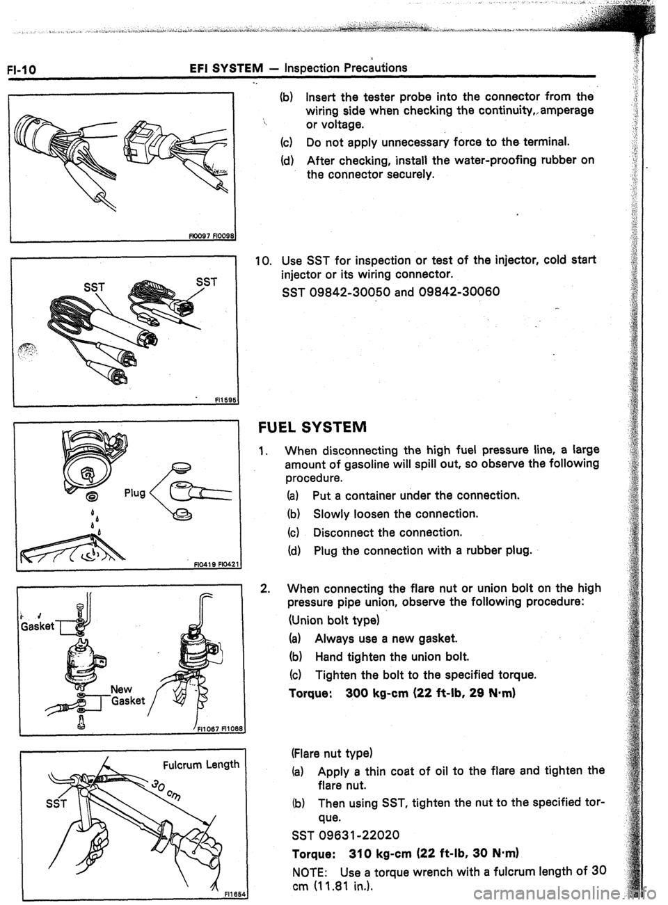
10. Use SST for inspection or test of the injector, cold start
injector or its wiring connector.
SST 09842-30050 and 09842-30060
FUEL SYSTEM
1.
2. When disconnecting the high fuel pressure line, a large
amount of gasoline will spill out, so observe the following
procedure.
(a) Put a container under the connection.
(b) Slowly loosen the connection.
(c) Disconnect the connection.
(d) Plug the connection with a rubber plug.
When connecting the flare nut or union bolt on the high
pressure pipe union, observe the following procedure:
(Union bolt type)
(a) Always use a new gasket.
(b) Hand tighten the union bolt.
(c) Tighten the bolt to the specified torque.
Torque: 300 kg-cm (22 it-lb, 29 N*m)
(Flare nut type)
(a) Apply a thin coat of oil to the flare and tighten the
flare nut.
(b) Then using SST, tighten the nut to the specified tor-
que.
SST 09631-22020
Torque: 310 kg-cm (22 ft-lb, 30 N*m)
NOTE: Use a torque wrench with a fulcrum length of 30
cm (11.81 in.).
Page 109 of 346
EFI SYSTEM - Fuel System
FI-75
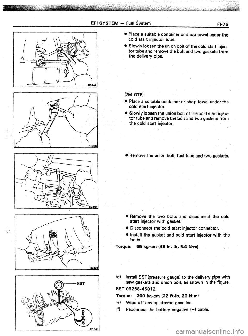
0 Place a suitable container or shop towel under the
cold start injector tube.
0 Slowly loosen the union bolt of the cold start injec-
tor tube and remove the bolt and two gaskets from
the delivery pipe.
(7M-GTE)
l Place a suitable container or shop towel under the
cold start injector.
l Slow’ly loosen the union bolt of the cold start injec-
tor tube and remove the bohand two gaskets from
the cold. start injector.
0 Remove the union bolt, fuel tube and two gaskets.
0 Remove the two bolts and disconnect the cold
start injector with gasket.
0 Disconnect the cold start injector connector.
l Install the gasket and cold start injector with the
bolts.
Torque:
55 kg-cm (48 in.-lb, 5.4 N*m),
(d) Install SST(pressure gauge) to the delivery pipe with
new gaskets and union bolt, as shown in the figure.
SST 09268-45012
Torque: 300 kg-cm (22 f&lb, 29 N-m)
(e) Wipe off any splattered gasoline.
(f) Reconnect the battery negative (-1 cable.