Page 198 of 346

EM-36 ENGINE MECHANICAL - Timinn Belt
EM302
EM301
,
A
Alternator
1
EM3000
CORRECT WRONG
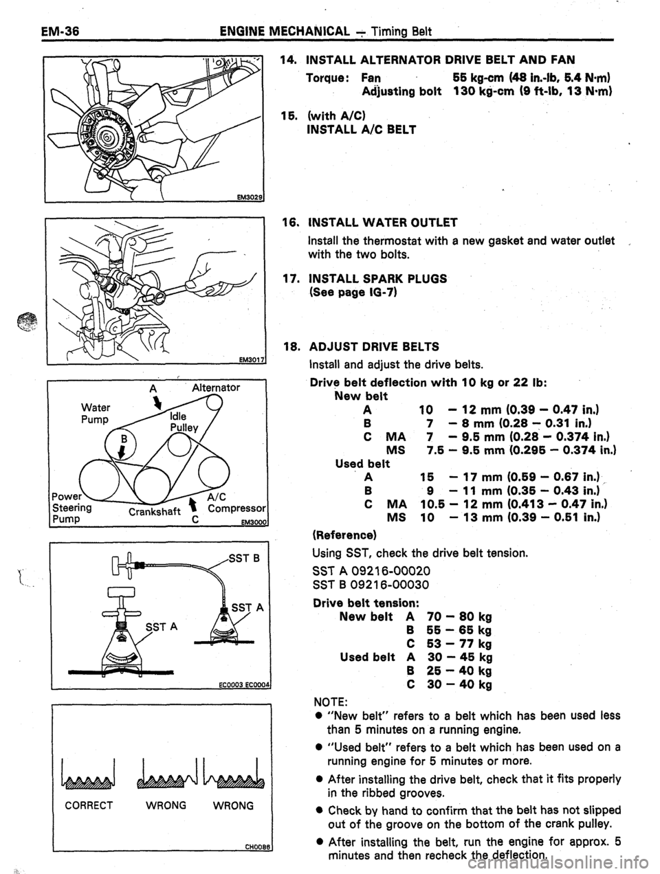
WRONG 14. INSTALL ALTERNATOR DRIVE BELT AND FAN
Torque: Fan 55 kg-cm (48 in.-lb, 6.4 N-m)
Adjusting bolt 130 kg-cm (9 ft-lb, 13 N*m)
15. (with A/C)
INSTALL A/C BELT
16. INSTALL WATER OUTLET
install the thermostat with a new gasket and water outlet
with the two bolts.
17. INSTALL SPARK PLUGS
(See page 10-7)
16. ADJUST DRIVE BELTS
Install and adjust the drive belts.
Drive belt deflection with 10 kg or 22 lb:
New belt
A 10 - 12 mm IO.39 - 0.47 in.)
B 7 - 8 mm (0.28 7 0.31 in.)
C MA 7 - 9.5 mm (0.28 - 0.374 in.)
MS 7.5 - 9.5 mm (0.296 - 0.374 in.1
Used belt
A 15 - 17 mm (0.59 - 0.67 in.1 ,
B 9 - 11 mm (0.35 - 0.43 in.)
C MA 10.5 - 12 mm (0.413 - 0.47 in.)
MS 10 - 13 mm (0.39 - 0.51 in.)
(Reference)
Using SST, check the drive belt tension.
SST A 09216-00020
SST B 09216-00030
Drive belt tension:
New belt A 70 - 80 kg
B 65 - 65 kg
C 53 - 77 kg
Used belt A 30 - 45 kg
B 25 - 40 kg
C 30 - 40 kg
NOTE:
0 “New belt” refers to a belt which has been used less
than 5 minutes on a running engine.
0 “Used belt” refers to a belt which has been used on a
running engine for 5 minutes or more.
0 After installing the drive belt, check that it fits properly
in the ribbed grooves. l Check by hand to confirm that the belt has not slipped
out of the groove on the bottom of the crank pulley.
l After installing the belt, run the engine for approx. 5
minutes and then recheck the deflection.
Page 200 of 346
EM-38
ENGINE MECHANICAL - Cylinder Head
COMPONENT? (Cont’d)
7M-GTE -.
No. 2
Cylinder Head Cover
Heater Hose Clamp
w
No. 3 Cylinder Head-
Cover
Turbocharoer
Oil Seal t
Camshaft Bearing Cap
-No. 2 Engine Hanger
Exhaust
Manifold
Stary
Water .Outlet
Housing
No.
Belt
+ Gasket
Chamber
with Connector
kg-cm (ft-lb, N-ml : Specified torque
+ Non-reusable part Intake Manifold
EM35
Page 214 of 346

EM-52
: ENGINE MECHANICAL - Cylinder Head
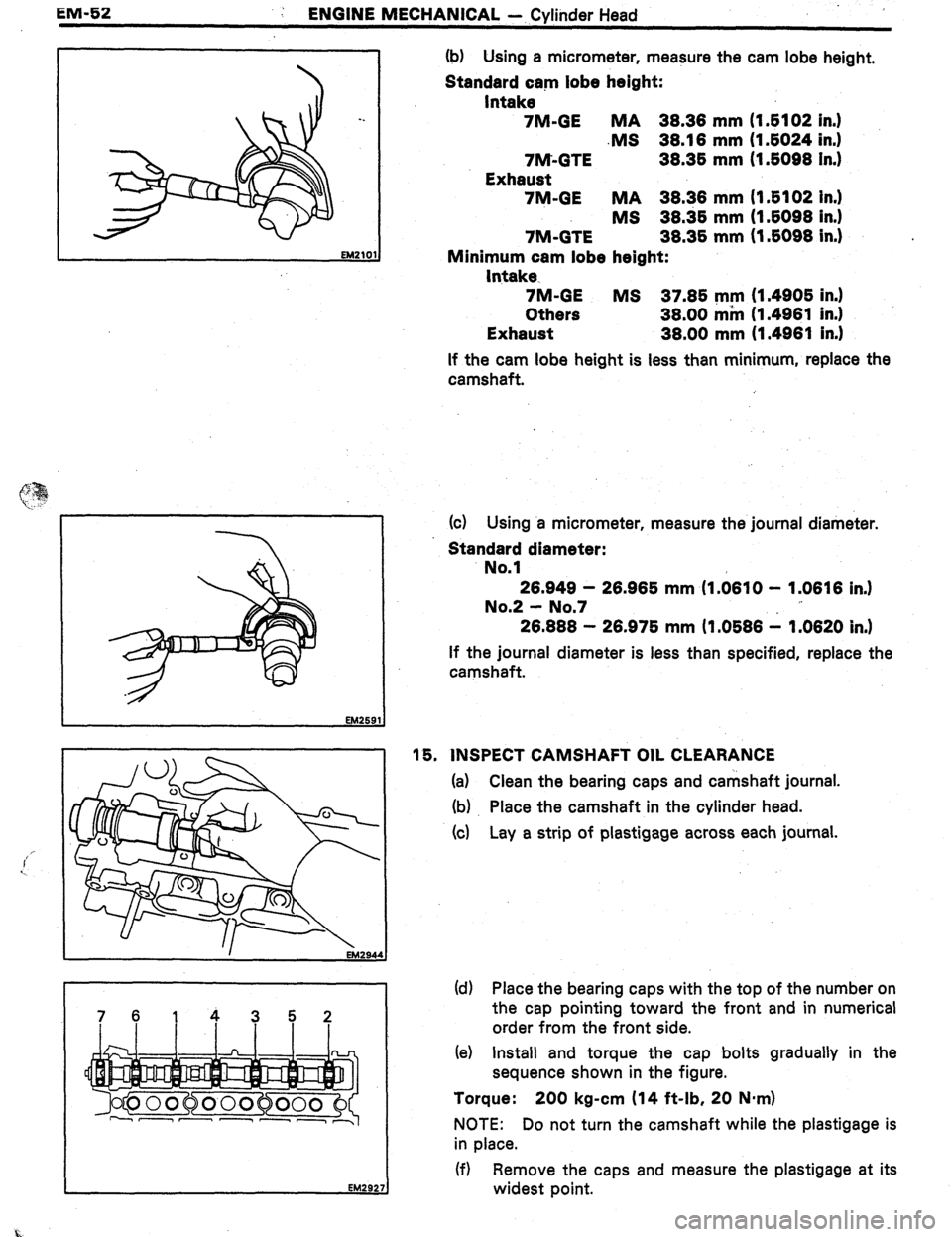
7614352 (b) Using a micrometer, measure the cam lobe height,
Standard cam lobe height:
Intake
7M-GE MA 38.38 mm (I 6102 in.1
.MS 38.18 mm (I 6024 in.1
7M-GTE 38.36 mm (1.6098 In.)
Exhaust
7M-GE MA 38.38 mm (I .6102 In.)
MS 38.36 mm (1.6098 in.1
7M-GTE 38.36 mm (1.6098 in.) .
Minimum cam lobe height:
Intake-
7M-GE MS 37.86 mm (1.4906 in.)
Others 38.00 mm (1.4981 in.)
Exhaust 38.00 mm (1.4981 in.1
If the cam lobe height is less than minimum, replace the
camshaft.
(c) Using a micrometer, measure the journal diameter.
Standard diameter:
No.1
28.949 - 28.986 mm (I .0810 - 1.0616 in.1
No.2 - No.7
26.888 - 26.976 mm (1.0686 1 1.0620 in.)
If the journal diameter is less than specified, replace the
camshaft.
16. INSPECT CAMSHAFT OIL CLEARANCE
(a) Clean the bearing caps and camshaft journal.
(b) Place the camshaft in the cylinder head.
(4 Lay a strip of plastigage across each journal.
(d) Place the bearing caps with the top of the number on
the cap pointing toward the front and in numerical
order from the front side.
(e) Install and torque the cap bolts gradually in the
sequence shown in the figure.
Torque: 200 kg-cm (14 ft-lb, 20 Nmrn)
NOTE: Do not turn the camshaft while the plastigage is
in place.
(f) Remove the caps and measure the plastigage at its
widest point.
Page 219 of 346

ENGINE MECHANICAL - Cylinder Head
EM-67
EM302
EM2921
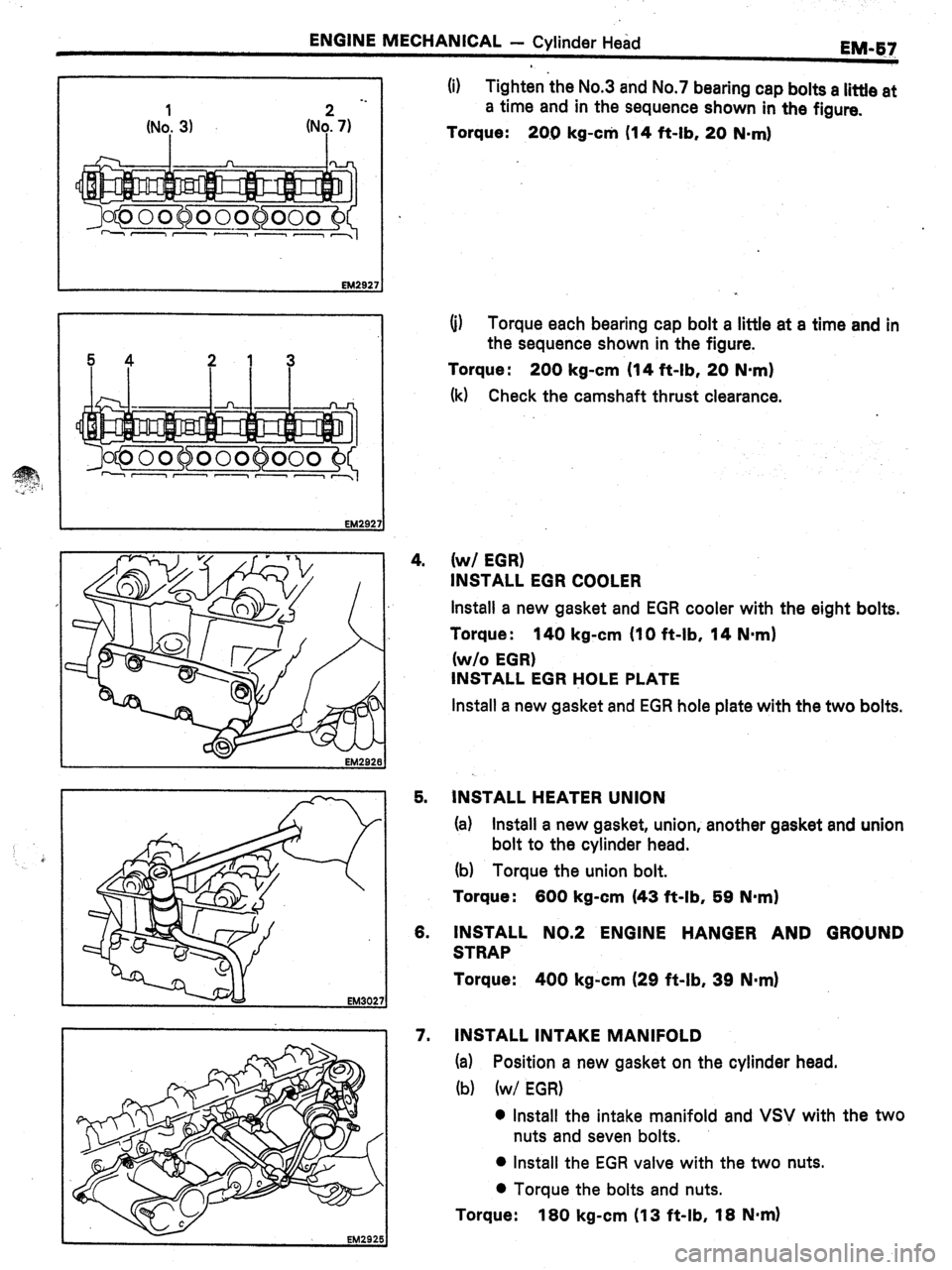
(i) Tighten the No.3 and No.7 bearing cap bolts a little at
a time and in the sequence shown in the figure.
Torque:
20.0 kg-c* (14 ft-lb, 20 N-ml
(i) Torque each bearing cap bolt a little at a time and in
the sequence shown in the figure.
Torque : 200 kg-cm (14 ft-lb, 20 N-m)
(k) Check the camshaft thrust clearance.
4.
(w/ EGR)
INSTALL EGR COOLER
Install a new gasket and EGR cooler with the eight bolts.
Torque :
140 kg-cm (IO ft-lb, 14 Nmrn)
(w/o EGR)
INSTALL EGR HOLE PLATE
Install a new gasket and EGR hole plate with the two bolts.
5. INSTALL HEATER UNION
(a) Install a new gasket, union, another gasket and union
bolt to the cylinder head.
(b) Torque the union bolt.
Torque:
600 kg-cm (43 ft-lb, 59 N-m)
6. INSTALL NO.2 ENGINE HANGER AND GROUND
STRAP
Torque:
400 kg-cm (29 ft-lb, 39 N-m)
7. INSTALL INTAKE MANIFOLD
(a) Position a new gasket on the cylinder head.
(b) (w/ EGR)
0 Install the intake manifold and VSV with the two
nuts and seven bolts.
l Install the EGR valve with the two nuts.
l Torque the bolts and nuts.
Torque: 180 kg-cm (13 ft-lb, 18 Nnrn)
Page 220 of 346
EM-58
ENGINE MECHANICAL - Cylinder Head
-.
(w/o EGR)
0 install.-the intake manifold four nuts and seven
bolts.
l Torque the bolts and nuts.
Torque :
180 kg-cm (13 ft-lb, 18 N.mI
8.
INSTALL DELIVERY PIPE WITH INJECTORS
(a)
Install the six insulators into the injector hole of the
cylinder head.
(b) Install the black rings on the upper portion of each of
the three spacers. Then install the spacers on the
delivery pipe mounting holes of the cylinder head.
(c) Place the injectors together with delivery pipe on the
cylinder head.
(d) Make sure that the injectors rotate smoothly.
(e) Install the three thinner spacers and bolts.
Torque the bolts.
Torque :
180 kg-cm (13 ft-lb, 18 N*m)
9.
INSTALL ALTERNATOR BRACKET
Torque :
400 kg-cm (29 ft-lb, 39 N.rnI
16. INSTALL NO.2 TIMING BELT COVER
Page 221 of 346

ENGINE MECHANICAL - CylinderHead
EM&Q
C Front
EX
EM300’
:
‘INSTALLATl.QN’OF CYLINDER
(See pages EM-37, 38)
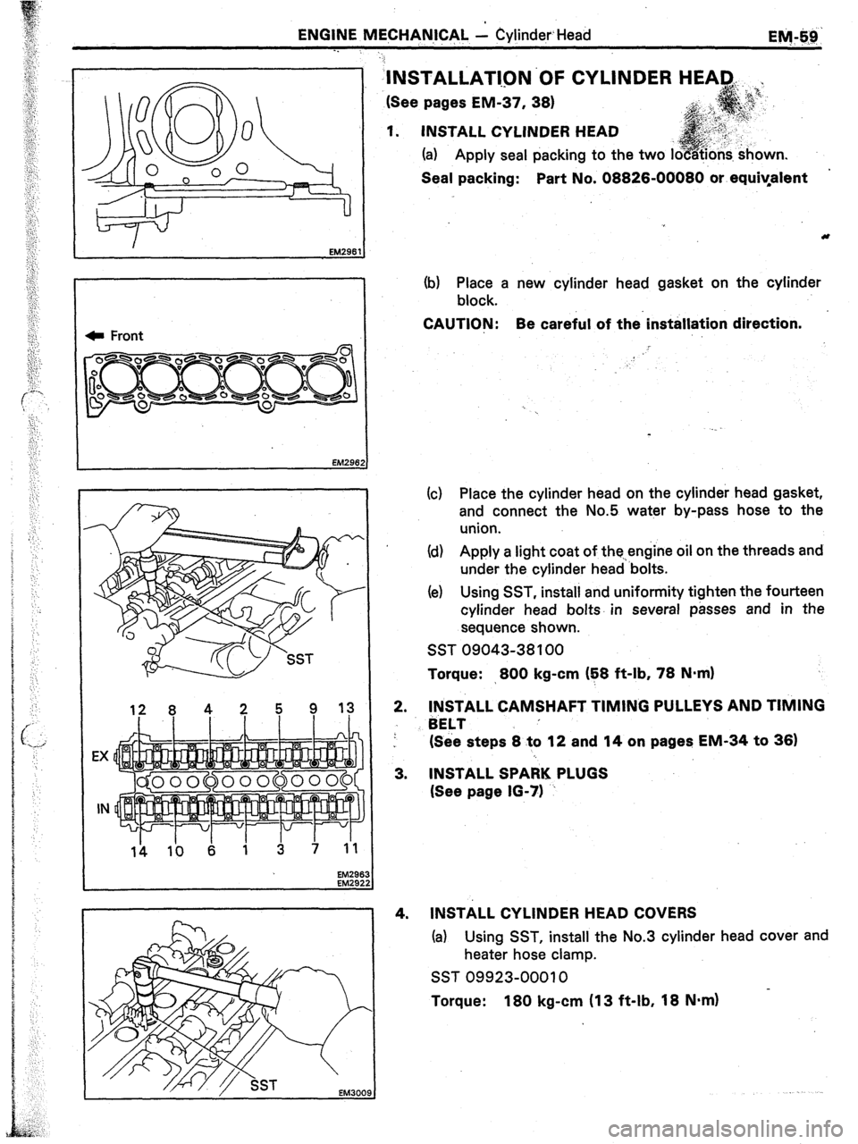
1. INSTALL CYLINDER HEAD
(a) Apply seal packing to the two i
Seal packing: Part No. 08826-00080 or equiyafent
(b) Place a new cylinder head gasket on the cylinder
block.
CAUTION: Be careful of the’installation direction.
!
(c) Place the cylinder head on the cylinder head gasket,
and connect the No.5 water by-pass hose to the
union.
Id) Apply a light coat of the.,engine oil on the threads and
under the cylinder head ‘bolts.
(e) Using SST, install and uniformity tighten the fourteen
cylinder head bolts. in several passes and in the
sequence shown.
SST 09043-38 100
Torque: >800 kg-cm (E8 ft-lb, 78 N=m)
2.
3.
4. INSTALL CAMSHAFT TIMING PULLEYS AND TIMING
BELT ’
(See steps 8 to 12 and 14 on pages EM-34 to 36)
INSTALL SPARK PLUGS
(See page 16-71 ~
INSTALL CYLINDER HEAD COVERS
(a) Using SST, install the No.3 cylinder head cover and
heater hose clamp.
SST 09923-00010 in.
Torque: 180 kg-cm (13 ft-lb, 18 N.m)
Page 222 of 346
EM-60
ENGINE MECHANICAL c Cylinder Head
(b) Apply seal packing to the cylinder head as shown in
the figure.
Seal packing: .-Part No.08826-00080 or equivalent
*
(cl Install the No.1 and No.2 cylinder head covers.
Torque: 25 kg-cm (22 in-lb, 2.5 N*m)
(d) (MA)
Install the heater hose clamp.
(e) (7M-GTE)
Install the accelerator link.
5.
INSTALL WATER OUTLET HOUSING
EM302
(a) Install a new gasket and water outlet housing with
the bolt and two nuts.
(b) Connect the No.6 water by-pass hose.
(cl, (7M-GE)
Install a new gasket, union, another gasket and union
bolt to the water outlet housing.
Front * 6. INSTALL EXHAUST MANIFOLD
(a) Face a new exhaust gasket so the protrusion is facing
the rear and install on the cylinder head.
EM2949
Page 223 of 346
ENGINE MECHANICAL- - .Cyli,nder Head
I.
(b) Install the
exhaust manifold with the seven nuts.
Torque: 400.kg-cm ‘(29 ft-lb, 39 N-m)
(c) (7M-GTE)
Install the exhaust manifold stay with the three bolts.
‘.
.(d) (TM-GTE)
install the heat insulators with the five bolts.
7. (7M-GTE)
INSTALL TURBOCHARGER
(See steps 4 to 8 and 10 to 12 on pages TC-15 to 17)
8. (7M-GE)‘
INSTALL OIL DIPSTICK
9. (7M-GE)
.
INSTALL DISTRIBUTOR AND HIGH-TENSION CORDS
(See page 10-22)