Page 111 of 346
- Fiel System
FI-77
Fl199
(p) Stop the engine. Check that the fuel pressure
remains above I.5 kg/cm2 (21 psi, 147 kPa) for 5
minutes after the engine is turned off.
If pressure is not as specified, check the fuel pump,
pressure regulator and/or injectors.
CqI After checking fuel pressure, disconnect the battery
negative (-1 cable and carefully remove the SST to
prevent gasoline from splashing.
SST 09268-45012
(r) Install cold start injector tube.
(7M-GE)
l Reconnect the cold start injector tube with new
gaskets and union bolt to the delivery pipe.
Torque: 300 kg-cm (22 ft-lb, 29 Nsm)
0 Connect the wiring connector to the cold start
injector.
(7M-GTE)
0 Remove the two bolts and cold start injector with
gasket.
0 Connect the cold start injector connector.
l Install the cold start injector tube with new four
gaskets and two union bolts.
Torque:
Delivery pipe side
300 kg-cm
(22 ft-lb, 29 N.m)
Cold start injector side 180 kg-cm
(13 ft-lb, 18 N.m)
(s) Check for fuel leakage.
Page 113 of 346

EFI SYSTEM - Fuel System
FI-79
. .
/
A Fulcrum Length
2 - 7 mm (0.08 1 0.28 in.)
Pipe Hose
k ’
em -m-d-‘,
--
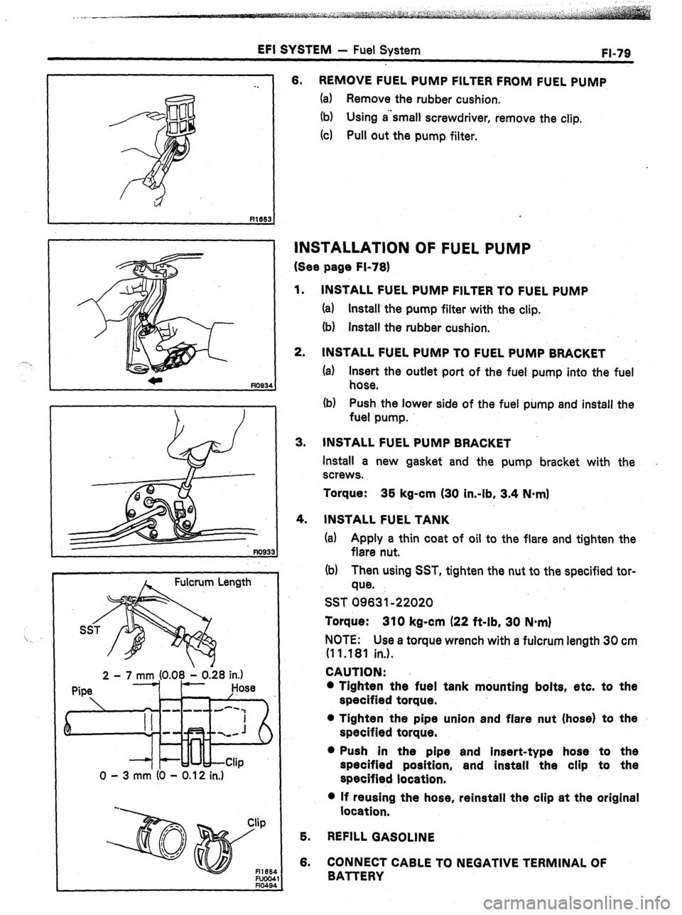
0 - 3 mm (0 - 0.12 in.) 6. REMOVE FUEL PUMP FILTER FROM FUEL PUMP
(a) Remove the rubber cushion.
(b) Using a‘small screwdriver, remove the clip.
(4 Pull out the pump filter.
INSTALLATION OF FUEL PUMP
(See page Fi-78)
1.
2. INSTALL FUEL PUMP FILTER TO FUEL PUMP
(a) Install’the pump filter with the clip.
(b) install the rubber cushion.
INSTALL FUEL PUMP TO FUEL PUMP BRACKET
(a) Insert the outlet port of the fuel pump into the fuel
hose.
(b) Push the lower side of the fuel pump and install the
fuel pump.
3. INSTALL FUEL PUMP BRACKET
Install a new gasket and the pump bracket with the
screws.
Torque: 35 kg-cm (30 in-lb, 3.4 N-m)
4.
INSTALL FUEL TANK
(a) Apply a thin coat of oil to the flare and tighten the
flare nut.
(b) Then using SST, tighten the nut to the specified tor-
que.
SST 09631~22020
Torque: 310 kg-cm (22 ft-lb, 30 N-m)
NOTE: Use a torque wrench with a fulcrum length 30 cm
(1 1 .181 in.).
CAUTION:
l Tighten the fuel tank mounting bolts, etc. to the
specified torque.
l Tighten ‘the pipe union and flare nut (hose) to the
specified torque.
l Push in the pipe and insert-type hose to the
specified position, and install the clip to the
specified location.
l If reusing the hose, reinstall the clip at the original
location,
5. REFILL GASOLINE
6. CONNECT CABLE TO NEGATIVE TERMINAL OF
BATTERY
Page 117 of 346
EFI SYSTEM - Fuel System
FI-83
. .
INSTALLATION OF COLD START INJECTOR
1.
INSTALL COLD START INJECTOR
(7M-GE)
Install a new gasket and the the cold start injector with the
,
two bolts.
Torque: 55 kg-cm (48 in.-lb, 5.4 Nqm)
2.
3.
4.
. .
5. (7M-GTE)
(a) Connect the connector to the cold start injector.
(b) Install a new gasket and the the cold start injector
with the two bolts.
,Torque: 55 kg-cm 148 in.-lb, 5.4 N-m)
INSTALL COLD START INJECTOR TUBE
Using new gaskets, connect the cold start injector tube to
the delivery pipe and cold start injector. Install the union
bolts.
Torque:
Delivery pipe side
300 kg-cm
(22 ft-lb, 29 N-m)
Cold start injector side 180 kg-cm
(13 ft-lb, 18 N-m)
17M-GE)
CONNECT COLD START INJECTOR CONNECTOR
CONNECT CABLE TO NEGATIVE TERMINAL OF
BATTERY
CHECK FOR FUEL LEAKAGE
Page 119 of 346
EFI SYSTEM - Fuel Svstem
FI-85
Pressure Regulator
Front 4
Delivery Pipe
fl1m:
FI166:
INSTALLATION OF PRESSURE REGULATOR
1. INSTALL PRESSURE REGULATOR
(a) Fully loosen the lock nut of the pressure regulator.
(b) Thrust the pressure regulator completely into, the
delivery pipe by hand.
(c) Turn the pressure regulator counterclockwise until
the outlet faces in the directi,on indicated in the
figure.
(d) Torque the lock nut.
Torque:
250 kg-cm (18 ft-lb, 25 N-m)
2.
CONNECT NO. 2 FUEL PIPE
(a) Using new gaskets, connect the No. 2 fuel pipe to the
pressure regulator. Install the union bolt.
Torque: 250 kg-cm (18 ft-lb, 25 N*mI
(b) Install the clamp bolt.
3. CONNECT VACUUM SENSING HOSE
4.
CONNECT PCV HOSE
Page 127 of 346

EFI SYSTEM - Fuel System
FI-93
-_
Pressure Requlator
Deb/Try Pipe
Front C
(e) Install the three spacers and bolts.
Torque the bolts.
Torque:
180 kg-cm (13 ft-lb, 18 N-m)
1.
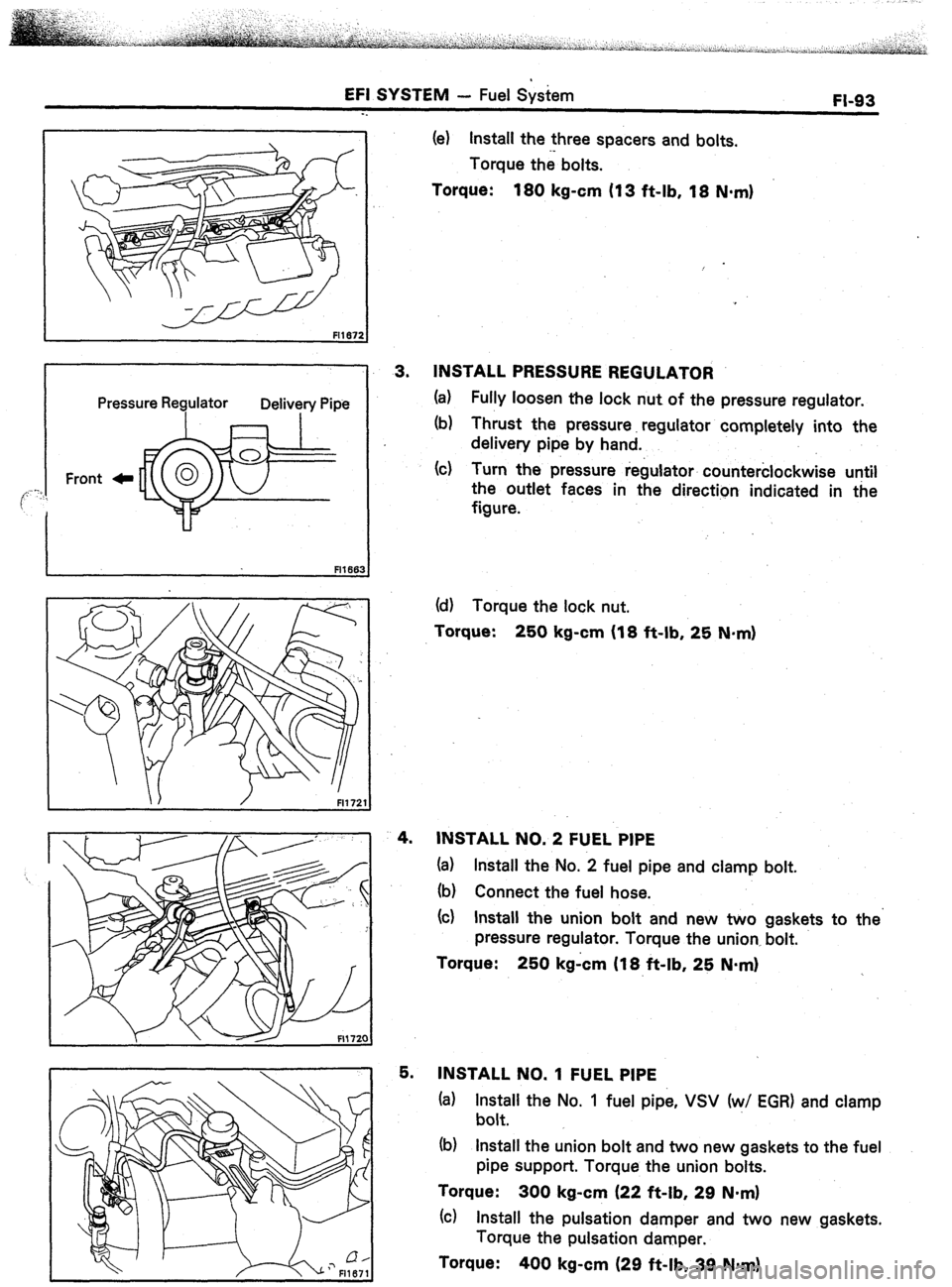
3. INSTALL PRESSURE REGULATOR
(a) Fully loosen the lock nut of the pressure regulator.
(b) Thrust the pressure. regulator completely into the
delivery pipe by hand.
(c) Turn the pressure regulator counterclockwise until
the outlet faces in the direction indicated in the
figure.
/ FI172
4.
5. (d) Torque the lock
nut.
Torque:
250 kg-cm (18 ft-lb, 25 N-m)
INSTALL NO. 2 FUEL PIPE
(a) Install the No. 2 fuel pipe and clamp bolt.
(b) Connect the fuel hose.
(cl Install the union bolt and new two gaskets to
pressure regulator. Torque the union, bolt.
Torque:
250 kgicm (18 ft-lb, 25 N*m) the’
INSTALL NO. 1 FUEL PIPE
(a) Install the No. 1 fuel pipe, VSV (w/ EGR) and clamp
bolt.
(b) Install the union bolt and two new gaskets to the fuel
pipe support. Torque the union bolts.
Torque: 300 kg-cm (22 ft-lb, 29 N.m)
(cl Install the pulsation damper and two new gaskets.
Torque the pulsation damper.
Torque:
400 kg-cm (29 ft-lb, 39 Nmrn)
Page 128 of 346
EFI SYSTEM - Fuel Svstem ’
kValve . . ..
6. CONNECT INJECTOR CONNECTORS
7. CONNECT COLD START INJECTOR TUBE TO
,.
DELIVERY PIPE
(See page FI-83)
8. INSTALL ISC VALVE
(a) Install a new gasket and ISC valve with the two bolts.
Torque: 130 kg-cm (9 ft-lb, 13 Nmrn)
(b) Connect No. 2 water by-pass hose to the ISC valve.
9. (7M-GTE)
INSTALL THROTTLE BODY
(See step 1 on page FI-106) _
10. INSTALL AIR INTAKE CONNECTOR
(7M-GE)
(a) Install a new gasket and air intake connector with the
four bolts and two nuts.
Torque: 180 kg-cm (13 ftdb, 18 Nmrn)
(b) Install- the air intake connector and throttle body
brackets.
(c) Connect th,a air cleaner hose to the throttle body.
(7M-GTE)
(See page EM-141
Page 140 of 346
FI-106 EFI SYSTEM - Air Induction S&m
-.
@ls,TAL&ATION OF THROTTLE BODY
(?M-QE)
I FIlW
I-
/
1.
2.
3.
4.
6.
6.
7.
6. INSTALL THROTTLE BODY
Install the gasket-and throttle body with the four bolts.
Torque: 130 kg-cm (9 ft-lb, 13 Narn)
CONNECT THROTTLE BODY BRACKET@
CONNECT AIR CLEANER HOSE
CONNECT THROTTLE POSITiON SENSOR
CONNECTOR
CONNECT VACUUM HOSES
CONNECT WATER HOSES
CONNECT ACCELERATOR CONNECTING ROD
REFILL WITH COOLANT
(‘/M-GTE)
1. INSTALL THROTTLE BOPY
(a) Install the two water by-pass hoses.
(b) Install a new gasket and throttle body with the four
bolts.
(c) Connect the two water by-pass hoses to the ISC
valve and water pipe.
Page 143 of 346

EFI SYSTEM - Air Induction System
FI-‘I 09
-.
!
INSPECTION OF ISC VALVE
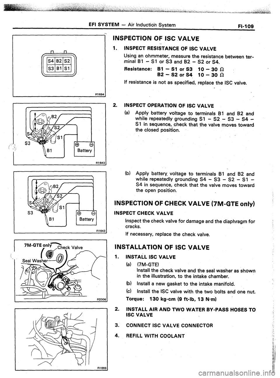
1. INSPECT RESISTANCE OF ISC VALVE
Using an ohmmeter, measure the resistance between ter-
minal B~l - Sl or S3 and 82 - S2 or S4.
Resistance: Bl -SlorS3 PO-3051
B2-S2orS4, lo-30n
If resistance is not as specified, replace the ISC valve.
2. INSPECT OPERATION OF ISC VALVE
(a) Apply battery voltage to terminals Bl and 82 and
while repeatedly grounding Sl - S2 - 53 - S4 -
S 1 in sequence,.. check that the valve moves toward
the closed position.
(b) Apply battery voltage to terminals Bl and 82 and
while repeatedly grounding S4 - S3 - S2 - Sl -
S4 in sequence, check that the valve moves toward
the open position.
INSPECTION OF CHECK VALVE (7M-GTE only)
INSPECT CHECK VALVE
Inspect the check valve for damage and the diaphragm for
cracks.
If necessary, replace the check valve.
INSTALLATION OF ISC VALVE
1. INSTAiL ISC VALVE
(a) (TM-GTE)
Install the check valve and the seal washer as shown
in the illustration, to the intake chamber.
(b) Install a new gasket to the intake manifold.
(cl Install the ISC valve with the two bolts and one nut.
Torque:
130 kg-cm (9 ft-lb, 13 N-m)
2. INSTALL All? AND TWO WATER BY-PASS HOSES TO
ISC VALVE
3. CONNECT ISC VALVE CONNECTOR
4. REFILL WITH COOLANT