Page 224 of 346

EM-62
ENGINE MECHANICAL + Cylinder Head
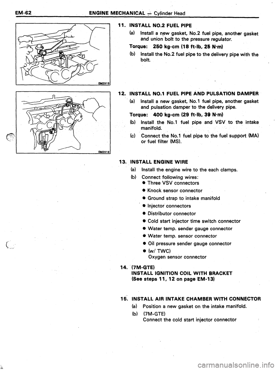
11. INSTALL NO.2 FUEL PIPE
(a) Install a r-13~ gasket, No.2 fuel pipe, another gasket
and union bolt to the pressure regulator.
Torque: 2bO kg-cm (18 ft-lb, 28 N-m)
(b) Install the No.2 fuel pipe to the delivery pipe with the
bolt.
12. INSTALL ~0.1 FUEL PIPE AND PULSATION DAMP&~
(a) Install a new gasket, No.1 fuel pipe, another gasket
and pulsation damper to the delivery pipe.
Torque: 400 kg-cm (29 ft-lb, 39 N*m)
(b) Install the No.1 fuel pipe and VSV to the intake
manifold.
(c) Connect the No.1 fuel pipe to the fuel support (MA)
or fuel filter (MS).
13. INSTALL ENGINE WIRE
(a) Install the engine wire to the each clamps.
(b) Connect following wires:
0 Three VSV connectors
0 Knock sensor connector
0 Ground strap to intake manifold
l Injector connectors
l Distributor connector
l Cold start injector time switch connector
0 Water temp. sender gauge connector
l Water temp. sensor connector
l Oil pressure sender gauge connector
l (w/ nvc)
Oxygen sensor connector
14. (7M-GTE)
INSTALL IGNITION COIL WITH BRACKET
(See steps 11, 12 on page EM-1 31
15. INSTALL AIR INTAKE CHAMBER WITH CONNECTOR
(a) Position a new gasket on the intake manifold.
(b) (7M-GTE)
Connect the cold start injector connector
Page 225 of 346
ENGINE MECHANICAL - Cylinder Head
EM-63
(c) Install the intake chamber with connector, and
vacuum transmitting pipes with the two nuts and five
bolts.
Torque: 180 kg-cm (13 f&lb, 18 N-m)
(d) Connect the engine wire to the clamps of the intake
chamber.
(e) install new gaskets and cold start injector tube.
Torque: .To delivery pipe
300 kg-cm (22 f&lb, 29. N-m)
io cold start injector
(f) (w/ EG& 180 kg-cm (I 3 ft-lb; ‘I8 N:m)
Install the EGR vacuum modulator to the bracket.
(g) (7M-GE)
Install the air intake connector bracket mounting
bolts.
(h) (7M-GE)
Install the throttle body bracket(s).
(i) (7M-GTE)
Install the ISC pipe and connect the hoses.
Page 231 of 346

ENGINE MECHANICAL L- ,Cylinder -Block . . . /
., .
. . ,. ~.,, ;-.^ j, _,. @&#J~
. .
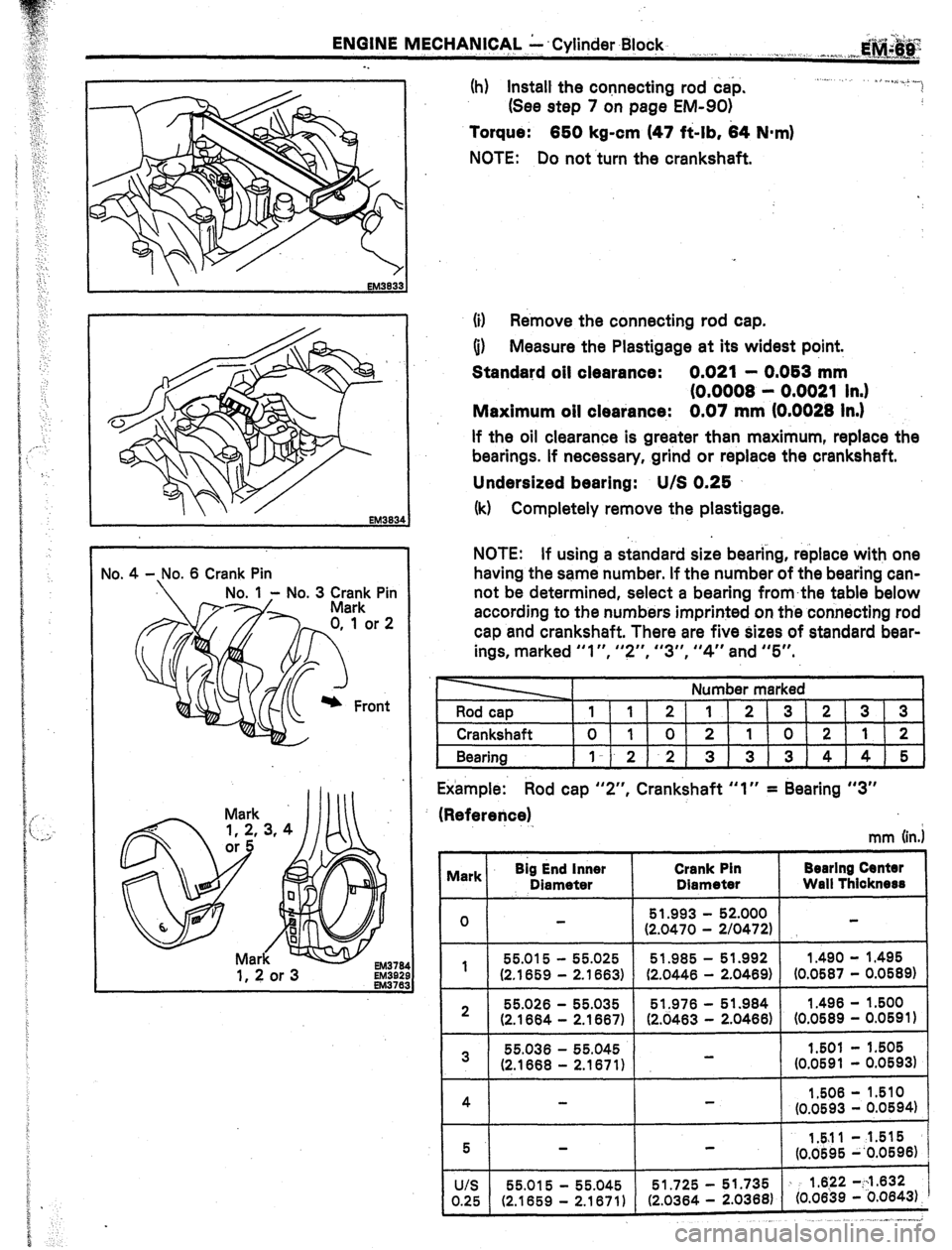
(h) Install the connecting rod cap.
(See step 7 on page EM-901
EM33
Torque: 650 kg-cm (47 f&lb, 64 N-m)
NOTE: Do not turn the crankshaft.
(iI Remove the connecting rod cap.
(i) Measure the Plastigage at its widest point.
Standard oil clearance: 0.021 - 0,063 mm
(0.0008 - 0.0021 In.)
Maximum oil clearance: 0.07 mm (0.0028 In.)
If the oil clearance is greater than maximum, replace the
bearings. If necessary, grind or replace the crankshaft.
Undersized bearing: U/S 0,25
(k) Completely remove the plastigage.
NOTE: If using a standard size bearing, replace with one
having the same number. If the number of the bearing can-
not be determined, select a bearing fromthe table below
according to the numbers imprinted on the connecting rod
cap and crankshaft. There are five sizes of standard bear-
ings, marked “I”, I’?“, “3”, “4” and “5”.
Number marked
Rod cap
lI1/2111213/21313
1 Crankshaft l0l1I01211101211121
Bearing )I-l-212) 3)313)4)415)
Example: Rod cap “Z”, Crankshaft “1” = Bearing “3”
(Refererjce)
mm (in.1
I vlark Big End inner
Diameter Crank Pin
Diameter Bearlng Centsr
Wall Thicknese
-
0 51.993 52.000 2/0472) - (2.0470 -
55.015
- 55.025 51.985
- 51.992
1.490 - 1
1.495
(2.1859 - 2.1663) (2.0446 - 2.0469) (0.0587 - 0.0589)
- 2 55.026
- 55.035 51.976
- 51.984
1.496 1.500
(2.1664 - 2.1667) (2.0463 - 2.0466)
(0.0589 - 0.0591)
55.036
- 3 55.045
I.501 - 1.505 -
(2.1668 - 2.1671) (0.0591 - 0.05931
1
I
1.506 - 1.510
(0.0593 - 0.0594)
I
,. ..__ 1” -..-.*
Page 233 of 346

ENGINE MECHANICAL Y Cylinder Block-
. . ,., ,,
..“./.. E”Q+‘J.g
. . . “h,. ,<_ .,., aa* _
. . . . . . . ..I. C/~ a....,,.?._.h, j
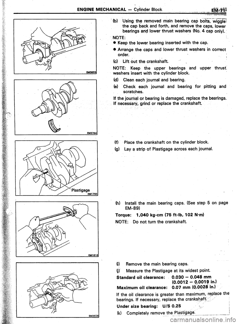
’ (b) Using the removed main bearing cap bo~t&?&gg~~
the cap back and forth,.and remove the caps, lower
bearings an! lower thrust washers (No. 4 cap only).
., NOTE: :
0 Keep the lower bearing inserted-with the cap.
0 Arrange the caps and lower thrust washers in correct
order.
9
(c) Lift out the crankshaft. “j ,
NOTE: Keep the upper bearings and upper thrust
washers insert with the cylinder block.
(d) Clean each journal and bearing.
(e) Check each journal and bearing for pitting and
scratches.
If the jounial.or bearing is damaged, replace the bearings.
If necessary, grind or replace the crankshaft,
(f)- Place the crankshaft on the cylinder block.
Cg) Lay a strip of Plastigage across each journal.
(h) Install the main bearing caps. (See step 5 on page
EM-891
Torque: 1,040 kg-&n (75 ft-lb, 102 N*m)
NOTE: Do not turn the crankshaft.
(i) Remove the main bearing caps.
(i) Measure the Plastigage at its widest point.
Standard oil clearance: . 0.030 - 0.048 mm
(0.0012 - q.0019 in.)
Maximum oil clearance: 0.07 mm ((i.0026’in.)
If the oil clearance is greater than maximum, replace the
bearings. If necessary, replace the crankshaft ,: .‘-
Under size bearing: U/S 0.25 :-.
(k) Completely remove the Plastigage. i
,^ -_ _ . j” ,,I, ,. .a”*+% -,..: :,.-__, ,-,--se. .j.z,.
Page 250 of 346
EM-88 ENGINE MECHANICAL - Cylinder Block
r
Upper Side Compression1
Front
4-- R&i
Ring No. 2 Rail EM464
No. 1 Ex. No. 1
fqJiiJ;;;;B
25 mm (0.98 in.) 22 mm (0.87 in.) EM0771
(c) Position the piston rings so that the ring ends are as
shown.
CAUTION: Do not align the ends.
3. .INSTALL BEARINGS
(a) Align the bearing claw with th,e claw groove of the
connecting.rod or connecting rod cap.
(b) Install the bearing in the con’necting rod and rod cap.
CAUTION: Install the bearings with the oil hole in the;
connecting rod.
ASFEMBLY OF CYLINDER BLOCK
(See page EM-651
NOTE:
l Thoroughly clean all parts to be assembled.
l Before installing the parts, apply new engine oil to all
sliding and rotating surfaces.
l Replace all gaskets, O-rings and oil seals with new
parts.
1. (7M-GTE)
INSTALL OIL NOZZLES
Torque: 250 kg-cm (18 ft-lb, 25 N.m)
2. INSTALL MAIN BEARINGS
NOTE: Different the bearing are used for the No. 1 and
ex. No. 1.
Page 251 of 346
ENGINE MECHANICAL A Cylinder Block
EM-@-
3.
4.
5. (a)
Align the bearing claw with the the claw -groove of.
the main bearing cap or cylind,er block.
(b)
Install the bearing in the cylinder block and bearing
caps.
GAUTION:
Install the bearing with the oil hole in the
block.
INSTALL UPPER THRUST WASHERS
Install the thrust washers under the No. 4 main journal
position of the block with the oil grooves facing outward.
PLACE &ANKSHAFT ON CYLINDER BLOCK
INSTALL MAIN BEARING CAPS AND LOWER THRUST
WASHERS
NOTE: Each bearing cap has a number and front mark.
(a) Install the thrust washers on the No. -4 bearing cap
with the grooves facing outward.
(b) Install the bearing caps in numbered order with
arrows facing forward.
(c) Install and uniformly tighten the fourteen cap bolts in
several passes, in the sequence shown.
Torque: 1,040 kg-cm (75 ft-lb, 102 N.mI
(d) Check that the crankshaft turns smoothly.
(e) Check the crankshaft thrust clearance.
(See step 21 on page EM-701
Page 252 of 346

EM-90 ENdIM IV~ECHAN~CAL - Cylinder Block
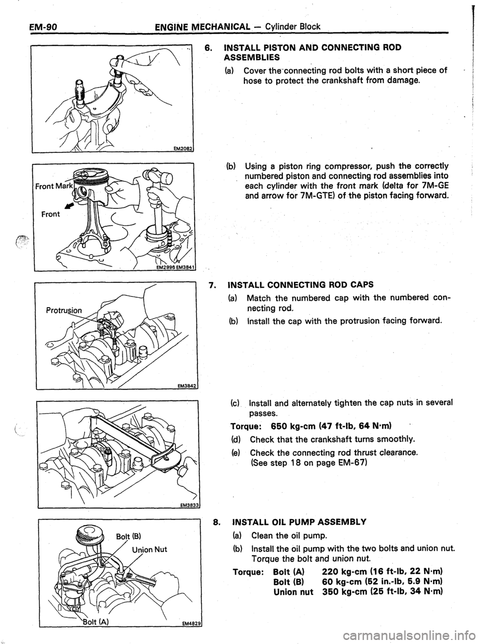
6. INSTALL PISTON AND CONNECTING ROD
ASSEMBLIES
(a) Cover the-connecting rod bolts with a short piece of
-
hose to protect the crankshaft from damage.
(b) Using a piston ring compressor, push the correctly
numbered piston and connecting rod assemblies into
each cylinder with the front mark (delta for 7M-GE
and arrow for 7M-GTE) of the piston facing forward.
EM384
EM383.
EM482
7. INSTALL CONNECTING ROD CAPS
(a) Match the numbered cap with the numbered con-
necting rod.
(b) Install the cap with the protrusion facing forward.
(c) Install and alternately tighten the cap nuts in several
passes.
Torque: 650 kg-cm (47 ft-lb, 64 N-m) .
(d) Check that the crankshaft turns smoothly.
(e) Check the connecting rod thrust clearance.
(See step 18 on page EM-671
6. JNSTALL OIL PUMP ASSEMBLY
(a) Clean the oil pump.
(b) Install the oil pump with the two bolts and union nut.
Torque the bolt and union nut.
Torque: Bolt (A) 220 kg-cm (16 ft-lb, 22 N*m)
Bolt (B) 60 kg-cm (52 in.-lb, 5.9 Nom)
Union nut 350 kg-cm (25 ft-lb, 34 Nmrn)
Page 253 of 346
ENGINE MECHANICAL - Cylinder Block
Qy g&
.
e. .-. .a ,j .a. VI ,... :~.~.**-.-. ),
9. INSTALL OIL PUMP DRIVE SHAFT
(a) While turning the drive shaft, insert slowly to avoid
damaging the drive shaft bearing.
(b) Install the bolt.
Torque:
145 kg-cm (10 ft-lb, 14 N*m)
10. INSTALL REAR OIL SEAL RETAINER
Install
a new gasket and rear oil seal retainer with the five
bolts.
Torque: 130 kg-cm (9 ft-lb, 13 N.m)
11. INSTALL TIMING BELT CASE WITH WATER PUMP
(a) Position new
gaskets on the cylinder block.
(b) Apply sealant to two or three threads of the 10 mm
bolt end.
Sealant: Part No. 08833-00070, THREE BOND 1324
or equivalent
(c) Install the timing belt case with the seven bolts and
three nuts.
12. INSTALL OIL PAN
(See page LU-14)
.13. INSTALL PS PUMP BRACKET