1987 TOYOTA CELICA length
[x] Cancel search: lengthPage 44 of 346
FI-10 EFI SYSTEM - inspection Precautions
L Fco97 FlOO91
I
. FI159
i. 4 Gasket
New
‘Gasket
I / FM067 FHOE
Fulcrum Length
19
54
-.
(b) insert the tester probe into the connector from the
wiring side when-checking the continuity,,amperage
L
or voltage.
(c) Do not apply unnecessary force to the terminal.
(d) After checking, install the water-proofing rubber on
the connector securely.
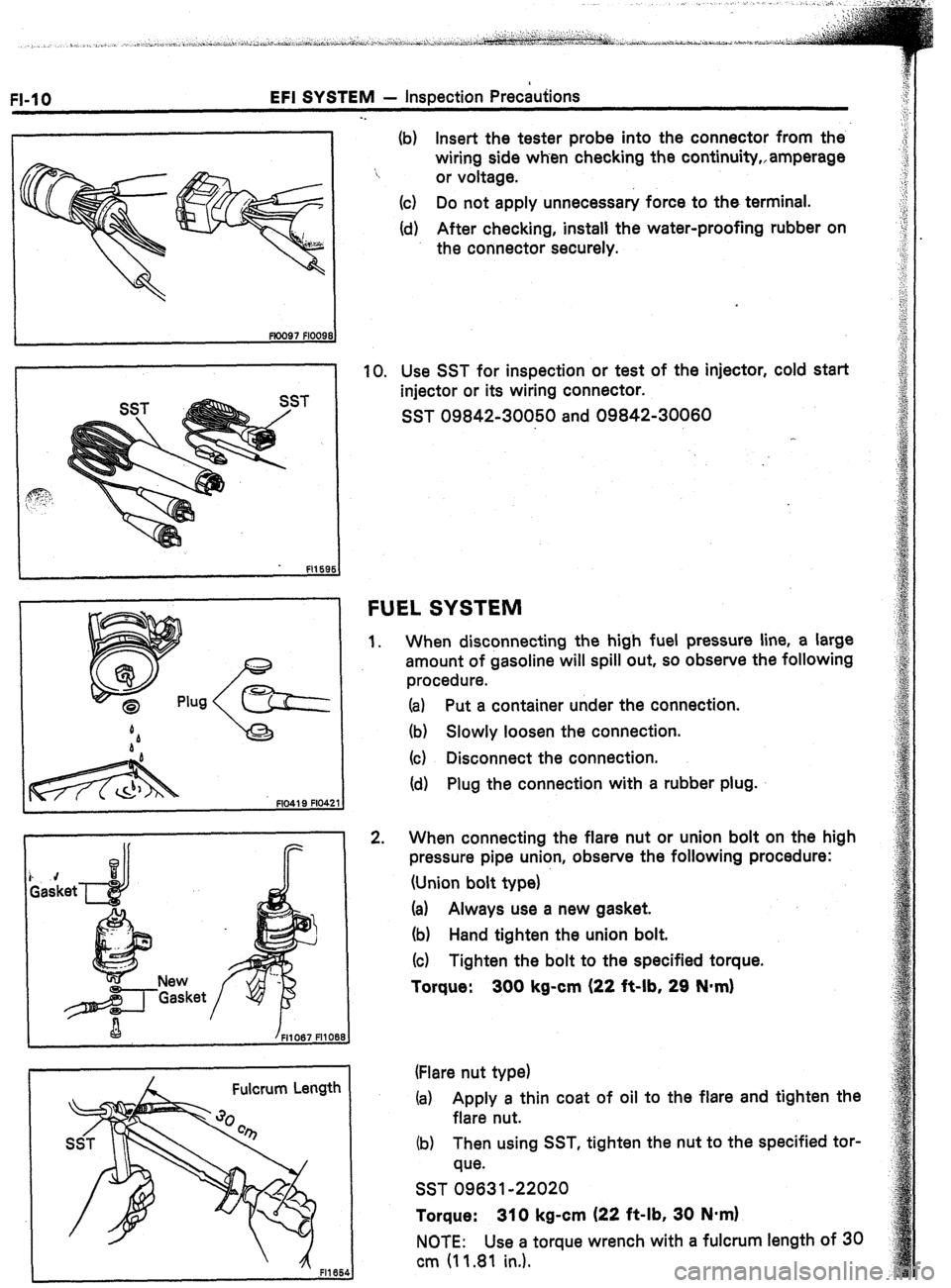
10. Use SST for inspection or test of the injector, cold start
injector or its wiring connector.
SST 09842-30050 and 09842-30060
FUEL SYSTEM
1.
2. When disconnecting the high fuel pressure line, a large
amount of gasoline will spill out, so observe the following
procedure.
(a) Put a container under the connection.
(b) Slowly loosen the connection.
(c) Disconnect the connection.
(d) Plug the connection with a rubber plug.
When connecting the flare nut or union bolt on the high
pressure pipe union, observe the following procedure:
(Union bolt type)
(a) Always use a new gasket.
(b) Hand tighten the union bolt.
(c) Tighten the bolt to the specified torque.
Torque: 300 kg-cm (22 it-lb, 29 N*m)
(Flare nut type)
(a) Apply a thin coat of oil to the flare and tighten the
flare nut.
(b) Then using SST, tighten the nut to the specified tor-
que.
SST 09631-22020
Torque: 310 kg-cm (22 ft-lb, 30 N*m)
NOTE: Use a torque wrench with a fulcrum length of 30
cm (11.81 in.).
Page 113 of 346
EFI SYSTEM - Fuel System
FI-79
. .
/
A Fulcrum Length
2 - 7 mm (0.08 1 0.28 in.)
Pipe Hose
k ’
em -m-d-‘,
--
0 - 3 mm (0 - 0.12 in.) 6. REMOVE FUEL PUMP FILTER FROM FUEL PUMP
(a) Remove the rubber cushion.
(b) Using a‘small screwdriver, remove the clip.
(4 Pull out the pump filter.
INSTALLATION OF FUEL PUMP
(See page Fi-78)
1.
2. INSTALL FUEL PUMP FILTER TO FUEL PUMP
(a) Install’the pump filter with the clip.
(b) install the rubber cushion.
INSTALL FUEL PUMP TO FUEL PUMP BRACKET
(a) Insert the outlet port of the fuel pump into the fuel
hose.
(b) Push the lower side of the fuel pump and install the
fuel pump.
3. INSTALL FUEL PUMP BRACKET
Install a new gasket and the pump bracket with the
screws.
Torque: 35 kg-cm (30 in-lb, 3.4 N-m)
4.
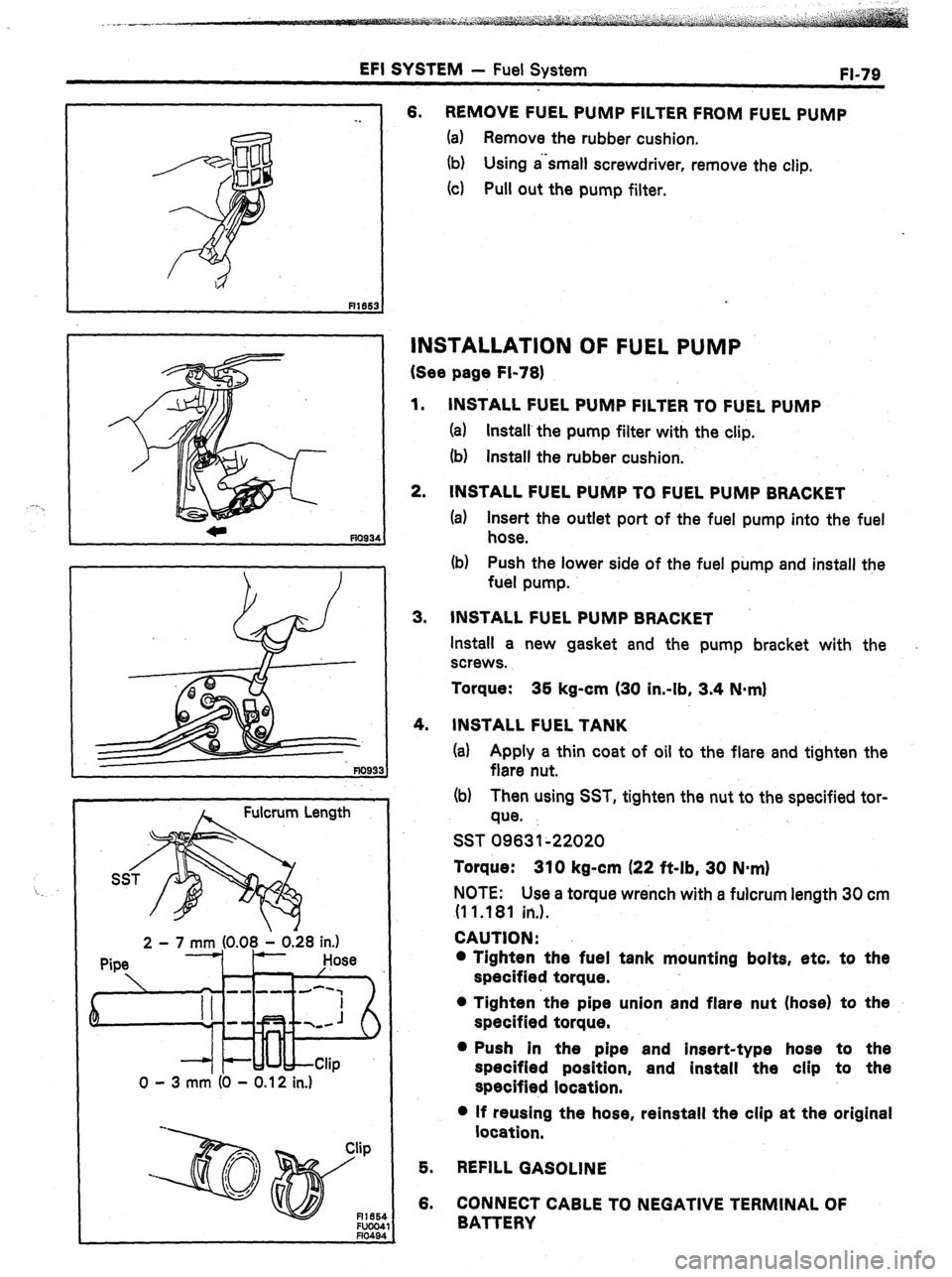
INSTALL FUEL TANK
(a) Apply a thin coat of oil to the flare and tighten the
flare nut.
(b) Then using SST, tighten the nut to the specified tor-
que.
SST 09631~22020
Torque: 310 kg-cm (22 ft-lb, 30 N-m)
NOTE: Use a torque wrench with a fulcrum length 30 cm
(1 1 .181 in.).
CAUTION:
l Tighten the fuel tank mounting bolts, etc. to the
specified torque.
l Tighten ‘the pipe union and flare nut (hose) to the
specified torque.
l Push in the pipe and insert-type hose to the
specified position, and install the clip to the
specified location.
l If reusing the hose, reinstall the clip at the original
location,
5. REFILL GASOLINE
6. CONNECT CABLE TO NEGATIVE TERMINAL OF
BATTERY
Page 165 of 346
ENGINE MECHANICAL -, Description
EM-3
The 7M-GE, 7M-GTE engines are an in-line 6-
cylinder engine with the cylinders numbered l-2-
3-4-5-6 from the front. The crankshaft is sup-
ported by 7 bearings specified by the inside of the
crankcase. These bearings are made of kelmet.
.The crankshaft is integrated with 8 weights
which are cast along with it for balancing. Oil holes
‘are built into the crankshaft for supplying oil to the
connecting rods, pistons and other components.
These engine’s ignition order is l-5-3-6-2-4 .
The cylinder head is made of aluminum alloy, with
a cross flow type intake and exhaust layout and
with pent roof type combustion chambers. The
spark plugs are located in the center of the com-
bustion chambers.
Exhaust and intake valves are equipped with
irregular pitch springs with symmetrical ends
made of oil tempered silicon chrome steel wire
which are capable of following the valves even at
,high engine speeds.
Both the exhaust side cam shaft and the. intake
side cam shaft are driven by a single timing belt.
The cam journal is supported at 7 places between
the valve lifters of each cylinder and on the
cylinder head of front end. Lubrication of the cam
journal and cam is accomplished by oil being sup-
plied through the oiler port in the center of the
camshaft.
Adjustment of the valve clearance is done by
means of an outer shim type system, in which
valve adjusting shims are located above the valve
lifters. This permits replacement of the shims
without removal of the camshafts.
The resin timing belt cover is made in 2 pieces.
Pistons are made of highly temperature-resis-
tant aluminum alloy, and depressions are built into
the piston head to prevent interference with
valves.
Piston pins are the full-floating type, with the
pins fastened to neither the piston boss nor the
connecting rods. Instead, snap rings are fitted on
both ends of the pins, preventing the pins from
falling out.
The No. 1 compression ring is made of stainless
steel and the No. 2 compression ring is made of
cast iron. The oil ring is made of a combination of
stainless steel. The outer diameter of each piston
ring is slightly larger than the diameter of the
piston
and the flexibility of the rings allows them
to hug the cylinder walls when they are mounted
on the piston. Compression rings No. 1 and No. 2
work to prevent the leakage of gas from the
cylinder and the oil ring works to scrape oil off the
cylinder walls to prevent it from entering the com-
bustion chamber.
The cylinder block is made of cast iron. It has 6
cylinders which are approximately 1.6 times the
length of the piston stroke. The top of the cylin- ders is closed off by the cylinder head and the
lower end of the cylinders becomes the crankcase,
in which the crankshaft is installed. In addition,- the
cylinder block contains a water jacket, through
which coolant is pumped to cool the cylinders.
The .oil pan is bolted onto the botiom of the
cylinder block. The oil pan is an oil reservoir made .
of pressed steel sheet. A dividing plate’is included
-inside the oil pan to keep sufficient oil in the bot-
tom of the pan even when the vehicle is tilted. This
dividing plate also prevent5 the oil from making
waves when the vehicle is stopped suddenly and
thus shifting the oil away from the oil pump suc-
tion pipe.
Page 194 of 346
EM-32
ENGINE MECHANICAL - Timing Belt
c
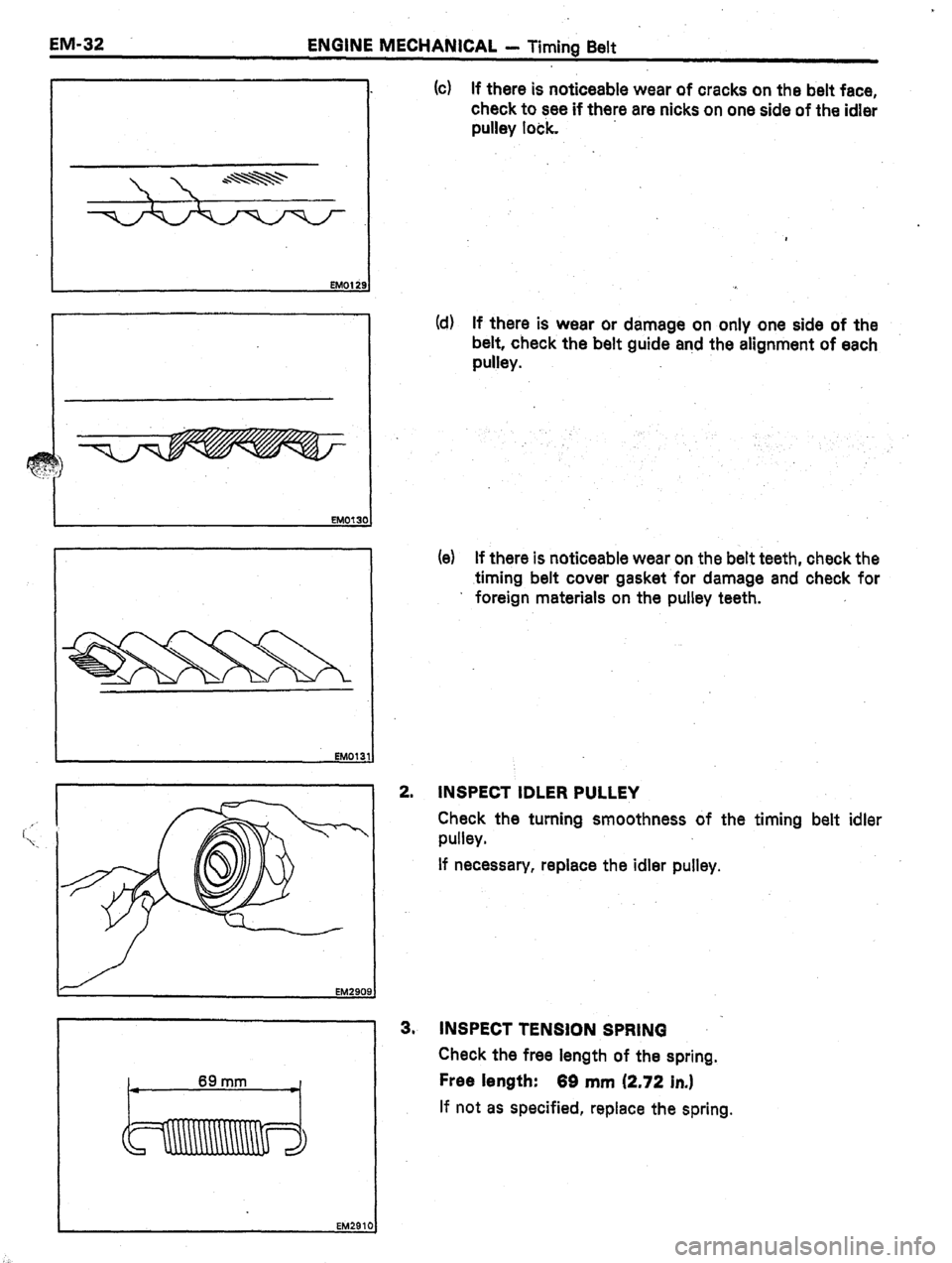
(c) If there is noticeable wear of cracks on the belt face,
check to see if there are nicks on one side of the idler
pulley lock.
Id) If there is wear or damage on only one side of the
belt, check the
belt guide and the alignment of each
pulley.
(e) If there is noticeable wear on the belt teeth, check the
.timing
belt cover gasket for damage and check for
’ foreign materials on the pulley teeth.
2,
INSPECT IDLER PULLEY
Check the turning smoothness of the timing belt idler
pulley.
If necessary, repiace the idler pulley.
EM2909.
3” INSPECT TENSION SPRING
Check the free length of the spring.
Free length:
66 mm (2.72 in.)
If not as specified, replace the spring.
Page 211 of 346
ENGINE MECHANICAL - Cylinder Head
SST
Snap Ring
EM063
82
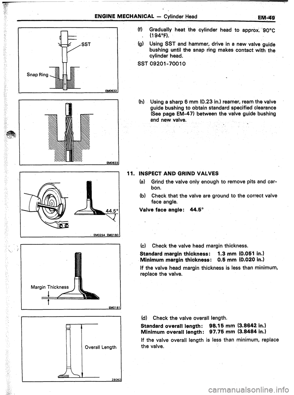
(f) $u;ily heat the cylinder head to approti; “90°C
0
*
(g) Using SST and hammer, drive in a new valve guide
bushing until the snap ring makes contact with the
cylinder head.
SST 09201-70010
Overall Length
II
[r
_-
2606.
-- ,
:,”
(h) Using a sharp 6 mm (0.23 in.) reamer, ream the valve
guide bushing to obtain standard specified clearance
(See page EM-471 between the.valve guide bushing
and new .valve.
11. INSPECT AND GRIND VALVES
(a) Grind the valve only enough to remove pits and car-
bon.
(b) Check that the valve are ground to the correct valve
face angle.
Valve face angle: 44.5”
(c) Check the valve head margin thickness.
Standard margin thickness: 1.3 mm (0.051 in.)
Minimum margin thickness: 0.5 mm (0.020 in.)
If the valve head margin thickness is less than minimum,
replace the valve.
(d) Check the valve overall length.
Standard overall length: 98.15 mm (3.8842 in.)
Minimum overall length: 97.75 mm (3.8484 in.1
If the valve overall length is less than minimum, replace
the valve.
Page 212 of 346
3
EM-50 ENGINE MECHANICAL - Cylinder Head
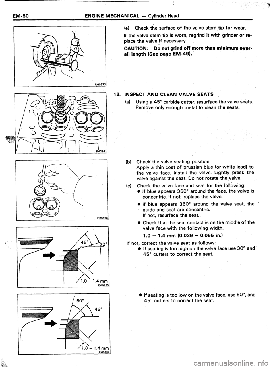
1 (e) Check the’surface of the valve stem tip for wear.
If the valve stem tip is worn, regrind it with grinder or re-
place the valve if necessary.
CAUTION: D6 not grind off more than minimum over-
all length (See page EM-49).
12.
INSPECT AND CLEAN VALVE SEATS
(a) Using a 45” carbide cutter, resurface the valve seats.
Remove only enough metal to clean the seats.
EM3026
(b) Check the valve seating position.
Apply a thin coat of prussian blue (or white lead) to
the valve face. Install the valve. Lightly press the
valve against the seat. Do not rotate the valve.
(c) Check the valve face and seat for the following:
0 If blue appears 360” around the face, the valve is
concentric. If not, replace the valve.
0 If blue appears 360” around the valve seat, the
guide and seat are concentric.
If not, resurface the seat.
0 Check that the seat contact is on the middle of the
valve face with the following width.
1.0 - 1.4 mm (0.039 - 0.055 in.1
If not, correct the valve seat as follows:
0 If seating is too high on the valve face use 30” and
45” cutters to correct the seat.
l If seating is too low on the valve face, use 60°. and
45” cutters to correct the seat.
Page 213 of 346
ENGINE MECHANICAL -, Cylinder Head
EM-5J
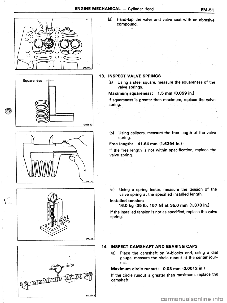
Squareness -+- (d) Hand-lap the valve and valve seat with an abrasive
compound.
. .
13. INSPECT VALVE SPRINGS
(a) Using a steel square, measure the squareness of the
valve springs.
Maximum. squareness: 1.5 mm (0.059 in.)
If squareness .is greater than maximum, replace the valve
spring.
(b) Using calipers, measure the free length of the valve
spring.
Free length : 41.64 mm (1.6394 in.)
If the free length is not within specification, replace the
valve spring.
(c) Using a spring tester, measure the tension of the
valve spring at the specified installed length.
Installed tension :
16.0 kg (35 lb, 157 N) at 35.0 mm (1.378 in.)
If the installed tension is not as specified, replace the valve
spring.
14. INSPECT CAMSHAFT AND BEARING CAPS
(a) Place the camshaft on V-blocks and, using a dial
gauge, measure the circle runout at the center jour-
nal.
Maximum circle runout: 0.03 mm (0.0012 in.)
If the circle runout is greater than maximum, replace the
camshaft.
Page 322 of 346
_. I STARTING SYSTEM T Starter
ST-
-’ “’ .I
ST004
/
No continuity
ST0201 0
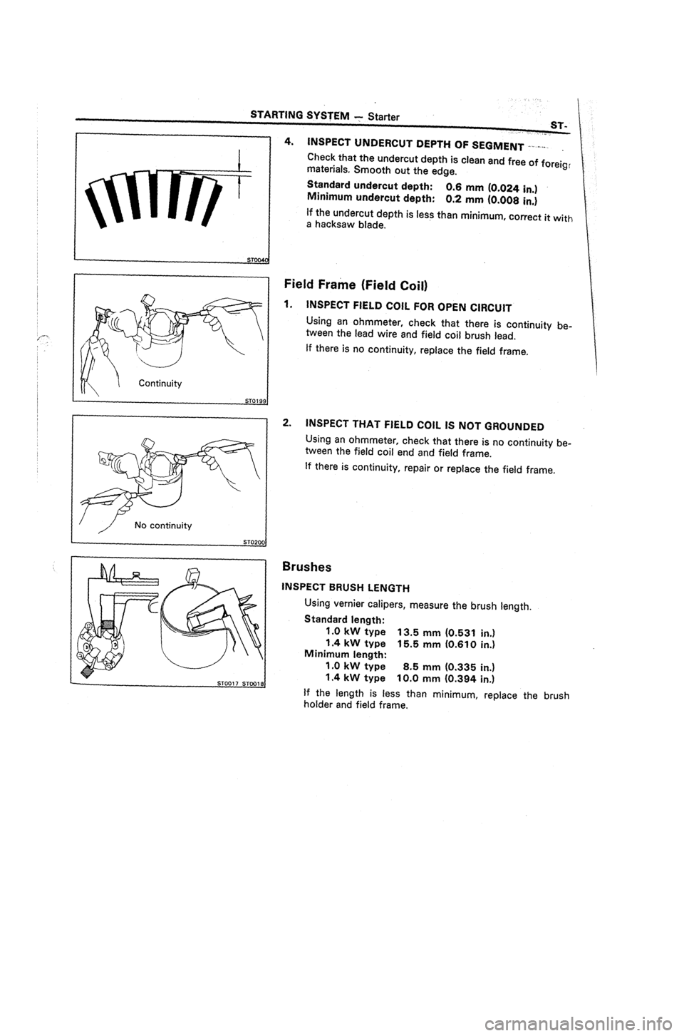
4. INSPECT UNDERCUT DEPTH OF SEGMENT I-.-.v-.
.
Check that the undercut depth is clean and free of foreig,
materials. Smooth out the edge.
Standard undercut depth:
Minimum undercut depth: 0.6 mm (0.024 in.)
0.2 mm (0.008 in.)
If the undercut depth is less than minimum, correct it
with
a
hacksaw blade.
Field Frame (Field Coil)
1.
INSPECT FIELD COIL FOR OPEN CIRCUIT
Using an ohmmeter, check that there is continuity be-
tween the lead wire and field coil brush lead.
If there is no continuity, replace the field frame.
2.
INSPECT THAT FIELD COIL IS NOT GROUNDED
Using an ohmmeter, check that there is no continuity be-
tween the field coil end and field frame.
If there is continuity, repair or replace the field frame.
Brushes
INSPECT BRUSH LENGTH
Using vernier calipers, measure the brush length.
Standard length:
1 .O kW type 13.5 mm (0.531 in.)
1.4 kW type 15.5 mm (0.610 in.)
Minimum length:
1.0 kW type 8.5 mm (0.335 in.)
1.4 kW type 10.0 mm (0.394 in.)
If the length is less than minimum, replace the brush
holder and field frame.