Page 109 of 346
EFI SYSTEM - Fuel System
FI-75
0 Place a suitable container or shop towel under the
cold start injector tube.
0 Slowly loosen the union bolt of the cold start injec-
tor tube and remove the bolt and two gaskets from
the delivery pipe.
(7M-GTE)
l Place a suitable container or shop towel under the
cold start injector.
l Slow’ly loosen the union bolt of the cold start injec-
tor tube and remove the bohand two gaskets from
the cold. start injector.
0 Remove the union bolt, fuel tube and two gaskets.
0 Remove the two bolts and disconnect the cold
start injector with gasket.
0 Disconnect the cold start injector connector.
l Install the gasket and cold start injector with the
bolts.
Torque:
55 kg-cm (48 in.-lb, 5.4 N*m),
(d) Install SST(pressure gauge) to the delivery pipe with
new gaskets and union bolt, as shown in the figure.
SST 09268-45012
Torque: 300 kg-cm (22 f&lb, 29 N-m)
(e) Wipe off any splattered gasoline.
(f) Reconnect the battery negative (-1 cable.
Page 114 of 346
EFI SYSTEM - Fuel System
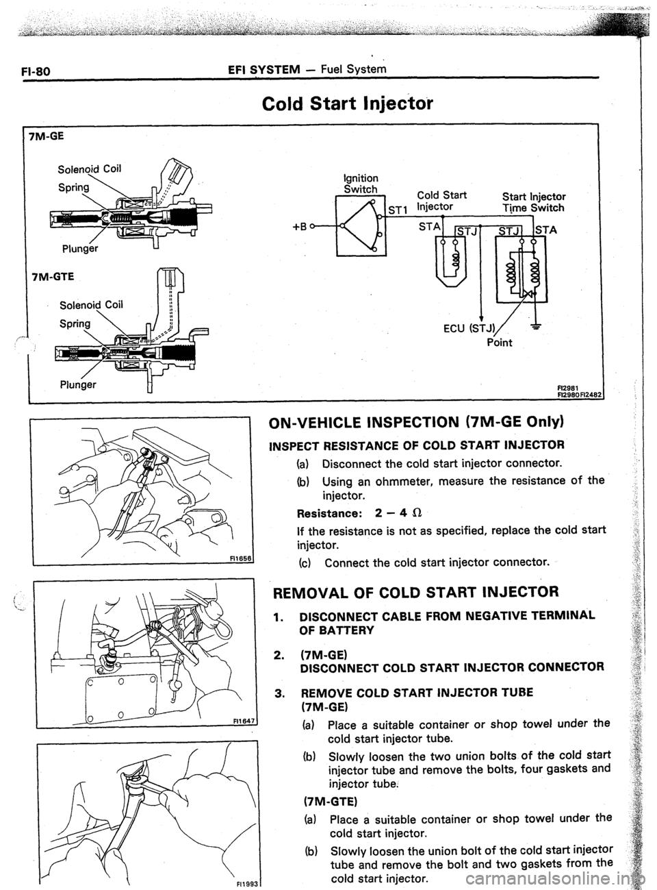
Cold Start Injector
I Plunger H
+B
*--!1?-- lgnlrlon
Switch Cold Start
sisrt InioFtnr I --.- -.. injector V.“. . .I .,Y”....
Time Switch
1 7
ON-VEHICLE INSPECTION (7M-GE Only)
INSPECT RESISTANCE OF COLD START INJECTOR
(a) Disconnect the cold start injector connector.
(b) Using an ohmmeter, measure the resistance of the
injector.
Resistance: 2 - 4 fi
If the resistance is not as specified, replace the cold start
injector.
(c) Connect the cold start injector connector.
REMOVAL OF COLD START INJECTOR
1.
2.
3. DISCONNECT CABLE FROM NEGATIVE TERMINAL
OF BATTERY
(7M-GE)
DISCONNECT COLD START INJECTOR CONNECTOR
REMOVE COLD START INJECTOR TUBE
(‘IM-GE)
(a) Place a suitable container or shop towel under the
cold start injector tube.
(b) Slowly loosen the two union bolts of the cold start
injector tube and remove the bolts, four gaskets and
injector tube.
(7M-GTE)
(a) Place a suitable container or shop towel under the
cold start injector.
(b) Slowly loosen the union bolt of the cold start injector
tube and remove the bolt and two gaskets from the
cold start injector.
Page 118 of 346
l-84 EFI SYSTEM - Fuel System’
-.
Pressure Regulator
._
Spring-
Valve- Pressure Regulator
I
-Diaphragm
TO RETURN
PIPE
FROM DELIVERY
PIPE
No. 2. Fuel Pipe
I31659 Fl168'
ON-VEHICLE INSPECTION
INSPECT FUEL PRESSURE (See page FI-74)
REMOVAL OF PRESSURE REGULATOR
1. DISCONNECT PCV HOSE
2. DISCONNECT VACUUM SENSING HOSE
3. DISCONNECT NO.2 FUEL PIPE
(4
Place a suitable container or shop towel under the
pressure regulator.
(b) Remove the union bolt and two gaskets.
(cl
Remove the clamp bolt of the No.2 fuel pipe.
4.
REMOVE PRESSURE REGULATOR
Loosen the lock nut, and remove the pressure regulator.
,
Page 143 of 346
EFI SYSTEM - Air Induction System
FI-‘I 09
-.
!
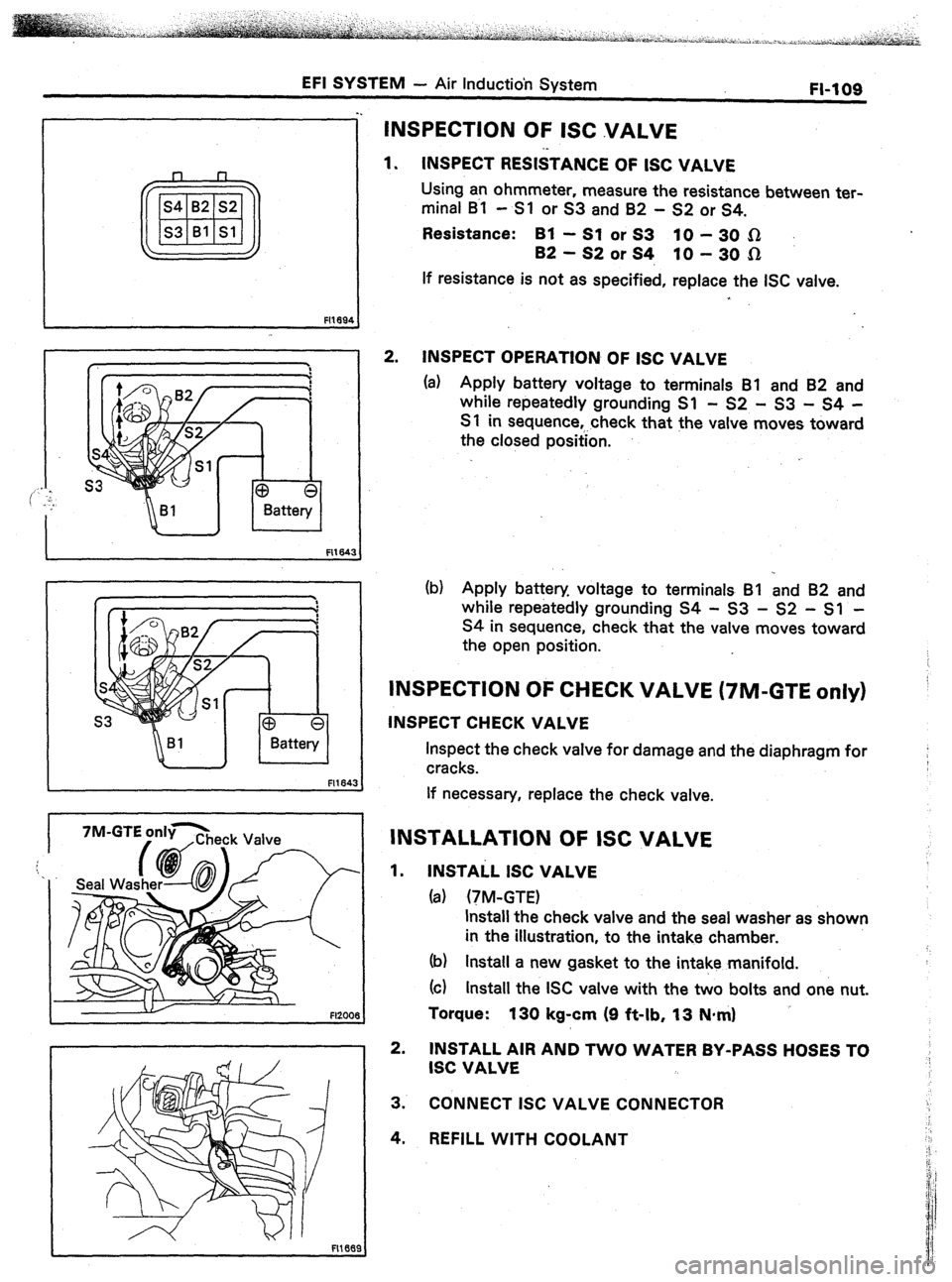
INSPECTION OF ISC VALVE
1. INSPECT RESISTANCE OF ISC VALVE
Using an ohmmeter, measure the resistance between ter-
minal B~l - Sl or S3 and 82 - S2 or S4.
Resistance: Bl -SlorS3 PO-3051
B2-S2orS4, lo-30n
If resistance is not as specified, replace the ISC valve.
2. INSPECT OPERATION OF ISC VALVE
(a) Apply battery voltage to terminals Bl and 82 and
while repeatedly grounding Sl - S2 - 53 - S4 -
S 1 in sequence,.. check that the valve moves toward
the closed position.
(b) Apply battery voltage to terminals Bl and 82 and
while repeatedly grounding S4 - S3 - S2 - Sl -
S4 in sequence, check that the valve moves toward
the open position.
INSPECTION OF CHECK VALVE (7M-GTE only)
INSPECT CHECK VALVE
Inspect the check valve for damage and the diaphragm for
cracks.
If necessary, replace the check valve.
INSTALLATION OF ISC VALVE
1. INSTAiL ISC VALVE
(a) (TM-GTE)
Install the check valve and the seal washer as shown
in the illustration, to the intake chamber.
(b) Install a new gasket to the intake manifold.
(cl Install the ISC valve with the two bolts and one nut.
Torque:
130 kg-cm (9 ft-lb, 13 N-m)
2. INSTALL All? AND TWO WATER BY-PASS HOSES TO
ISC VALVE
3. CONNECT ISC VALVE CONNECTOR
4. REFILL WITH COOLANT
Page 171 of 346
ENGINE MECHANICAL - Engine Tune-up
3.
* MEA&E VALVE CLEARANCE I
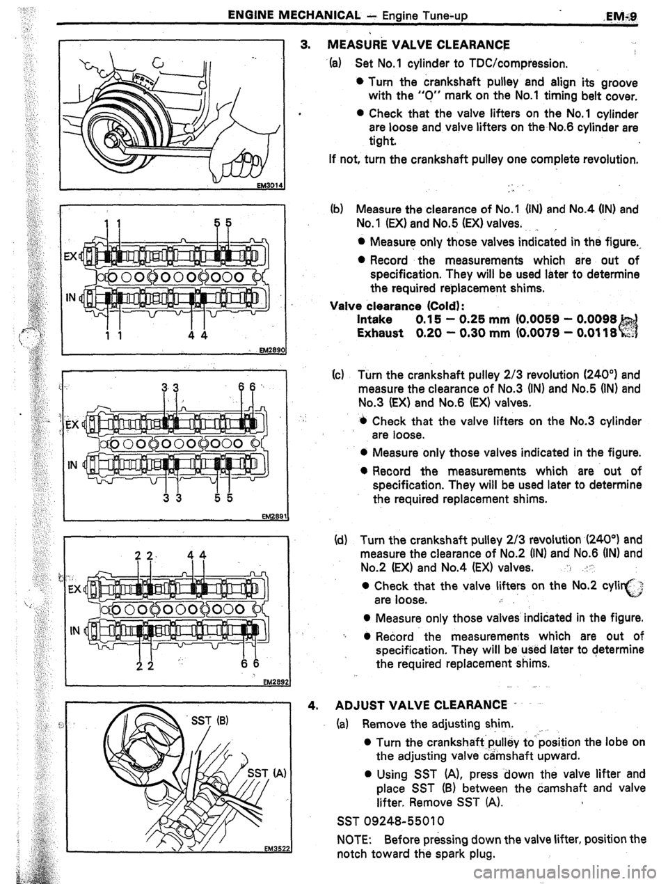
4. (a) Set No.1 cylinder to TDC/compression.
l Turn the crankshaft pulley and align its groove
with the “0” mark on the No.1 timing belt cover,
l Check that the valve lifters on the No.1 cylinder
are loose and valve lifters on the No.6 cylinder are
tight.
If not, turn the crankshaft pulley one complete revolution.
. .
. .
(b) Measure the clearance of No.1 (INI and No.4 (IN) and
No.1 (EX) and No.5 (EX) valves.
. . . .
l Measure only those valves indicated in the figure.,
0 Record the measurements which are. out of
specification. They will be used later to determine
the required reblacement shims.
Valve clearance (Cold) :
Intake 0.15 - 0.25 mm (0.0059 - 0.0098
Exhaust 0.20 - 0.30 mm (0.0079 - 0.0118
(c(c) Turn the crankshaft pulley 2/3 revolution (240”) and
measure the clearance of No.3 (IN) and No.5 (IN) and
No.3 (EX) and No.6 (EX) valves.
4 Check that the valve lifters on the No.3 cylinder
are loose.
0 Measure only those valves indicated in the figure.
l Record the measurements which are out of
specification. They will be used later to determine
the required replacement shims.
(d) Turn the crankshaft pulley 2/3 revolution ,(240°) and
measure the clearance of No.2 (IN) and No.6 (IN) and
No.2 (EX) and No.4 (EX) valves. : .-:1’.
0 Check that the valve lifters on the No.2 cyli i,:..?
are loose. c
.i
0 Measure only those valves indidated in the figure.
-I 0 Record the measurements which are out of
specification. They will be used later to determine
the required replacement shims.
ADJUST VALVE CLEARANCE .
(a) Remove the adjusting shim. ,
0 Turn the crankshaft.pulley to’ position the lobe on
the adjusting valve camshaft upward.
0 Using SST (A), press down the valve lifter and
place SST (B) between the camshaft and valve
lifter. Remove SST (A).
SST 09248-55010
NOTE: Before pressing down the valve lifter, position the
notch toward the spark plug.
Page 195 of 346
ENGINE MECHANICAL - Timing Belt
EM291
EM303’
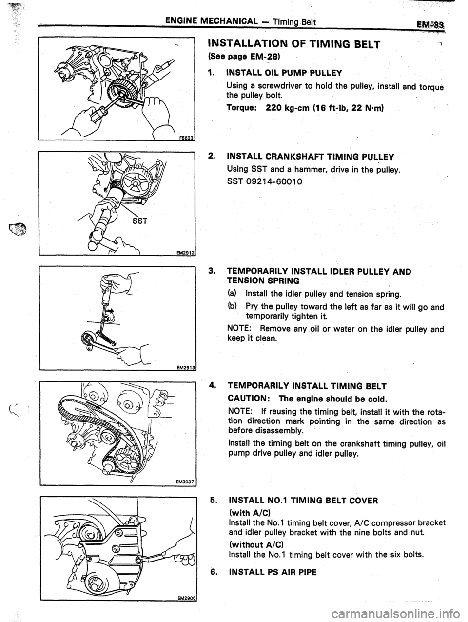
INSTALLATION OF TIMING BELT
(See page EM-281
._
1. INSTALL OIL PUMP PULLEY
“3
Using a screwdriver to hold the pulley, install and torque
the pulley bolt.
Torque: 220 kg-cm (16 ft-lb, 22 Nnrn)
2.
INSTALL CRANKSHAFT TIMING PULLEY
Using SST and a hammer, drive in the pulley.
SST 09214-60010
3. TEMPORARILY INSTALL IDLER PULLEY AND
TENSION SPRING
*’
(a) Install the idler pulley and tension spring.
(b) Pry the pulley toward the left as far as it will go and
temporarily tighten it.
NOTE: Remove any oil or water on the idler pulley and
keep it clean.
4. TEMPORARILY INSTALL TIMING BELT
CAUTION: The engine should be cold.
NOTE: If reusing the timing belt, install it with the rota-
tion direction mark pointing in the same direction as
before disassembly.
Install the timing belt on the crankshaft timing pulley, oil
pump drive pulley and idler pulley.
5. INSTALL NO.1 TIMING BELT COVER
(with A/C)
Install the No. 1 timing belt cover, A/C compressor bracket
and idler pulley bracket with the nine bolts and nut.
(without A/C)
Install the No.1 timing belt cover with the six bolts.
6. INSTALL PS AIR PIPE
Page 214 of 346
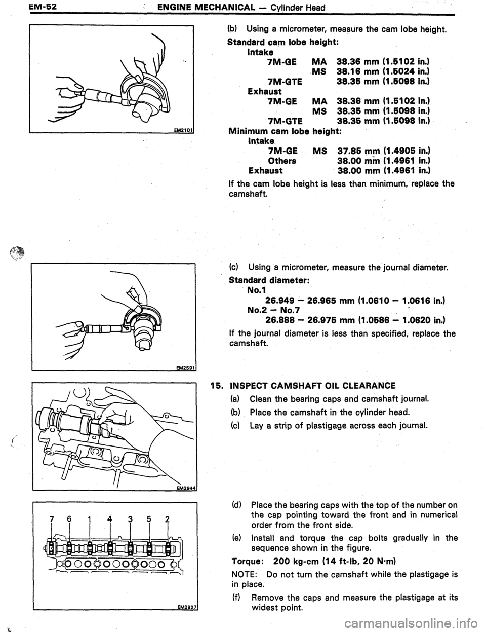
EM-52
: ENGINE MECHANICAL - Cylinder Head
7614352 (b) Using a micrometer, measure the cam lobe height,
Standard cam lobe height:
Intake
7M-GE MA 38.38 mm (I 6102 in.1
.MS 38.18 mm (I 6024 in.1
7M-GTE 38.36 mm (1.6098 In.)
Exhaust
7M-GE MA 38.38 mm (I .6102 In.)
MS 38.36 mm (1.6098 in.1
7M-GTE 38.36 mm (1.6098 in.) .
Minimum cam lobe height:
Intake-
7M-GE MS 37.86 mm (1.4906 in.)
Others 38.00 mm (1.4981 in.)
Exhaust 38.00 mm (1.4981 in.1
If the cam lobe height is less than minimum, replace the
camshaft.
(c) Using a micrometer, measure the journal diameter.
Standard diameter:
No.1
28.949 - 28.986 mm (I .0810 - 1.0616 in.1
No.2 - No.7
26.888 - 26.976 mm (1.0686 1 1.0620 in.)
If the journal diameter is less than specified, replace the
camshaft.
16. INSPECT CAMSHAFT OIL CLEARANCE
(a) Clean the bearing caps and camshaft journal.
(b) Place the camshaft in the cylinder head.
(4 Lay a strip of plastigage across each journal.
(d) Place the bearing caps with the top of the number on
the cap pointing toward the front and in numerical
order from the front side.
(e) Install and torque the cap bolts gradually in the
sequence shown in the figure.
Torque: 200 kg-cm (14 ft-lb, 20 Nmrn)
NOTE: Do not turn the camshaft while the plastigage is
in place.
(f) Remove the caps and measure the plastigage at its
widest point.
Page 218 of 346
EM-56
ENGINE MECHANICAL - Cylinder f-lead
I-
I: Intake
E: ljxhaust No.? - No. 7
Front Mark Intake
Exhaust (4 Coat all bearing journals with engine oil.
(d) Place the camshafts on the cylinder head as shown in
the figure,
NOTE: The eihaust camshaft has a distributor (‘IM-GE)
or cam position sensor (7M-GTE) drive gear.
(e) Apply seal packing to the areas indicated in the
figure.
Seal packing:
Part No.06826-00080 or equivalent
NOTE: Install the No.1 bearing cap immediately after
applying the. seal packing.
(f) Place bearing caps on each journal with the front
marks pointing toward the front.
(g) Tighten each bearing cap bolt a little at a time and in
the sequence shown in the figure.
(h) Using SST, drive in a new camshaft oil seal.
SST 09223-50010
NOTE: Be careful not to install the oil seal slantwise.