Page 296 of 346
bf3lCA~l0N SYSTEM - Oil Pump
2. INSTALL OIL PAN
(a) Remove any old packing (FIPG) material and be care-
ful not to drop any oil on the contact surfaces of the
oil pan and cylinder block.
l Using a razor blade and gasket scraper, remove all
the packing (FIPG) material from the gasket sur-
faces.
0 Thoroughly clean all components to remove all the
loose material.
l Clean both sealing surfaces with a non-residue
solvent.
CAUTION: Do not use a solvent which will affect the
painted surfaces.
ib) Apply seal packing to the oil pan as shown in the
figure.
Seal packing: Part No. 08826-00080 or equivalent
0 Install a nozzle that has been cut to a 5 mm (0.20
in.) opening.
(c) Install the oil pan with the bolts and nuts.
Torque : 130 kg-cm (9 ft-lb, ‘I3 N-m)
3. FILL WITH ENGINE OIL (See step 3 on page LU-7)
4. START ENGINE AND.CHECK FOR LEAKS
‘. 5. RECHECK OIL LEVEL (See step 2 on page LU-5)
Page 297 of 346
-. cm COOLER AND 01~ PR
REGULATeOR (TM-GE)
COMPONENTS
;‘ ,‘ -.
‘,
Bracket
*
Oil Pipe
I Pressure Regulator
.
‘.
.
.
I Oil Cooler Hose
I Oil Cooler
G
r
Union
I
+ Gasket
CC Countricis*
a-
Oil
Cooler
(kg-cm
(ft-lb, N.rnl : Specified torque
+ Non-reusable part
1
l GCC Countries:
%udi Arabia, Sultanate Of Oman*
Bahrain, United /-r3b E
rnirates, Qatar, Kuwait iuosr
ir
Page 298 of 346
. .
COMPONEljTS (Cont’d)
;‘ 1’.-.
,,;
1.:. .
Oil qipe
I Oil Cooler Hose lsket
Spr ing
+ Gasket
Re lie f Valve
Pres Ire Regulator
+ Gasket
[kg-cm (ft-lb, N.rnl : Specified torque
+ Non-reusable part
Page 299 of 346

LUBRICATION SYSTENl
- Qii Cooler and oil Pressure. Regulator (-/M-GE)
LU-17.
._ .
w
e
0
LUO48f
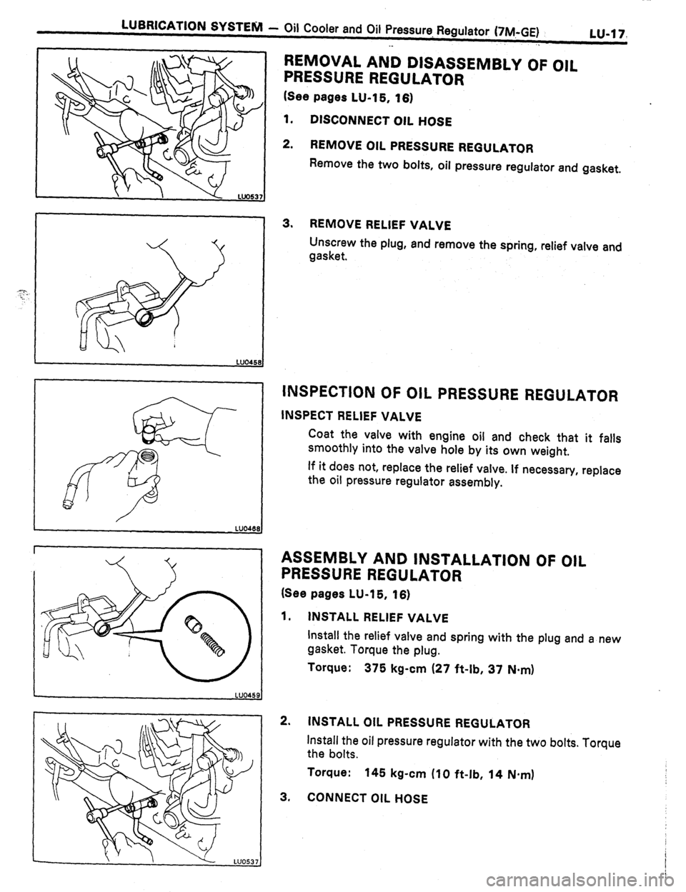
REMOVAL AND DISASSEMBLY OF OIL
PRESSURE REGULATOR
(See pages LU-15, 16)
1. DISCONNECT OIL HOSE
2. REMOVE OIL PRESSURE REGULATOR
Remove the two bolts, oil pressure regulator and gasket.
3. REMOVE RELIEF VALVE
Unscrew the plug, and remove the spring, relief valve and
gasket.
INSPECTION OF OIL PRESSURE REGULATOR
INSPECT RELIEF VALVE
Coat the valve with engine oil and check that it falls
smoothly into the valve hole by its own weight.
If it does not, replace the relief valve. If necessary, replace
the oil pressure regulator assembly.
ASSEMBLY AND INSTALLATION OF OIL
PRESSURE REGULATOR
(See pages LU-15, 16)
1. INSTALL RELIEF VALVE
Install the relief valve and spring with the plug and a new
gasket. Torque the plug.
Torque:
375 kg-cm (27 ft-lb, 37 N-m)
2. INSTALL OIL PRESSURE REGULATOR
Install the oil pressure regulator with the two bolts. Torque
the bolts.
Torque:
145 kg-cm (10 ft-lb, 14 N.m)
3, CONNECT OIL HOSE
Page 301 of 346
LUBRICATION SYSTENI - Oil Cooler and Oil Pressurr+ Regulator (7M-GTE)
’ 1” - 06Lu-19
---. “, -“-~~yII.
. .
INSPECTION OF RELIEF VALVE
Coat the valve with engine oil and check that it falls
smoothly into the valve hole by its own weight.
If it does not, replace the relief valve. If necessary,
replace
the oil filter bracket assembly.
INSTALLATION OF OIL ASSEMBLY AND
FILTER BRACKET
(See page LU-18)
1. INSTALL RELIEF VALVE
(a) Install the relief valve and spring.
(b) Install and torque the plug with a new gasket.
Torque: 375 kg-cm (27 ft-lb, 37 Nsm)
2.
INSTALL OIL FILTER
(See page LU-8)
3. INSTALL OIL FILTER BRACKET
(a) Install a new O-ring to bracket.
(b) Install a new gasket to union bolt.
(c) Put the oil filter bracket hole over the cylinder block
stud bolt and install the oil filter bracket with the
union bolt.
(d) Torque the union bolt.
Torque: 500 kg-cm (36’ ft-lb, 49 N*mI
Page 337 of 346
TURBOCHARGER SYSTEM -’ iurbqcharger
-. TC-8
COMPONENTS
No. 1 Turbo Water Hose
I,
No. 1 Turbo Water Pipe
I
No. 2 Turbocharger Stay -s&z .‘I,,
”
Turbo Heat insulator Turbine dutlet Elba
Turbocharger Stay
]kg-cm (ft-lb, N.rn)l : Specified torque
+ Non-reusable part
Page 342 of 346

tc-14 TURBOCHARGER SYSTEM -’ Turbocharger
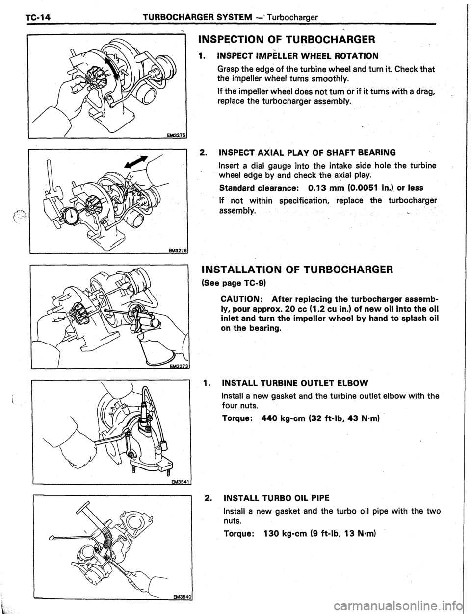
INSPECTION OF TURBOCHARGER
INSPECT IMPELLER WHEEL ROTATION 1.
Grasp the edge of the turbine wheel and turn it. Check that
the impeller wheel turns smoothly.
If the impeller wheel does not turn or if it turns with a drag,
replace the turbocharger assembly. ,
2.
INSPECT AXIAL PLAY OF SHAFT BEARING
Insert a dial gauge into the intake side hole the turbine
wheel edge by and check the axial play.
Standard clearance: 0.13 mm (O.OOBl in.). or less
If not within specification, replace the turbocharger
assembly.
i.
v
EM32761
INSTALLATION OF TURBOCHARGER
(See page TC-9)
CAUTION: After replacing the turbocharger assemb-
ly, pour approx. 20 cc (1.2 cu in.) of new oil into the oil
inlet and turn the impeller wheel by hand to splash oil
on the bearing.
1. INSTALL TURBINE OUTLET ELBOW
install a new gasket and the turbine outlet elbow with the
four nuts.
Torque: 440 kg-cm (32 ft-lb, 43 N-m) i
2.
INSTALL TURBO OIL PIPE
Install a new gasket and the turbo oil pipe with the two
nuts.
Torque: 130 kg-cm (9 ft-lb, 13 N.m)
Page 343 of 346
SYSTEM -
Turbocharger
TC-15
3.
INSTALL NO.l. TURBO WATER PIPE
Install a new gasket and the No.1 turbo water pipe with
the two nuts.
Torque: 75 kg-cm (65 in.-lb, .7.4 Nom)
4.
INSTALL TURBOCHARGER
(a) Face the new gasket so the protrusion is facing the
rear and install on the exhaust manifold.
(b) Place a new gasket on the oil return hole of the
cylinder block.
(c) Install the turbocharger through the turbocharger
stud bolts and turbo oil pipe stud bolts.
(d) Temporarily install the four nuts holding the exhaust
manifold and turbocharger.
(e) Temporarily install the turbo oil pipe flange nuts.
(f) %rk;;Trily install the union bolt with two new
(g) Torque the turbocharger mounting nuts.
. Torque: 450 kg-cm (33 f?-lb, 44 N-m)
(h) Torque the turbo oil pipe union bolt and flange nuts.
Torque:
Bolt 350 kg-cm (25 ft-lb, 34 N-m)
Nut 130 kg-cm (9 ft-lb, 13 N-m)