Page 221 of 346

ENGINE MECHANICAL - CylinderHead
EM&Q
C Front
EX
EM300’
:
‘INSTALLATl.QN’OF CYLINDER
(See pages EM-37, 38)
1. INSTALL CYLINDER HEAD
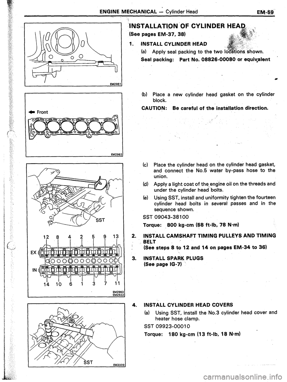
(a) Apply seal packing to the two i
Seal packing: Part No. 08826-00080 or equiyafent
(b) Place a new cylinder head gasket on the cylinder
block.
CAUTION: Be careful of the’installation direction.
!
(c) Place the cylinder head on the cylinder head gasket,
and connect the No.5 water by-pass hose to the
union.
Id) Apply a light coat of the.,engine oil on the threads and
under the cylinder head ‘bolts.
(e) Using SST, install and uniformity tighten the fourteen
cylinder head bolts. in several passes and in the
sequence shown.
SST 09043-38 100
Torque: >800 kg-cm (E8 ft-lb, 78 N=m)
2.
3.
4. INSTALL CAMSHAFT TIMING PULLEYS AND TIMING
BELT ’
(See steps 8 to 12 and 14 on pages EM-34 to 36)
INSTALL SPARK PLUGS
(See page 16-71 ~
INSTALL CYLINDER HEAD COVERS
(a) Using SST, install the No.3 cylinder head cover and
heater hose clamp.
SST 09923-00010 in.
Torque: 180 kg-cm (13 ft-lb, 18 N.m)
Page 228 of 346

EM-66 ENGINE MECHANICAL - Cylinder Block
_. DISASSEMBLY OF CYLINDER BLOCK
(See page EM-651
1. REMOVE FLYWHEEL OR DRIVE PLATE AND REAR
END PLATE
2. INSTALL ENGINE STAND FOR DISASSEMBLY
3. REMOVE TIMING BELT
(See steps 2 to 8 and 10 to 18 on pages EM-28 to 31)
4. REMOVE CYLINDER HEAD .I
(See steps 1 to 15 and 18 on pages EM-39 to 43)
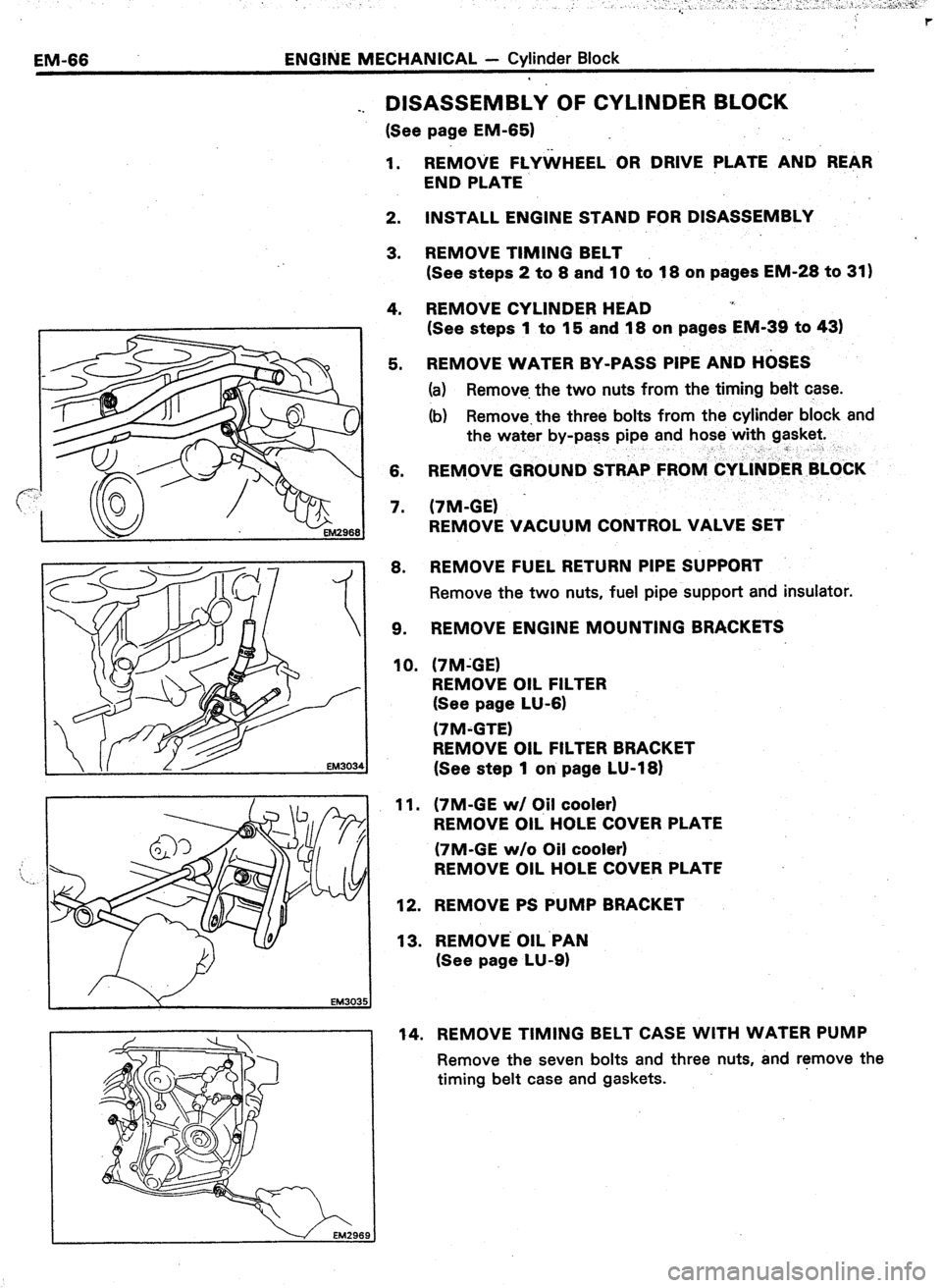
5. REMOVE WATER BY-PASS PIPE AND H&ES
(a) Remove. the two nuts from the timing belt case.
(b) Remove.the three bolts from the cylinder block and
the water by-pass pipe and hose with gasket.
__” r
6. REMOVE GROUND STRAP FROlV&Y~l~tiER BLOkK
7. (7M-GE) -
REMOVE VACUUM CONTROL VALVE SET
8. REMOVE FUEL RETURN PIPE SUPPORT
Remove the two nuts, fuel pipe support and insulator.
9. REMOVE ENGINE MOUNTING BRACKETS
10. (‘IM-GE)
REMOVE OIL FILTER
(See page LU-6)
(7M-GTE)
REMOVE OIL FILTER BRACKET
(See step 1 on page LU-18)
11.
12.
13. (7M-GE w/ C#l cooler)
REMOVE OIL HOLE COVER PLATE
(7M-GE w/o Oil cooler)
REMOVE OIL HOLE COVER PLATE
REMOVE PS PUMP BRACKET
REMOVE OIL.PAN
(See page LU-9)
14. REMOVE TIMING BELT CASE WITH WATER PUMP
Remove the seven bolts and three nuts, and r!move the
timing belt case and gaskets.
Page 248 of 346
EM-86
,, ENGINE MF@ANl,CAL - Cjrlinder Block
EM456:
?==--zpe EM0262 EM1 761
3. REPLACE PUM+ DRIVE SHAFT OIL SEAL
A. If the timing b&t case is removed from the
cyjinder block:
(a) Using a screwdriver and hammer, tap out the oil seal.
(b) Using SST and a hammer, tap in a new oil seal.
SST 09214-41ClO C
, . . .
(c) Apply MP grease to the oil seal, lip.
A--
*- .
& If the timing belt case is installed to the cylinder
block:
(a) Using a knife, cut off the lip of the oil seal as shown.
(b) Using a screwdriver, pry .out the oil seal.
CAUTION: Be careful not
to damage the crankshaft.
Tape the screwdriver tip.
(c) Check the oil seal lip contact surface of the pump
drive shaft for cracks or damage.
(d) Apply MP grease to a new oil seal lip.
(e) Using SST and a hammer, tap in the oil seal.
SST 09214-41010
Page 253 of 346
ENGINE MECHANICAL - Cylinder Block
Qy g&
.
e. .-. .a ,j .a. VI ,... :~.~.**-.-. ),
9. INSTALL OIL PUMP DRIVE SHAFT
(a) While turning the drive shaft, insert slowly to avoid
damaging the drive shaft bearing.
(b) Install the bolt.
Torque:
145 kg-cm (10 ft-lb, 14 N*m)
10. INSTALL REAR OIL SEAL RETAINER
Install
a new gasket and rear oil seal retainer with the five
bolts.
Torque: 130 kg-cm (9 ft-lb, 13 N.m)
11. INSTALL TIMING BELT CASE WITH WATER PUMP
(a) Position new
gaskets on the cylinder block.
(b) Apply sealant to two or three threads of the 10 mm
bolt end.
Sealant: Part No. 08833-00070, THREE BOND 1324
or equivalent
(c) Install the timing belt case with the seven bolts and
three nuts.
12. INSTALL OIL PAN
(See page LU-14)
.13. INSTALL PS PUMP BRACKET
Page 254 of 346

EM-92 _. ENGINE MECHANICAL +’ Cylinder Block
-..
: .
;,,
“.’
‘i4. (7M-GE w/ Oil Cooler)
INSTALL Oil.. REGULATOR
Install a new gasket and oil regulator with. the two bolts.
(7M-GE w/o Oil Cooler and.7M-GTE)
INSTALL OIL HOLE COVER PLATE
Install a new gasket and oil hole cover plate with the two .
bolts.
15. (7M-GE)
INSTALL NEW OIL FILTER
(See page LU-6)
16. INSTALL ENGlNE MOUNTING BRACKETS
17. INSTALL FUEL RETURN PIPE SUPPORT
Install a new insulator and fuel pipe support with the two
nuts. :
Torque: 130 kg-cm (69 ft-lb, ‘1.3 N&l
18. (7M-GE)
INSTALL VACUUM CONTROL VALVE SET
19. INSTALL GROUND STRAP TO CYLI’NDER BLOCK
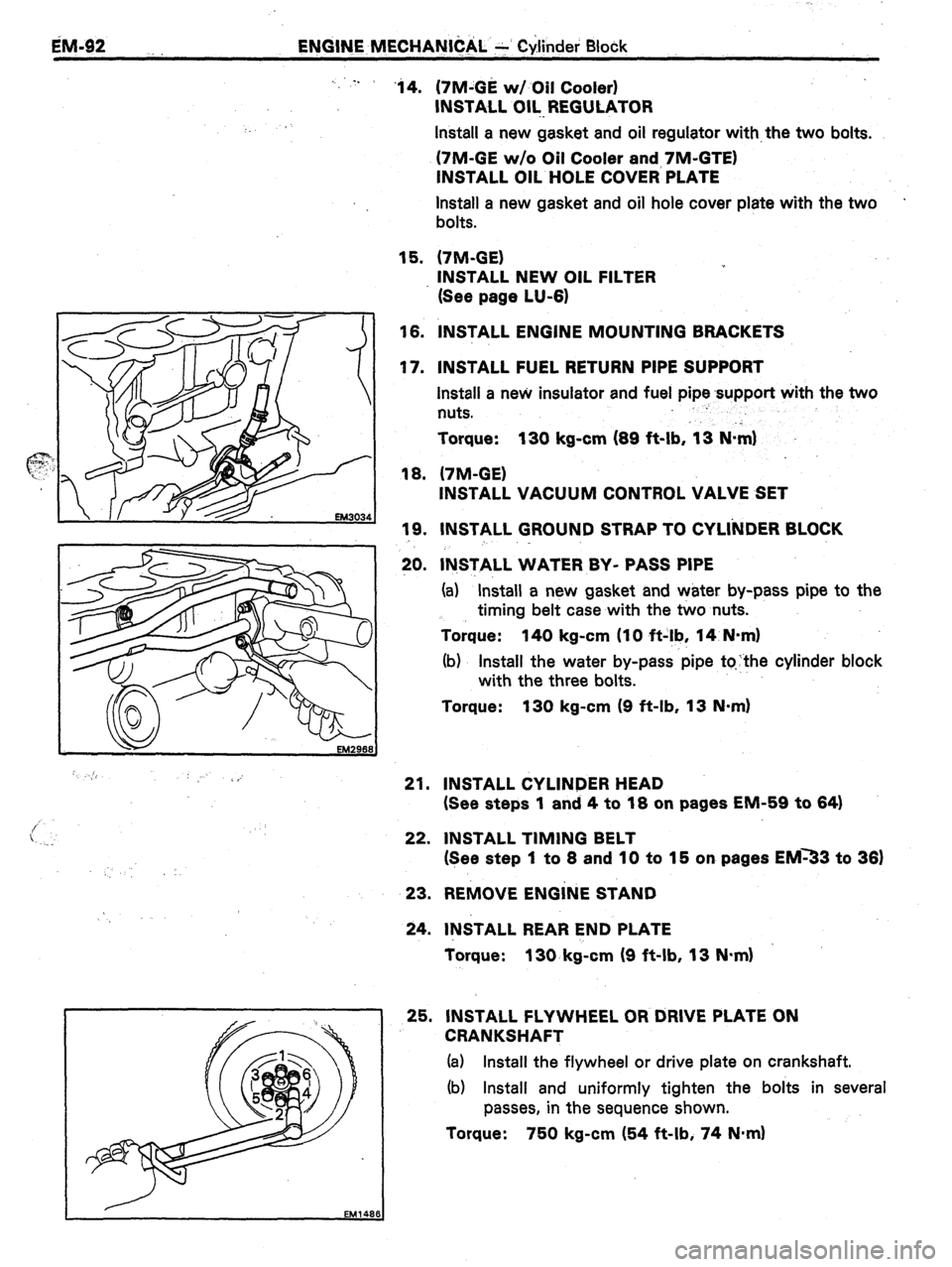
20. lN,STALL WATER BY- PASS PIPE
(a) “Install a new gasket and water by-pass pipe to the
timing belt case with the two nuts.
Torque: 140 kg-cm (IO ft-!b, 14 N-m)
(b) Install the water by-pass pipe tqthe cylinder block
with the three bolts.
Torque: 130 kg-cm (9 ft-lb, 13 N-m)
21. INSTALL CYLINDER HEAD
(See steps 1 and 4 to 18 on pages EM-59 to 64)
22. INSTALL TIMING BELT
(See step 1 to 8 and 10 to 15 on pages EM33 to 36)
23. REMOVE ENGiNE STAND
24. INSTALL REAR END PLATE
Torque: 130. kg-cm (9 ft-lb, 13 N.m)
25. INSTALL FLYWHEEL OR DRIVE PLATE ON
CRANKSHAFT
(a) Install the flywheel or drive plate on crankshaft.
(b) Install and uniformly tighten the bolts in several
passes, in the sequence shown.
Torque: 750 kg-cm (54 ft-lb, 74 N*m)
Page 274 of 346
16-20
ION ITION SYSTEM
- Distiibtitor ‘(7M-GE)
(c) .; Ttirq the crankshaft counterclockwise approximate
1 :
1 2o”.
Id) Turn-the crankshaft again approximately 10” to
4~
clockwise so that the timing belt cover TDC mark ar!
the crankshaft pull&y TDC mark are aligned.
/
IG06C
5. REMOVE DISTRIBUTOR
(a) Remove
;he hold-down bolt,
(b) Pull out the distributor from the cylinder head.
6. REMOVE O-RING
Page 278 of 346
IQ-24 IGNITION SYSTEM - Cam Position Sensor (7M-GTE)
(cl y2;dthe crankshaft counterclockwise arjproximately
(d) Turn the crankshaft again approximtiteli 10” to 40”
clockwise so that the timing belt cove; TDC mark and
the crankshaft pulley TDC mark are aligned.
.
4. REMOVE NO.4 AIR CLEANER PIPE WITH NO.1 PND
NO.2 AIR CLEANER HOSES
5.
REMOVE NO.7 AIR CLEANER HOSE WITH AIR FLOW
METER AND AIR CLEANER CAP
(a) Disconnect the three air hoses and PCV hose.
(b) Disconnect the air flow meter connector.
(c) Disconnect the PS idle up air hose.
(d) Loosen the clamps and remove the bolt.
(e) Remove the No.2 air cleaner hose with air flow meter
and air cleaner cap.
6.
REMOVE PS RESERVOIR TANK
Remove the two bolts, nut and reservoir tank with bracket.
Page:
< prev 1-8 9-16 17-24