1987 TOYOTA CELICA oil type
[x] Cancel search: oil typePage 23 of 346
. COOLING SYSTEM - Description
co;3
RESERVOIR TANK
The reservoir tank is used to catch coolant
which overflows the cooling systein as a result of
volumetric expansion when the coolant is heated.
The coolant in the reservoir tank returns to the
radiator when the coolant temperature drops, thus
keeping the radiator full at all times and avoiding
needless coolant loss. Check the reservoir tank
level to learn if the coolant needs to be rep-
lenished.
WATER PUMP
The water pump is used for forced circulation of
coolant through the cooling system. It is mounted
on the front of the cylinder block and driven by a
V-ribbed belt,
THERMOSTAT I The cooling system is composed of the water
jacket (inside the cylinder block and cylinder head),
radiator, water pump, thermostat, cooling fan,
hoses and other components.
Coolant which is heated in the water
jacket is
pumped to the radiator, through which a cooling
fan blows air to cool the coolant as it passes
through. Coolant which has been cooled is then
sent back to the engine by the water pump, where
it cools the engine.
The water jacket is a network of channels in the
shell of the cylinder block and cylinder head
through which coolant passes. It is designed to
provide adequate cooling of the cylinders are com-
bustion chambers which become the hottest dur-
ing engine operation.
F(/ “ IATOR
The radiator performs the function of cooling
the coolant which has passed through the water
jacket and become hot, and is mounted in the front
of the vehicle. The radiator consists of an upper
tank and ‘lower tank, and a core which connects
the two tanks. The upper tank contains the inlet for
coolant from the water jacket and the filter inlet. It
also has a hose attached through which excess
coolant or steam can flow. The lower tank contains
the outlet for coolant and the drain cock. The core
contains many tubes through which coolant flows
from the upper tank to the lower tank as well as
cooling fins which radiate heat away from the coo-
lant in the tubes. The air sucked through the radia-
tor by cooling fan, as well as the wind generated
by the vehicle’s travel, passes through the radia-
tor, cooling it. Models with automatic transmission
incrl*-le an automatic transmission fluid cooler built
in:.
.le lower tank of the radiator.
RADIATOR CAP
The radiator cap is a pressure type can which
seals the radiator, resulting in pressurization of the
radiator as the coolant expands. The pressuriza-
tion prevents the coolant from boiling even when
the coolant temperature exceeds 100°C. A relief
valve (pressurization valve) and a vacuum valve
(negative pressure valve) are built into the radiator
zap. The relief valve opens and lets steam escape
:hrough the overflow pipe when the pressure
3enerated inside the cooling system exceeds the
imit (coolant temperature:
110 - 1 20°C, (230
- 248”F), pressure; 0.3 - 1 .O kg/cmz, (4.3 - 14.2
)si, 29.4 - 98.1 kPa). The vacuum valve opens to
3ljeviate the vacuum which develops in the coolant
system after the engine is stopped and the coolant
emperature drops. The valve’s opening allows the
)ressure in the cooling system to return to the
Qclant in the reservoir tank. The thermostat has a wax type and is mounted
in the. water outlet housing. The thermostat
includes a type of automatic valve operated by
fluctuations in the coolant temperature. This valve
closes when the coolant temperature drops, pre-
venting the circulation of coolant through the
engine and thus permitting the engine to warm up
rapidly. The valve opens when the coolant tem-
perature has risen, allowing the circulation of coo-
lant. Wax inside the thermostat expands when
heated and contracts when cooled. Heating the
wax thus generates pressure which overpowers
the force of the spring which keeps the valve
closed, thus opening the valve. When the wax
cools, its contraction causes the force of the
spring to take effect once more, closing the valve.
The thermostat in this engine operates at a tem-
perature of 88”C(19O”F).
I
I
Page 44 of 346
FI-10 EFI SYSTEM - inspection Precautions
L Fco97 FlOO91
I
. FI159
i. 4 Gasket
New
‘Gasket
I / FM067 FHOE
Fulcrum Length
19
54
-.
(b) insert the tester probe into the connector from the
wiring side when-checking the continuity,,amperage
L
or voltage.
(c) Do not apply unnecessary force to the terminal.
(d) After checking, install the water-proofing rubber on
the connector securely.
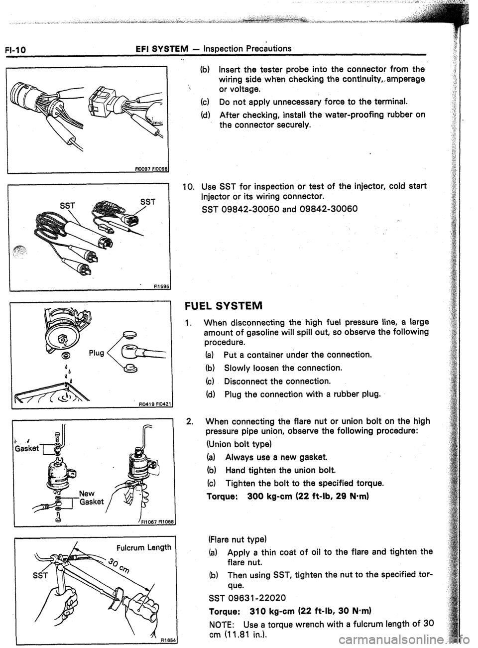
10. Use SST for inspection or test of the injector, cold start
injector or its wiring connector.
SST 09842-30050 and 09842-30060
FUEL SYSTEM
1.
2. When disconnecting the high fuel pressure line, a large
amount of gasoline will spill out, so observe the following
procedure.
(a) Put a container under the connection.
(b) Slowly loosen the connection.
(c) Disconnect the connection.
(d) Plug the connection with a rubber plug.
When connecting the flare nut or union bolt on the high
pressure pipe union, observe the following procedure:
(Union bolt type)
(a) Always use a new gasket.
(b) Hand tighten the union bolt.
(c) Tighten the bolt to the specified torque.
Torque: 300 kg-cm (22 it-lb, 29 N*m)
(Flare nut type)
(a) Apply a thin coat of oil to the flare and tighten the
flare nut.
(b) Then using SST, tighten the nut to the specified tor-
que.
SST 09631-22020
Torque: 310 kg-cm (22 ft-lb, 30 N*m)
NOTE: Use a torque wrench with a fulcrum length of 30
cm (11.81 in.).
Page 48 of 346
EFI SYSTEM - Troubleshootina
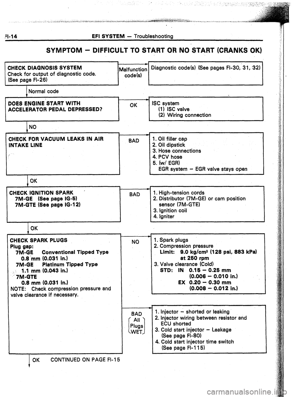
SYMPTOM - DIFFICULT TO START O-R NO START (CRANKS OK)
CHECK DIAGNOSIS SYSTEM
Check for output of diagnostic code.
(See page FI-26) Diagnostic code(s) (See pages FI-30,‘31,32)
Normal code
DOES ENGINE’START WITH
ACCELERATORPEDALDEPRESSED? OK ISC system
0) ISC valve
(2) Wiring connection
i NO I
CHECK FOR VACUUM LEAKS IN AIR I
BAD
INTAKE LINE
I OK
CHECK IGNITION SPARK ’
7M-GE (See page IO-61
7M-GTE (See page IG-12)
t OK
CHECKSPARKPLUGS
Plug gap:
7M-GE Conventional Tipped Type
0.8 ‘mm (0.031 In.)
7M-GE Platinum Tipped Type
: : 1.1 mm (0.043~in.)
.7M-GTE
0.8 mm (0.031 In.)
NOTE: Check compression pressure and
valve clearance if necessary.
OK CONTINUED ON PAGE FI-15
!
I
.
BAD 1. Oil filler cap
2. Oil dipstick
3. Hose connections
4. PCV hose
5. (w/ EGR)
EGR system - EGR valve stays open
1. High-tension cords
2. Distributor (‘IM-GE) or cam position
sensor (7M-GTE)
3. Ignition coil
4. Igniter
+
NO
BAD 1. Spark plugs
2. Compression pressure
Limit: 9.0 kg/cm2 (128 psi, 883 kPa)
at 250 rpm
3. Valve clearance (Cold)
STD: IN 0.16 - 0.25 mm
(0.008 - 0.010 in.)
EX 0.20 - 0.30 mm
(0.008 - 0.012 in.1
1. Injector - shorted or leaking
2. Injector wiring between resistor and
ECU shorted
3. Cold start injector - Leakage
(See page Fl-80)
4. Cold start injector time switch
(See page Fl-115)
Page 50 of 346
l-16 EFI SYSTEM - Troubleshooting
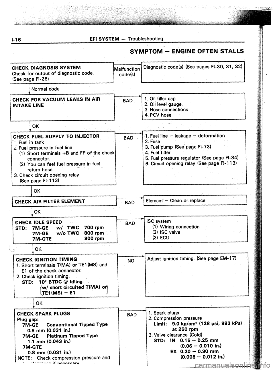
SYMPTOM - ENGINE OFTEN STALLS
CHECK DIAGNOSIS SYSTEM
Check for output of diagnostic code.
(See page Fl-26) * Diagnostic code(s) (See pages FI-30, 31, 32)
Malfunction
code(s)
Normal code
CHECK FOR VACUUM LEAKS IN AIR
INTAKE LINE BAD 1. Oil filler cap
2. Oil level gauge
3. Hose connections
4. PCV hose
I OK
CHECK FUEL SUPPLY TO INJECTOR
‘*-- Fuel in tank BAD
L. Fuel pressure in fuel line
(1) Short terminals +B and FP of the check
connector.
(2) You can feel fuel pressure in fuel
return hose. .
3. Check circuit opening relay
(See page FI-113) .
1. Fuel line - leakage - deformation
2. Fuse
3. Fuel.pump (See’ page FI-73)
4. Fuel filter
5. Fuel pressure regulator (See page FI-84)
6. Circuit opening relay (See page FI:1 13).
,
OK
CHECK AIR FILTER
I BAD Element - Clean or replace
OK
CHECK IDLE SPEED
STD: 7M-GE wl TWC 700 rpm
7M-GE w/o TWC 800 rpm
7M-GTE 800 rpm
t w
BAD ISC system
(I 1 Wiring connection
(21 ISC valve
(3) ECU
CHECK IGNITION TIMING ‘-
‘I. Short terminals TiMA) or TEl (MS) and
El of the check connector..
2. Check ignition timing.
STD: 10” BTDC @ Idling
short circuited T(MA) or
1
OK
CHECK SPARK PLUGS
Plug gap:
7M-GE Conventional Tipped Type
0.8 mm (0.031 in.)
7M-GE Platinum Tipped Type
1.1 mm (0.043 in.)
7M-GTE
0.8 mm (0.031 in.)
NOTE: Check compression pressure and
-I------- :+ -nyrpCCpn, c
NO
-I-
BAD - Adjust ignition timing. (See page EM-1 7)
1. Spark plugs
2. Compression pressure
Limit: 9.0 kg/cm2 (128 psi, 883
kPa)
at 250 rpm
3. Valve clearance (Cold)
STD: IN 0.15 - 0.25 mm
(0.06 - 0.010 in.)
Page 52 of 346
a EFI SYSTEM - Troubleshooting
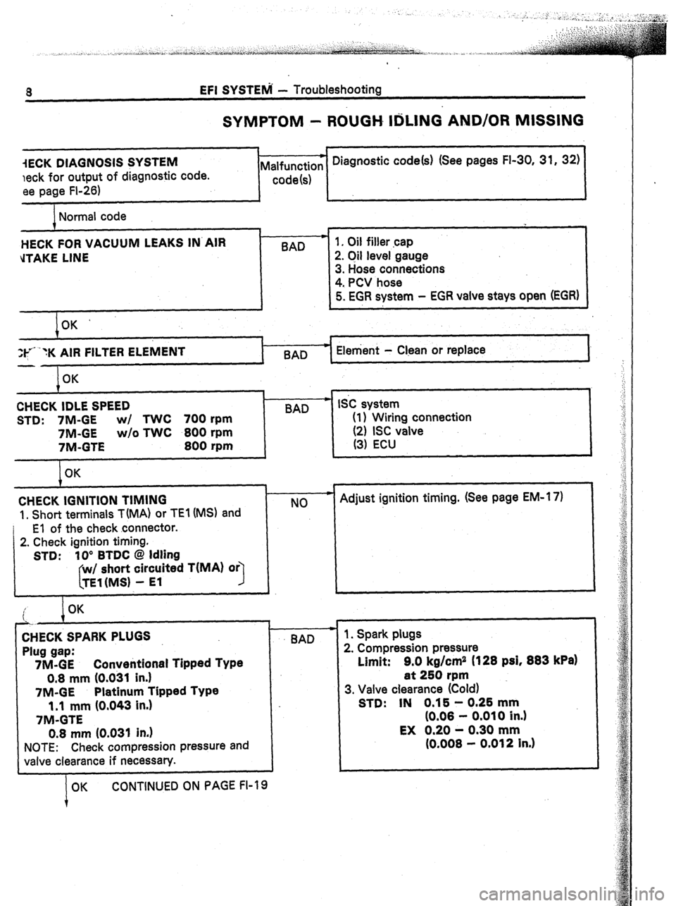
SYMPTOM - ROUGH IrIiLlNG AND/OR MISSING
iECK DIAGNOSIS SYSTEM
leek for output of diagnostic code.
ee page FI-26)
1 -c Diagnostic code(s) (See pages FI-30, 31, 32)
Malfunction
code(s)
Normal code
HECK FOR VACUUM LEAKS IN’AIR
d-FAKE LINE
I OK’
If* “K AIR FILTER
ELEMENT Element - Clean or replace
I
I 1, Oil filler cap
2. Oil level gauge
3. Hose connections
4. PCV hose
5. EGR system - EGR vaive stays open (EGR)
OK
CHECK IDLE SPEED
STD: 7M-GE w/ TWC 700 rpm
7M-GE w/o TWC 800 rpm
7M-GTE
800 rpm
OK
,
BAD SC system
(1) Wiring connection
(2) ISC valve
(3) ECU
CHECK IGNITION TIMING
1, Short terminals T(MA) or TEI (MS) and
El of the check connector.
2. Check ignition timing.
STD: IO” BTDC @ Idling
w/ short circuited T(MA)
I TEl(MS1 - El NO F Adjust ignition timing. (See page EM-l 7)
i OK
‘.
7
I
CHECK SPARK PLUGS
Plug gap:
7M-GE Converitional Tipped Type
0.8 mm (0.031 in.)
7M-GE Platinum Tipped Type
1.1 mm (0,043 in.)
7M-GTE
0.8 mm (0.031 in.)
NOTE: Check compression pressure and
valve clearance if necessary.
OK CONTINUED ON PAGE FI-19 BAD 1. Spark plugs
2. Compression pressure
Limit: 9.0 kg/cm2 (128 psi, 883
kPa)
at 250 rpm
3. Valve clearance (Cold)
STD: IN 0.15 - 0.25 mm
(0.08 - 0.010 in.)
EX 0.20 - 0.30 mm
(0.008 - 0.012 in.)
Page 113 of 346
EFI SYSTEM - Fuel System
FI-79
. .
/
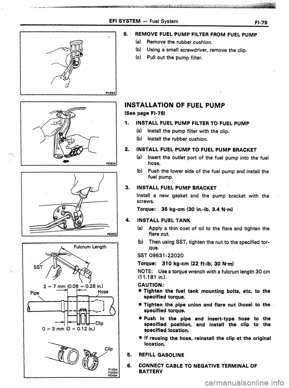
A Fulcrum Length
2 - 7 mm (0.08 1 0.28 in.)
Pipe Hose
k ’
em -m-d-‘,
--
0 - 3 mm (0 - 0.12 in.) 6. REMOVE FUEL PUMP FILTER FROM FUEL PUMP
(a) Remove the rubber cushion.
(b) Using a‘small screwdriver, remove the clip.
(4 Pull out the pump filter.
INSTALLATION OF FUEL PUMP
(See page Fi-78)
1.
2. INSTALL FUEL PUMP FILTER TO FUEL PUMP
(a) Install’the pump filter with the clip.
(b) install the rubber cushion.
INSTALL FUEL PUMP TO FUEL PUMP BRACKET
(a) Insert the outlet port of the fuel pump into the fuel
hose.
(b) Push the lower side of the fuel pump and install the
fuel pump.
3. INSTALL FUEL PUMP BRACKET
Install a new gasket and the pump bracket with the
screws.
Torque: 35 kg-cm (30 in-lb, 3.4 N-m)
4.
INSTALL FUEL TANK
(a) Apply a thin coat of oil to the flare and tighten the
flare nut.
(b) Then using SST, tighten the nut to the specified tor-
que.
SST 09631~22020
Torque: 310 kg-cm (22 ft-lb, 30 N-m)
NOTE: Use a torque wrench with a fulcrum length 30 cm
(1 1 .181 in.).
CAUTION:
l Tighten the fuel tank mounting bolts, etc. to the
specified torque.
l Tighten ‘the pipe union and flare nut (hose) to the
specified torque.
l Push in the pipe and insert-type hose to the
specified position, and install the clip to the
specified location.
l If reusing the hose, reinstall the clip at the original
location,
5. REFILL GASOLINE
6. CONNECT CABLE TO NEGATIVE TERMINAL OF
BATTERY
Page 165 of 346
ENGINE MECHANICAL -, Description
EM-3
The 7M-GE, 7M-GTE engines are an in-line 6-
cylinder engine with the cylinders numbered l-2-
3-4-5-6 from the front. The crankshaft is sup-
ported by 7 bearings specified by the inside of the
crankcase. These bearings are made of kelmet.
.The crankshaft is integrated with 8 weights
which are cast along with it for balancing. Oil holes
‘are built into the crankshaft for supplying oil to the
connecting rods, pistons and other components.
These engine’s ignition order is l-5-3-6-2-4 .
The cylinder head is made of aluminum alloy, with
a cross flow type intake and exhaust layout and
with pent roof type combustion chambers. The
spark plugs are located in the center of the com-
bustion chambers.
Exhaust and intake valves are equipped with
irregular pitch springs with symmetrical ends
made of oil tempered silicon chrome steel wire
which are capable of following the valves even at
,high engine speeds.
Both the exhaust side cam shaft and the. intake
side cam shaft are driven by a single timing belt.
The cam journal is supported at 7 places between
the valve lifters of each cylinder and on the
cylinder head of front end. Lubrication of the cam
journal and cam is accomplished by oil being sup-
plied through the oiler port in the center of the
camshaft.
Adjustment of the valve clearance is done by
means of an outer shim type system, in which
valve adjusting shims are located above the valve
lifters. This permits replacement of the shims
without removal of the camshafts.
The resin timing belt cover is made in 2 pieces.
Pistons are made of highly temperature-resis-
tant aluminum alloy, and depressions are built into
the piston head to prevent interference with
valves.
Piston pins are the full-floating type, with the
pins fastened to neither the piston boss nor the
connecting rods. Instead, snap rings are fitted on
both ends of the pins, preventing the pins from
falling out.
The No. 1 compression ring is made of stainless
steel and the No. 2 compression ring is made of
cast iron. The oil ring is made of a combination of
stainless steel. The outer diameter of each piston
ring is slightly larger than the diameter of the
piston
and the flexibility of the rings allows them
to hug the cylinder walls when they are mounted
on the piston. Compression rings No. 1 and No. 2
work to prevent the leakage of gas from the
cylinder and the oil ring works to scrape oil off the
cylinder walls to prevent it from entering the com-
bustion chamber.
The cylinder block is made of cast iron. It has 6
cylinders which are approximately 1.6 times the
length of the piston stroke. The top of the cylin- ders is closed off by the cylinder head and the
lower end of the cylinders becomes the crankcase,
in which the crankshaft is installed. In addition,- the
cylinder block contains a water jacket, through
which coolant is pumped to cool the cylinders.
The .oil pan is bolted onto the botiom of the
cylinder block. The oil pan is an oil reservoir made .
of pressed steel sheet. A dividing plate’is included
-inside the oil pan to keep sufficient oil in the bot-
tom of the pan even when the vehicle is tilted. This
dividing plate also prevent5 the oil from making
waves when the vehicle is stopped suddenly and
thus shifting the oil away from the oil pump suc-
tion pipe.
Page 284 of 346
LUBRICATION SYSTEM - Description
.,LU-3
A pressure feeding lubrication system has been
adopted to supply oil to the moving parts of this
engine. The lubrication system consists of an oil
pan, oil pump, oil filter and other external parts
which supply oil to the moving parts in the engine
block. The oil circuit is shown in the illustration at
the top of the previous page. Oil from the oil pan is
pumped up by the oil pump. After it passes
through the oil filter, it is fed through the various
oil holes in the crankshaft and cylinder block. After
passing through the cylinder block and performing
its lubricating function, the oil is returned by gra-
vity to the oil pan. A dipstick on the side of the
cylinder block is provided to check the oil level.
OIL PUMP
The oil pump pumps up oil from the oil pan and
sends it under pressure to the various parts of the
engine. An oil strainer is mounted in front of the
inlet to the oil pump. The oil pump itself is a gear
pump, which uses a drive gear and driven gear
inside the pump body. When the drive gear
rotates, the driven gear rotates in the opposite
direction. When the gear teeth disengage oil is
drak n in, and when the gear teeth engage oil is
discharged.
OIL PRESSURE REGULATOR
At high engine speeds, the engine oil supplied
bY thr oil pump exceeds the capacity of the engine
10 utiiize it.
For that reason, the oil pressure regula-
tor i ,>rks to prevent an oversupply of oil. During
norm.tl oil
supply, a coil spring and valve keep the
bYPcls:s closed, but when too much oil is being fed,
the I’tt’essure becomes extremely high, overpower-
9 the force of the spring and opening the valves.
This ;:ilows the excess oil to flow through the
Yalvtj :snd return to the oil pan. Olii FILTER
The oil filter is a full flow type filter with a built-
in paper filter element. Particles of :metal ‘from
wear, a&born dirt, carbon and other impurities can ’
get in the oil during use and could cause acceler-
ated wear or siezing if allowed to circulate through
the engine. The oil filter, integrated into the oil line,
removes these impurities as the oil passes through
it. The filter is mounted outside the engine to
simplify replacement of the filter element. A relief
valve is also included ahead of the filter element to
relieve the high oil pressure in case the filter ele-
ment becomes clogged with impurities. The relief
valve opens when the oil pressure overpowers the
force of the spring. Oil passing through the relief
valve bypasses the oil filter and flows directly into
the main oil hole in the engine.