Page 41 of 346

EFI SYSTEM
- Precautions, Inspection Precautions
FI-7
PRECAUTIONS
._
1. Before working on the fuel system, disconnect the
negative terminal from the battery.
NOTE: Any diagnosis code retained by the computer will
be erased when the battery terminal is removed.
Therefore, if necessary, read the diagnosis before
removimg the battery terminal.
2. Do not smoke or work near an open flame when work-
ing on the fuel system.
3. Keep gasoline off rubber or leather parts.
INSPECTION PRECAUTl.ONS
MAINTENANCE PRECAUTIONS
1. INSURE CORRECT ENGINE TUNE-UP
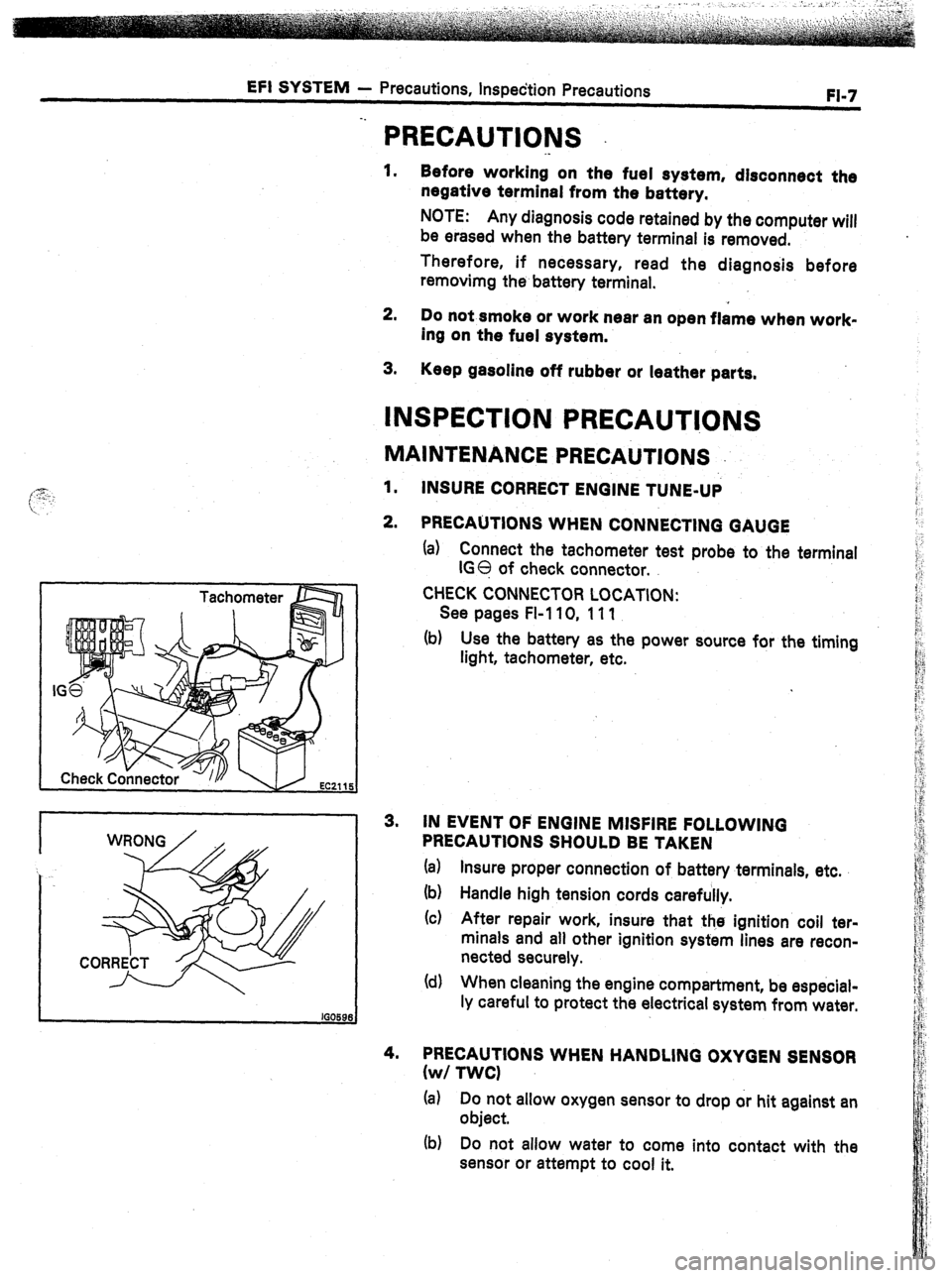
2. PRECAUTIONS WHEN CONNECTING GAUGE
(a) Connect the tachometer test probe to the terminal
IGO of check connector.
CHECK CONNECTOR LOCATION:
See pages FI-110, 111
(b) Use the battery as the power source for the timing
light, tachometer, etc.
3. IN EVENT OF ENGINE MISFIRE FOLLOWING
PRECAUTIONS SHOULD BE TAKEN
(a) Insure proper connection of battery terminals, etc.
(b) Handle high tension cords carefully.
(c) After repair work, insure that the ignition coil ter-
minals and all other ignition system lines are recon-
nected securely.
(d) When cleaning the engine compartment, be especial-
ly careful to protect the electrical system from water.
4. PRECAUTIONS WHEN HANDLING OXYGEN SENSOR
(w/ TWCI
(a) Do not allow oxygen sensor to drop or hit against an
object.
(b) Do not allow water to come into contact with the
sensor or attempt to cool it.
Page 108 of 346
‘I-74 EFI SYSTEM - Fuel System
Fl169
ON-VEHICLE INSPECTlOiU
1.
INSPECT FUEL PUMP OPERATION
(a) Turn the ignition switch to ON. :
NOTE: Do not start the engine.
(b) Using a service wire, short circuit the fuel pump
check terminals +B and FP of the check connector.
CHECK CONNECTOR LOCATION:
See pages FI-1 10, 111
(c) Check that there is pressure in the fuel return hose.
NOTE: At this time, you will hear fuel pressure noise.
(d) Remove the service wire.
(el Turn the ignition switch OFF.
If there is no pressure, check the following parts.
i Fusible links
0 Fuse
0 EFI main relay
0 Fuel pump
0 Wiring connections
2. INSPECT FUEL PRESSURE
(a) Check that battery voltage is above 11 bolts.
(b) Disconnect the cable from the negative (-) terminal
of the battery.
(c) Remove the cold start injector tube.
(7M-GE)
0 Disconnect the wiring connector from the cold
start injector.
Page 113 of 346

EFI SYSTEM - Fuel System
FI-79
. .
/
A Fulcrum Length
2 - 7 mm (0.08 1 0.28 in.)
Pipe Hose
k ’
em -m-d-‘,
--
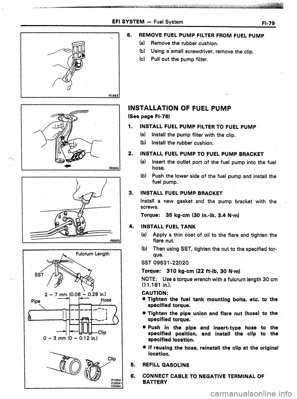
0 - 3 mm (0 - 0.12 in.) 6. REMOVE FUEL PUMP FILTER FROM FUEL PUMP
(a) Remove the rubber cushion.
(b) Using a‘small screwdriver, remove the clip.
(4 Pull out the pump filter.
INSTALLATION OF FUEL PUMP
(See page Fi-78)
1.
2. INSTALL FUEL PUMP FILTER TO FUEL PUMP
(a) Install’the pump filter with the clip.
(b) install the rubber cushion.
INSTALL FUEL PUMP TO FUEL PUMP BRACKET
(a) Insert the outlet port of the fuel pump into the fuel
hose.
(b) Push the lower side of the fuel pump and install the
fuel pump.
3. INSTALL FUEL PUMP BRACKET
Install a new gasket and the pump bracket with the
screws.
Torque: 35 kg-cm (30 in-lb, 3.4 N-m)
4.
INSTALL FUEL TANK
(a) Apply a thin coat of oil to the flare and tighten the
flare nut.
(b) Then using SST, tighten the nut to the specified tor-
que.
SST 09631~22020
Torque: 310 kg-cm (22 ft-lb, 30 N-m)
NOTE: Use a torque wrench with a fulcrum length 30 cm
(1 1 .181 in.).
CAUTION:
l Tighten the fuel tank mounting bolts, etc. to the
specified torque.
l Tighten ‘the pipe union and flare nut (hose) to the
specified torque.
l Push in the pipe and insert-type hose to the
specified position, and install the clip to the
specified location.
l If reusing the hose, reinstall the clip at the original
location,
5. REFILL GASOLINE
6. CONNECT CABLE TO NEGATIVE TERMINAL OF
BATTERY
Page 116 of 346
Fl-82 EFI SYSTEM - Fuel System
(d) Put a container under the injector.
(e) Reconnect the battery negative (-1 terminal.
(f) Turn the ignition switch ON.
NOTE: Do not start the engine.
Fl298:
!g) Using a service wire, short terminals +B and FP of
the check connector.
CHECK CONNECTOR LOCATION:
See pages ‘FI-j 10, 111
(h) Connect the test probes of the SST (wire) to the bat-
tery, and check that the fuel spray is as shown.
SST 09842-30050
CAUTION: Perform this check within the shortest
possible time.
2. INSPECT LEAKAGE
(a) In the condition above, disconnect the test probes of
SST (wire) from the battery and check fuel leakage
from the injector.
SST 09842-30050
Fuel drop: One drop or less per minute
(b) Disconnect the battery negative (-1 cable.
(c) Remove SST and the service wire.
SST 09268-41045 and 09842-30050
Page 125 of 346

EFI SYSTEM - Fuel System
FI-91
SST
(Hose)
Vinyl Tube
R167r
FP
+B
SST (Resistor Wire)
Graduated
Cylinder
Vinyl Tube
fllB'I
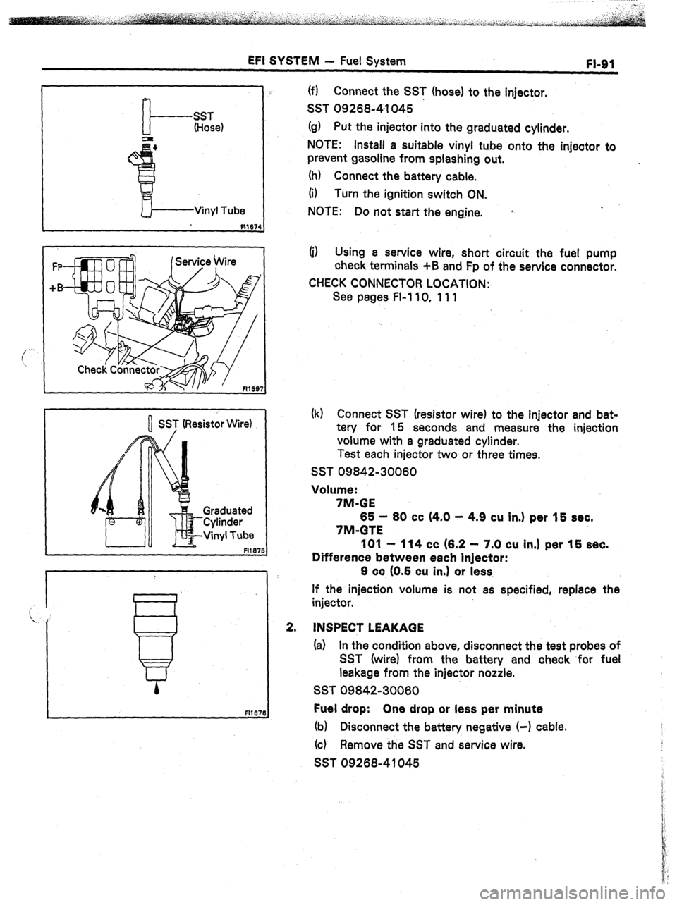
(f) Connect the SST (hose) to the injector.
SST 0926841045
(g) Put the injector into the graduated cylinder.
NOTE: Install a suitable vinyl tube onto the injector to
prevent gasoline from splashing out.
(h) Connect the battery cable.
(i) Turn the ignition switch ON.
NOTE: Do not start the engjne. *
(j) Using a service wire, short circuit the fuel pump
check terminals +B and Fp of the service connector.
CHECK CONNECTOR LOCATION:
Se6 pages Fl-110, 111
(k) Connect SST (resistor wire) to the injector and bat-
tery for 15 seconds and measure the injection
volume with a graduated cylinder.
Test each injector two or three times.
SST 09842-30060
Volume:
7M-GE
65 - 60 cc (4.0 - 4.9 cu in.) per 15 sec.
7M-GTE
101 - 114 cc (6.2 - 7.0 cu in.1 per 15 sec.
Difference between each injector:
9 cc (0.5 cu in.1 or less,
If the injection volume is not as specified, replace the
injector.
INSPECT LEAKAGE
(a) In the condition above, disconnect the test probes of
SST (wire) from the battery and check for fuel
leakage from the injector nozzle.
SST 09842-30060
Fuel drop: One drop or less per minute
(b) Disconnect the battery negative (-1 cable.
(c) Remove the SST and service wire.
SST 09268-41045
Page 256 of 346
16-2 IGNITION SYSTEM - precautions
-.
PRECAUTIONS
1.
2.
3.
4.
5.
6.
. *
Do not leave the ignition switch on for more than 10
minutes if the engine does not start.
When a tachometer is connected to the system; con-
nect the tachometer test probe to the check connector
terminal IG 0 .
CHECK CONNECTOR LOCATION:
See pages FI-110, 111
As some tachometers are not compatible with this
ignition system, we recommended that you confirm
the compatibility of your unit before using.
NEVER allow the tachometer terminals to touch
ground as it could result in damage to the igniter and/
or ignition coil.
Do not disconnect the battery while the engine is run-
ning.
Make sure that the igniter is properly grounded to the
body.
Page 328 of 346
STARTING SYSTEM
- Staher Relay (MS)
_. ., ST113
STARTER RELAY (MS)
._
INSPECTION OF STARTER RELAY
LOCATION:
partmen t. In the NO. 2 relay block of the engine com-
Continuity
Inl
Hi
0
0
0
-
Zontinuity
1.
INSPECT RELAY CONTINUITY
(a) Using an ohmmeter, check that there is continuity
lb) between terminals 1 and 3.
zt;cqk that there is no continuity between terminals 2
lf Continuity is not as specified, replace the relay.
2.
INSPECT RELAY OPERATION
(a) Apply battery voltage across terminals 1 and 3.
(b) Using an ohmmeter, check that there
is continuity
between terminals 2 and 4.
If operation is not as specified, replace the relay,