Page 46 of 346
1-12 EFI SYSTEM - Troubleshooting’
FlO48
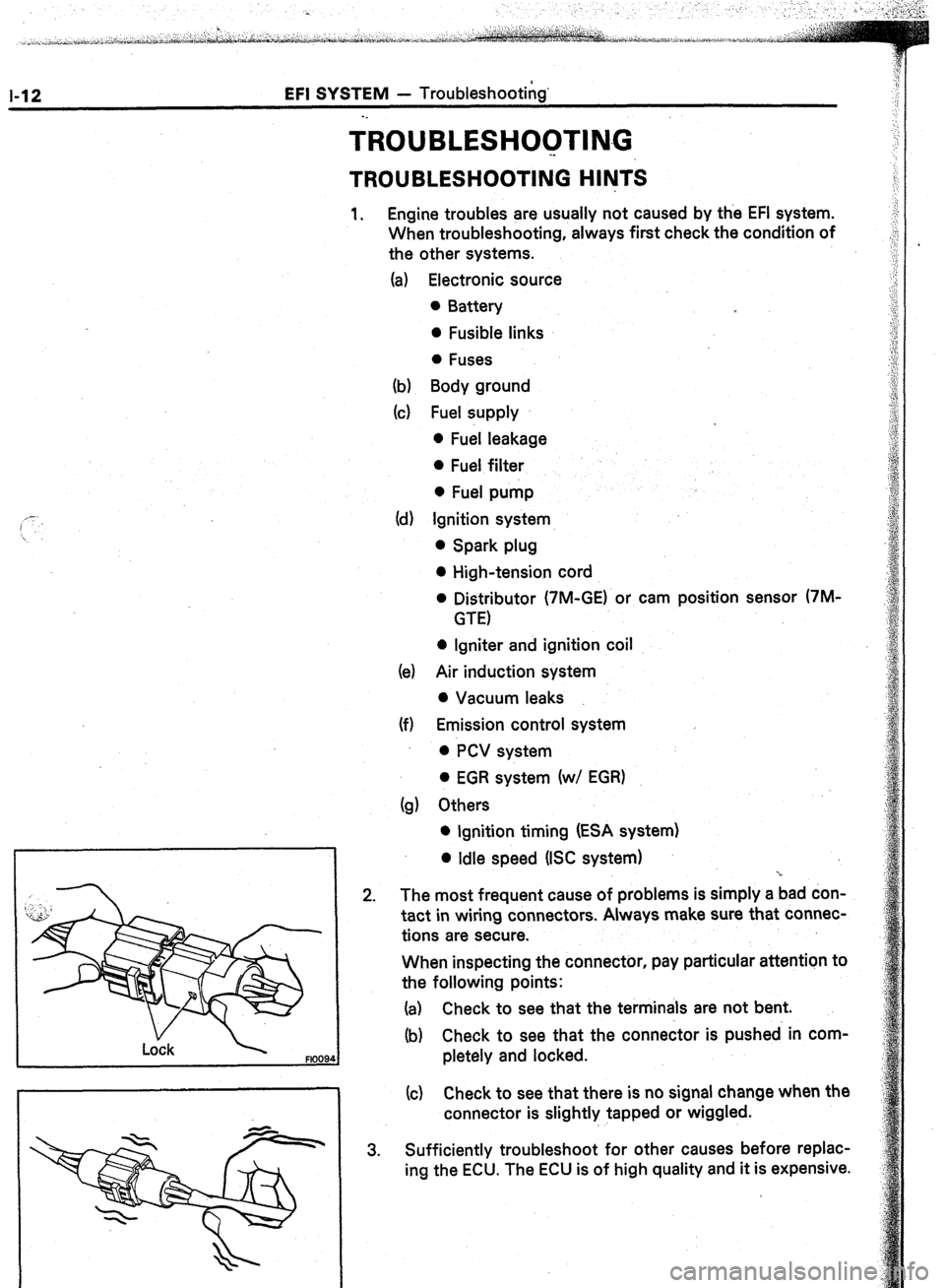
TROUBLESH~~TI~~G
. .
TROUBLESHOOTING HlhJTS
1. Engine troubles are usually not caused by the EFI system.
When troubleshooting, always first check the condition of
the other systems.
(a) Electronic source
0 Battery
0 Fusible links
0 Fuses
(b) Body ground
(cl Fuel supply
0 Fuel leakage
0 Fuel filter
0 Fuel pump
(d) Ignition system
0 Spark plug
0 High-tension cord
l Distributor (7M-GE) or cam position sensor (7M-
GTE)
0 Igniter and ignition coil
(e) Air induction system
0 Vacuum leaks
(f) Emission control system
0 PCV system
0 EGR system (w/ EGR)
(g) Others
l Ignition timing (ESA system)
0 Idle speed (ISC system)
-r
2. The most frequent cause of problems is simply a bad don-
tact in wiring connectors. Always make sure that connec-
tions are secure.
When inspecting the connector, pay particular attention to
the following points:
(a) Check to see that the terminals are not bent.
(b) Check to see that the connector is pushed in com-
pletely and locked.
(c) Check to see that there is no signal change when the
connector is slightly tapped or wiggled.
3. Sufficiently troubleshoot for other causes before replac-
ing the ECU. The ECU is of high quality and it is expensive.
Page 49 of 346
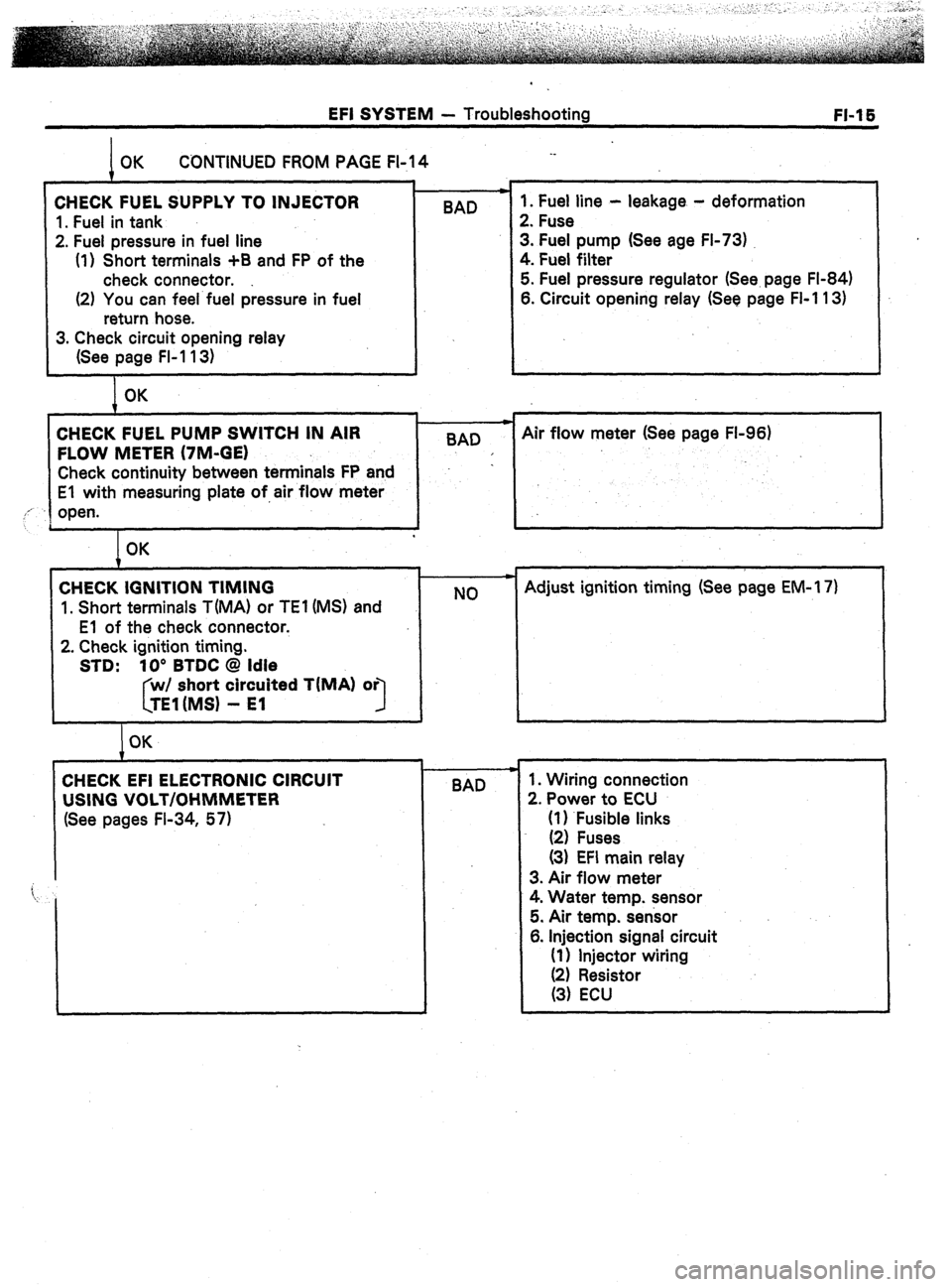
EFI SYSTEM - Troubleshooting
FI-1 E
CONTINUED FROM PAGE FI-14 ._
CHECK FUEL SUPPLY TO INJECTOR
1. Fuel in tank
2. Fuel pressure in fuel line
(1) Short terminals +B and FP of the
check connector.
(2) You can feel fuel pressure in fuel
return hose. BAD 1. Fuel line - leakage - deformation
2. Fuse
3. Fuel pump (See age FI-73)
4. Fuel filter
5. Fuel pressure regulator (See. page FI-84)
6. Circuit opening relay (See page FI-1 13)
3. Check circuit opening relay
(See page FI-1 13)
OK
CHECK FUEL PUMP SWITCH IN AIR
FLOW METER (7M-GE)
Check continuity between terminals FP and
El with measuring plate of,air flow meter
,,’
open.
L
I BAD c
Air flow meter (See page FL96)
I OK
CHECK IGNITION TIMING
1. Short terminals T(MA) or TEl (MS) and
El of the check connector.
2. Check ignition timing.
STD: 10’ BTDC @ Idle
short circuited TIMA) or
3
I OK NO Adjust ignition timing (See page EM-l 7)
BAD 1. Wiring connection
2. Power to ECU
(1) .Fusible links
(2) Fuses
(3) EFI main relay
3. Air flow meter
4. Water temp. sensor
5. Air temp. sensor
6. Injection signal circuit
(1) Injector wiring
Page 50 of 346
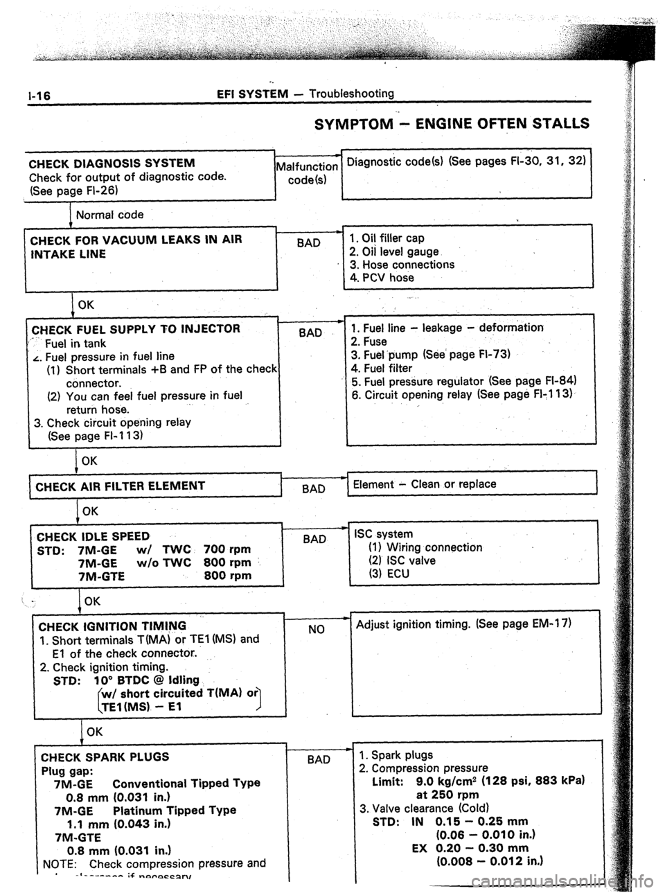
l-16 EFI SYSTEM - Troubleshooting
SYMPTOM - ENGINE OFTEN STALLS
CHECK DIAGNOSIS SYSTEM
Check for output of diagnostic code.
(See page Fl-26) * Diagnostic code(s) (See pages FI-30, 31, 32)
Malfunction
code(s)
Normal code
CHECK FOR VACUUM LEAKS IN AIR
INTAKE LINE BAD 1. Oil filler cap
2. Oil level gauge
3. Hose connections
4. PCV hose
I OK
CHECK FUEL SUPPLY TO INJECTOR
‘*-- Fuel in tank BAD
L. Fuel pressure in fuel line
(1) Short terminals +B and FP of the check
connector.
(2) You can feel fuel pressure in fuel
return hose. .
3. Check circuit opening relay
(See page FI-113) .
1. Fuel line - leakage - deformation
2. Fuse
3. Fuel.pump (See’ page FI-73)
4. Fuel filter
5. Fuel pressure regulator (See page FI-84)
6. Circuit opening relay (See page FI:1 13).
,
OK
CHECK AIR FILTER
I BAD Element - Clean or replace
OK
CHECK IDLE SPEED
STD: 7M-GE wl TWC 700 rpm
7M-GE w/o TWC 800 rpm
7M-GTE 800 rpm
t w
BAD ISC system
(I 1 Wiring connection
(21 ISC valve
(3) ECU
CHECK IGNITION TIMING ‘-
‘I. Short terminals TiMA) or TEl (MS) and
El of the check connector..
2. Check ignition timing.
STD: 10” BTDC @ Idling
short circuited T(MA) or
1
OK
CHECK SPARK PLUGS
Plug gap:
7M-GE Conventional Tipped Type
0.8 mm (0.031 in.)
7M-GE Platinum Tipped Type
1.1 mm (0.043 in.)
7M-GTE
0.8 mm (0.031 in.)
NOTE: Check compression pressure and
-I------- :+ -nyrpCCpn, c
NO
-I-
BAD - Adjust ignition timing. (See page EM-1 7)
1. Spark plugs
2. Compression pressure
Limit: 9.0 kg/cm2 (128 psi, 883
kPa)
at 250 rpm
3. Valve clearance (Cold)
STD: IN 0.15 - 0.25 mm
(0.06 - 0.010 in.)
Page 51 of 346
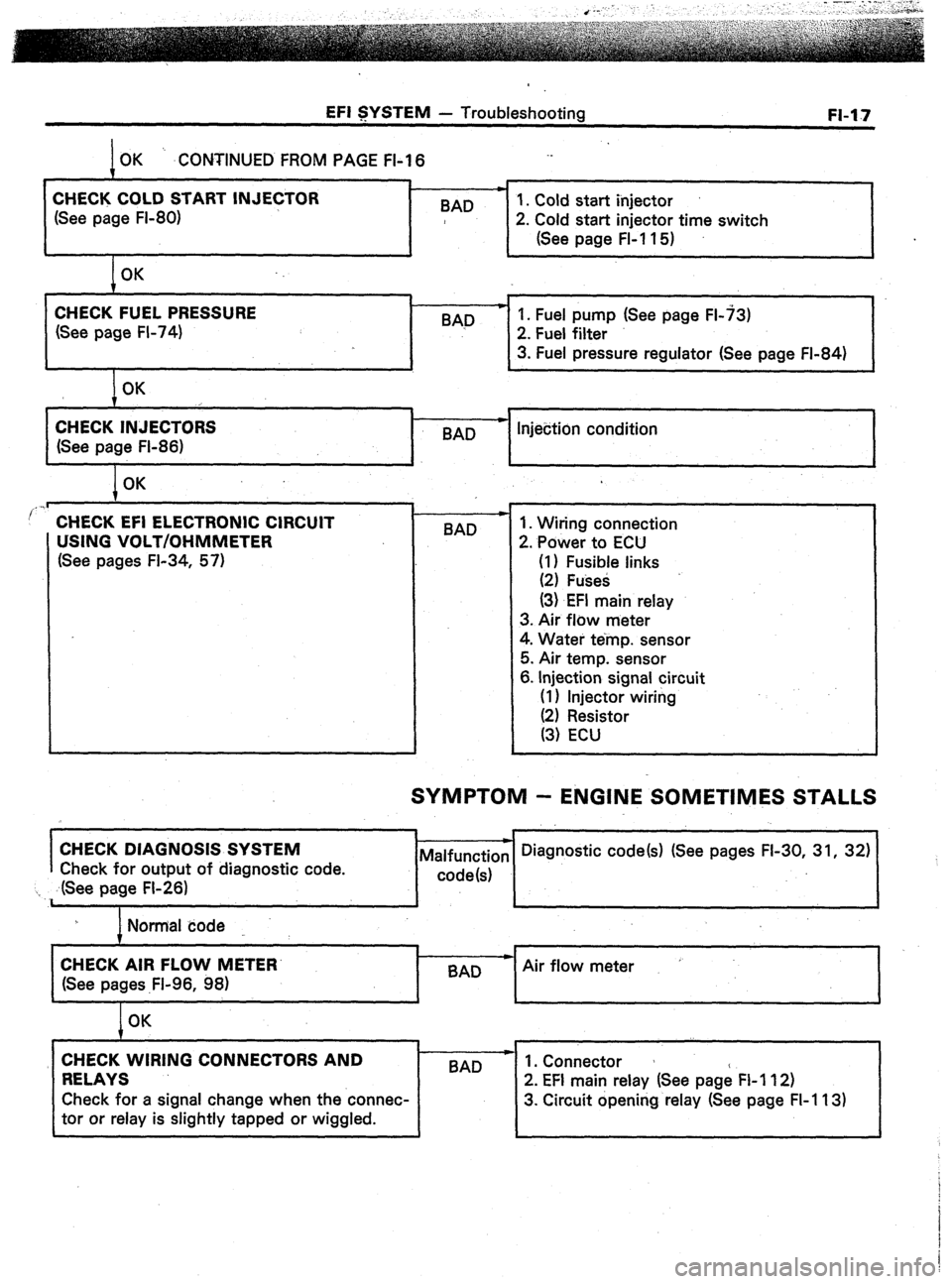
EFI SYSTEM - Troubleshooting
OK ‘. .CONTINUED FROM PAGE FI-I 6
m
CHECK COLD START INJECTOR
1. Cold start injector
(See page FI-80) BAD
2. Cold start injector time switch
(See page FL11 5)
OK FI-17
CHECK FUEL PRESSURE
(See page FI-74) BAD p 1. Fuel pump (See page FL73)
2. Fuel filter
3. Fuel pressure regulator (See page FI-84)
OK
CHECK INJECTORS
(See page FI-86) c
-
BAD Injection condition
I OK
..I
’ CHECK EFI ELECTRONIC CIRCUIT
USING VOLT/OHMMETER
(See pages FI-34, 57) BAD 1. Wiring connection
2. Power to ECU
(I) Fusible links
(2) Fuses
(3) EFI main relay
3. Air flow meter
4. Water temp. sensor
5. Air temp. sensor
6. Injection signal circuit
(I 1 Injector wiring
SYMPTOM - ENGINE SOMETIMES STALLS
I
CHECK DIAGNOSIS SYSTEM
Check for output of diagnostic code.
‘I ,. ,dSee page FI-26)
I Normal code
I
CHECK AIR FLOW METER’
Air flow meter
(See pages .Fl-96, 98)
I
OK
CHECK WIRING CONNECTORS AND
RELAYS 1 BAD --
2’ EFI main relay (See page FI 112)
Check for a signal change when the connec- 3. Circuit opening relay (See page FI-113)
tor or relay is slightly tapped or wiggled.
Page 53 of 346
EFI SYSTEM - Troubleshooting
FI-19
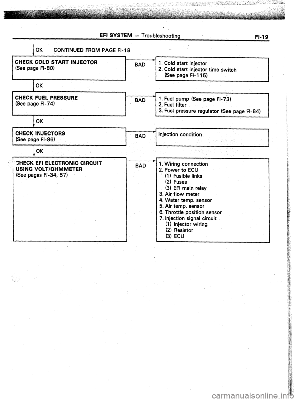
CONTINUED FROM PAGE Fl-18 ._
t
CHECK COLD START INJECTOR *
(See page FI-80) BAD 1. Cold start injector
2. Cold start injector time switch
(See page FL11 5)
CHECK FUEL PRES$URE
(See page FL74) BAD c 1. Fuel pump (See page FI-73)
2. Fuel filter
.3. Fuel pressure regulator (See page FI-84)
I
I 1 c 4
/OK
I
CHECK INJECTORS
(See page FI-86) 8AD * Injection condition
I OK
L 1
ZHECK EFI ELECTRONIC CIRCUIT
USING VOLT/OHMMETER
(See pages FL34, 57) c
BAD 1. Wiring connection
2. Power to ECU
\‘l’, F;t;e links
(3) EFI main relay
3. Air flow meter
4. Water temp. sensor
5. Air temp. sensor
6. Throttle position sensor
7. Injection signal circuit
(1) injector wiring
Page 55 of 346
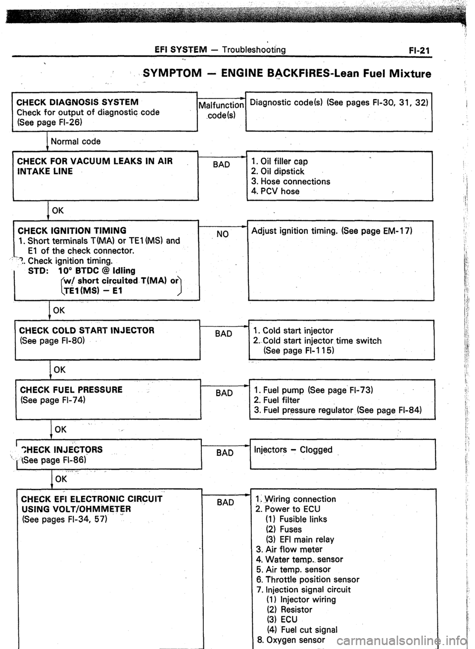
EFI SYSTEM - Troubleshooting
FI-21
-.
SYMPTOM - ENGINE BACKFtRES-Lean Fuel Mixture
CHECK DIAGNOSIS SYSTEM
Check for output of diagnostic code
(See page FI-26) Malfunction --) Diagnostic code(s) (See pages FI-30, 31, 32)
.code 1s) j
,
Normal code
CHECK FOR VACUUM LEAKS IN AIR
INTAKE LINE
1. Short terminals T(MA) or TEl (MS) and BAD -
NO 1. Oil filler cap
2. Oil dipstick
3. Hose connections
4. PCV hose
Adjust ignition timing. (See page EM-1 7)
1. Cold start injector
2. Cold start injector time switch
(See page FI-115)
CHECK FUEL PRESSURE
(See page FI-74)
I
I
BAD 1. Fuel pump (See page‘ FI-73)
2. Fuel filter
3. Fuel pressure regulator (See page Fl-84)
I
’ “,HECK INJib
‘I- See page FI-86)’ - Injectors - Clogged
BAD
. ., .l
I OK
CHECK Eii ELECTRONIC ClR&lT
USING VOLT/OHMMETER
(See pages FI-34, 57)
4
BAD 1. Wiring connection
2. Power to ECU
(1) Fusible links
(2) Fuses
(3) EFI main relay
3. Air flow meter
4. Water temp. sensor
5. Air temp. sensor
6. Throttle position sensor
7. Injection signal circuit
(1) Injector wiring
Ii, zesstor
(4) Fuel cut signal
8. Oxygen sensor
Page 57 of 346
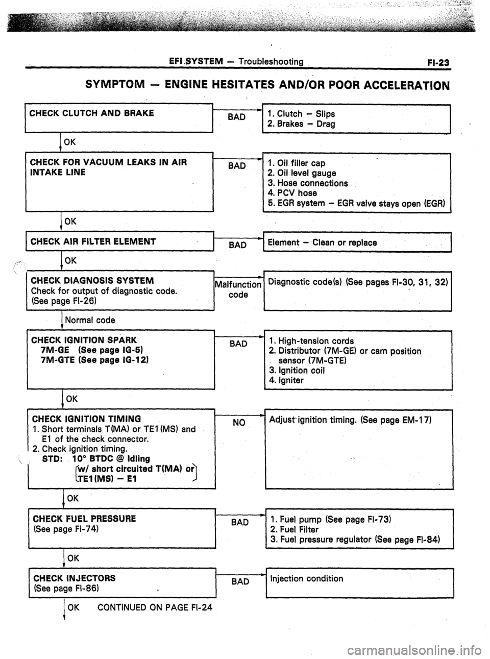
EFI SYSTEM - Troubleshooting
FI-23
SYMPTOM - ENGINE HESITATES AND/OR POOR ACCELERATION
CHECK CLUTCH AND BRAKE .
BAD
I
I 1
1 OK
CHECK FOR VACUUM LEAKS IN AIR
INTAKE LINE
I OK BAD
I-
1. Clutch - Slips
2. Brakes - Drag
1. Oil filler cap
2. Oil level gauge
3. Hose connections :
4. PCV hose
5. EGR system - EGR valve stays open (EGR)
4
CHECK AIR FILTER ELEMENT
BAD Element - Clean or replace
I
,,: -. OK
7
. . 1 i , 1
CHECK DIAGNOSIS SYSTEM
Check for output of diagnostic code.
(See page FI-26) Malfunction
I-- code Diagnostic code(s) (See pages FI-30, 31, 32)
I
I I I J
1 Normal code
CHECK IGNITION SPARK
7M-GE (See page IO-61
7M-GTE (See page 16-12) .
BAD
I
I OK
CHECK IGNITION TIMING
1. Short terminals T(MA1 or TEl (MS) and
El of the check connector.
2. Check ignition timing.
‘i, STD: 10” BTDC @ Idling
I short circuited TiMA) or
I
I OK
CHECK FUEL PRESSURE
(See page Fl-74) 1. High-tension cords
2. Distributor (7M-GE) or cam position
sensor (7M-GTE)
3. Ignition coil
4. Igniter
NO Adjust. ignition timing. (See page EM- 17)
I
I
BAD
I
1. Fuel pump (See page Fl-73)
2. Fuel Filter
3. Fuel pressure regulator (See page Fl-84)
1
OK
CHECK INJECTORS
(See page FI-86) BAD c Injection condition
OK CONTINUED ON PAGE FI-24
Page 107 of 346
EFI SYSTEM - Fuel System FI-73
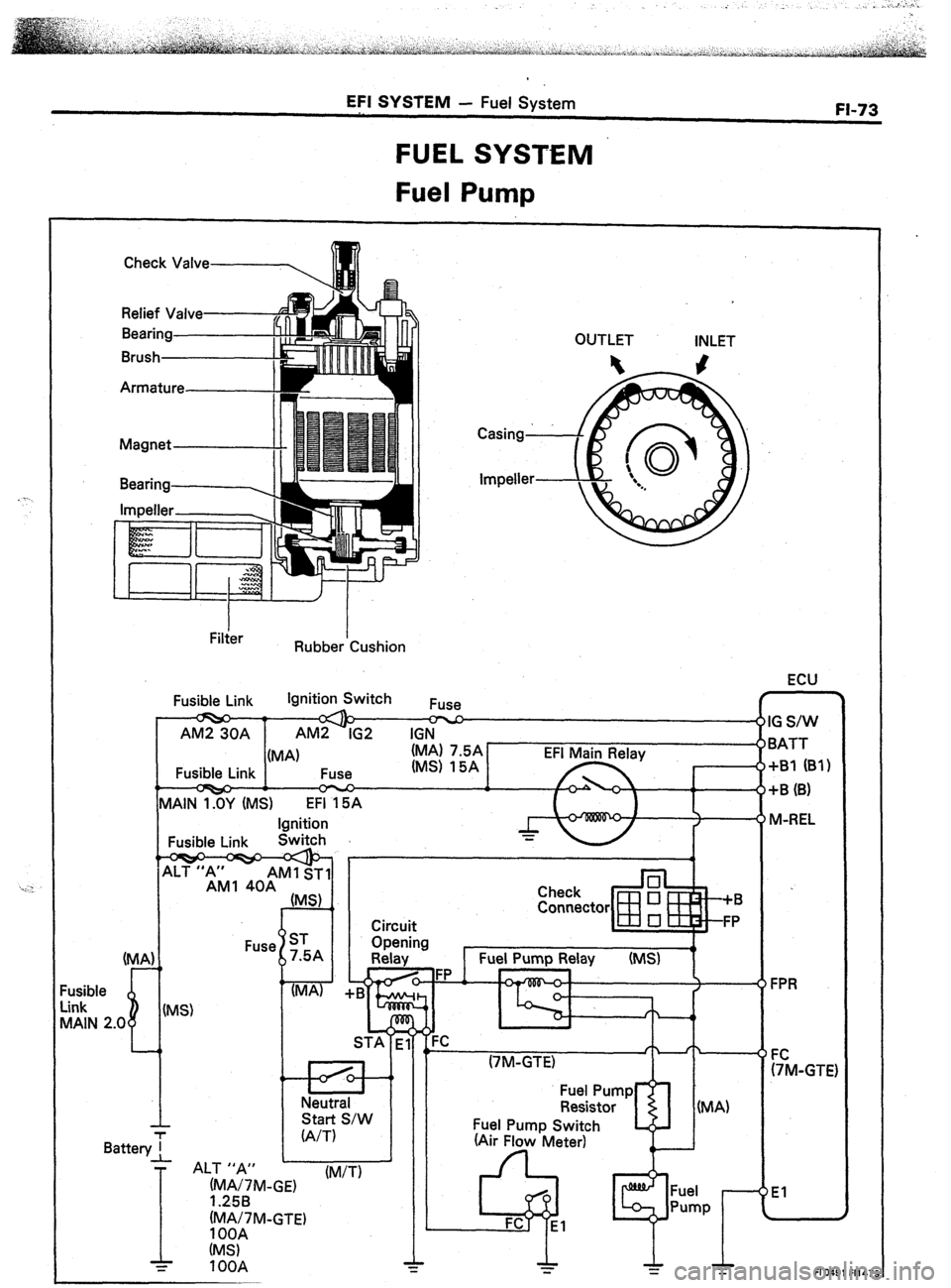
FUEL SYSTEM
Fuel Pump
Check Valve-------,
n!
Relief Valved
Bearing
Brush OUTLET INLET
Armature
I Filter I
Rubber Cushion
ECU
Fusible Link Ignition Switch
1 G S/W
3ATT
tB1 (B’l
I-B (B)
WREL
FPR
9’
FM-CT
El 1 AM2 30A 1 AM2-IG2 IGN
(MA)
Fusible Link Fuse
‘Q-p
I EFI Main Relay
fc4 r
MAIN I%? (MS) EFi 15A
Ignition
Fusible Link Switch 1
‘El
I
m AM1 ST1
AM1 40A
” (MA)
(MS) Check
Connector
Circuit
usible
ink
IAIN 2.0
I
F
L
(Air Flow Meter) (MA)
Battery1
T
ALT ,,A#, w
(M/T)
1
(MA/7M-GTE)
1 OOA
(MS)
= 1 OOA
FlO491 Fl14