Page 9 of 346

CH-2 CHARGING SY&EM - Precautions, Troubleshooting
._
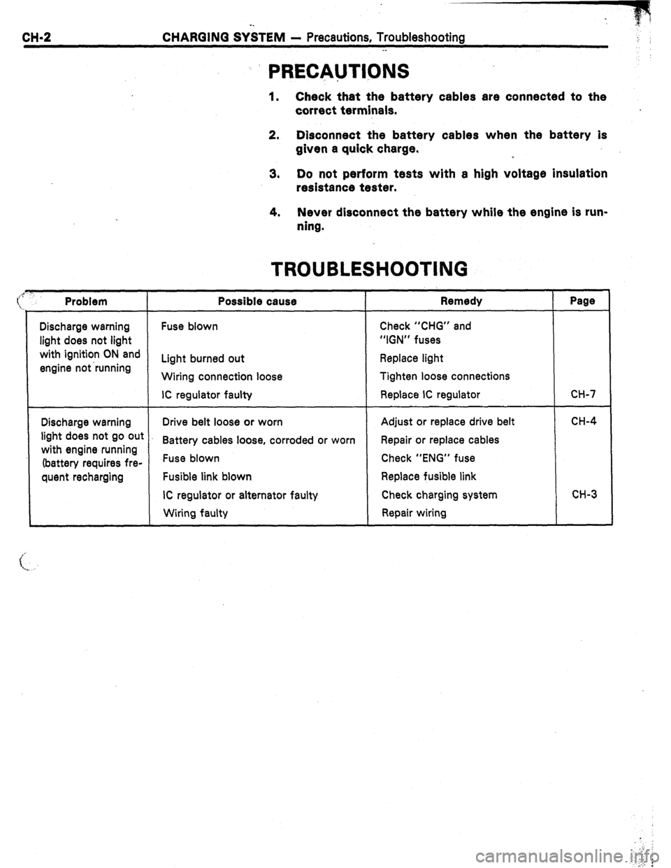
: PRECAUTIONS
1. Check that the battery cables are connected to the
correct terminals.
2. Disconnect the battery cables when the battery is
given a quick charge.
3. Do not perform tests with a high voltage insulation
resistance tester.
4. Never disconnect the battery while the engine is run-
ning.
Discharge warning
light does not light
with ignition ON and
engine not ‘running
Problem
Discharge warning
light does not go out
with engine running
(battery requires fre-
quent recharging
Possible cause
Fuse blown
Light burned out
Wiring connection loose
IC regulator faulty
TROUBLESHOOTING
Remedy
Check “CHG” and
“IGN” fuses
Replace light
Tighten loose connections
Replace IC regulator
Drive belt loose or worn
Battery cables loose, corroded or worn
Fuse blown
Fusible link blown
IC regulator or alternator faulty
Wiring faulty Adjust or replace drive belt
Repair or replace cables
Check “ENG” fuse
Replace fusible link
Check charging system
Repair wiring
Page
CH-7
CH-4
CH-3
Page 47 of 346
EFI SYSTEM - Troubleshdoting
FI-13
. .
Digital Type
Analog Type 4. Use a volt/ohmmeter .with high impedance (10 k.RN
minimum) for troubleshooting of the electrical circuit.
(See pages FL34, 57)
TROUBLESHOOTING PROCEDURES
SYMPTOM - DIFFICULT TO START OR NO START
(EbIJiiIf)l& WILL NO? CRANK OR CRANK$ SLOWLY)
w
CHECK ELECTRIC SOURCE
BAD 1. Battery
.-
(1) Connection
(2) Gravity - Drive belt - charging system
(3) Voltage
2. Fusible links
OK
CHECK STARTING SYSTEM c
BAD 1. Ignition switch
2. Starter relay (MS)
3. Starter
4. Neutral start switch (A/T)
5. Wiring/Connection
Page 331 of 346

Air
Cleaner
i
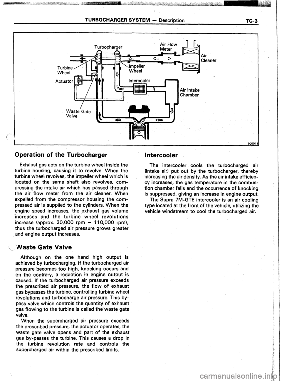
Operation of the Turbocharger
Waste’Gate
Valve Intercooler
Air intake
Chamber
Exhaust gas.acts on the turbine wheel inside the
turbine housing, causing it to revolve. When the
turbine wheel revolves, the impeller wheel which is
located on the same shaft also revolves, com-
pressing the intake air which has passed through
the air flow meter from the air cleaner. When
expelled from the compressor housing the com-
pressed air is supplied to the cylinders. When the
engine speed increases, the exhaust gas volume
increases and the turbine wheel revolutions
increase (approx. 20,000 rpm - 110,000 rpm),
thus the turbocharged air pressure grows greater
and engine output increases.
I, Waste Gate Valve
Although on the one hand high output is
achieved by turbocharging, if the turbocharged air
pressure becomes too high, knocking occurs and
on the contrary, a reduction in engine output is
caused. If the turbocharged air pressure exceeds
the prescribed air pressure, the flow of exhaust
gas bypasses the turbine, controlling turbine wheel
revolutions and turbocharge air pressure. This by-
pass valve which controls the quantity of exhaust
gas flowing to the turbine is called the waste gate
valve.
When the supercharged air pressure exceeds
the prescribed pressure, the actuator operates, the
waste gate valve opens and part of the exhaust
gas by-passes the turbine. This causes a drop in
the turbine revolution rate and controls the
supercharged air within the prescribed limits.
Intercooler
The intercooler cools the turbocharged air
(intake air) put out by the turbocharger, thereby
increasing the air density. As the air intake efficien-
cy increases, the gas temperature in the combus-
tion chamber falls and the occurrence of knocking
is suppressed, giving an increase in engine output.
The Supra 7M-GTE intercooler is an air cooling
type located at the front of the vehicle, utilizing the
vehicle windstream to cool the turbocharged air.
Page 333 of 346

TURBOCHARGER SYSTEM - Troubleshooting TC-5
TROUBLESHdOTlNG
NOTE: Before troubleshooting the turbocharger, first
check the engine itself. (Valve clearance, engine compres-
sion, ignition timing etc.)
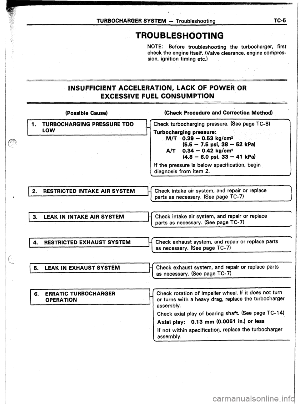
INSUFFICIENT ACCELERATION, LACK OF POWEk OR
EXCESSIVE FUEL CONSUMPTION
(Possible Cause)
I
1. TURBOCHARGING PRESSURE TOO
LOW
t
’ (Check Procedure and Correction Method)
Check turbocharging pressure. (See page TC-8)
Turbocharging pressure:
M/T 0.39 - 0.53 kg/cm2
(5.5 - 7.5 psi, 38 - S2 kPa)
A/T 0.34 - 0.42 kg/cm2
(4.8 - 6.0 psi, 33 - 41 kPa)
If the pressure is below specification, begin
diagnosis from item 2.
2. RESTRICTED INTAKE AIR SYSTEM Check intake air system, and repair or replace
‘1
parts as necessary. (See page TC-7)
J
.
3. LEAK IN INTAKE AIR Check intake air system, and repair or replace
parts as necessary. (See page TC-7)
.
4. RESTRICTED EXHAUST SYSTEM Check exhaust system, and repair or replace parts
as necessary. (See page TC-7)
Check exhaust system, and repair or replace parts
as necessary. (See page TC-7)
6. ERRATIC TURBOCHARGER
OPERATION Check rotation of impeller wheel. If it does not turn
or turns with a heavy drag, replace the turbocharger
assembly.
Check axial play of bearing shaft. (See page TC- 14)
Axial play: 0.13 mm (0.0051 in.) or less
If not within specification, replace the turbocharger
assembly.
Page 336 of 346

TC;8 TUWOCHARGER SYSTEM--- Turbocharger
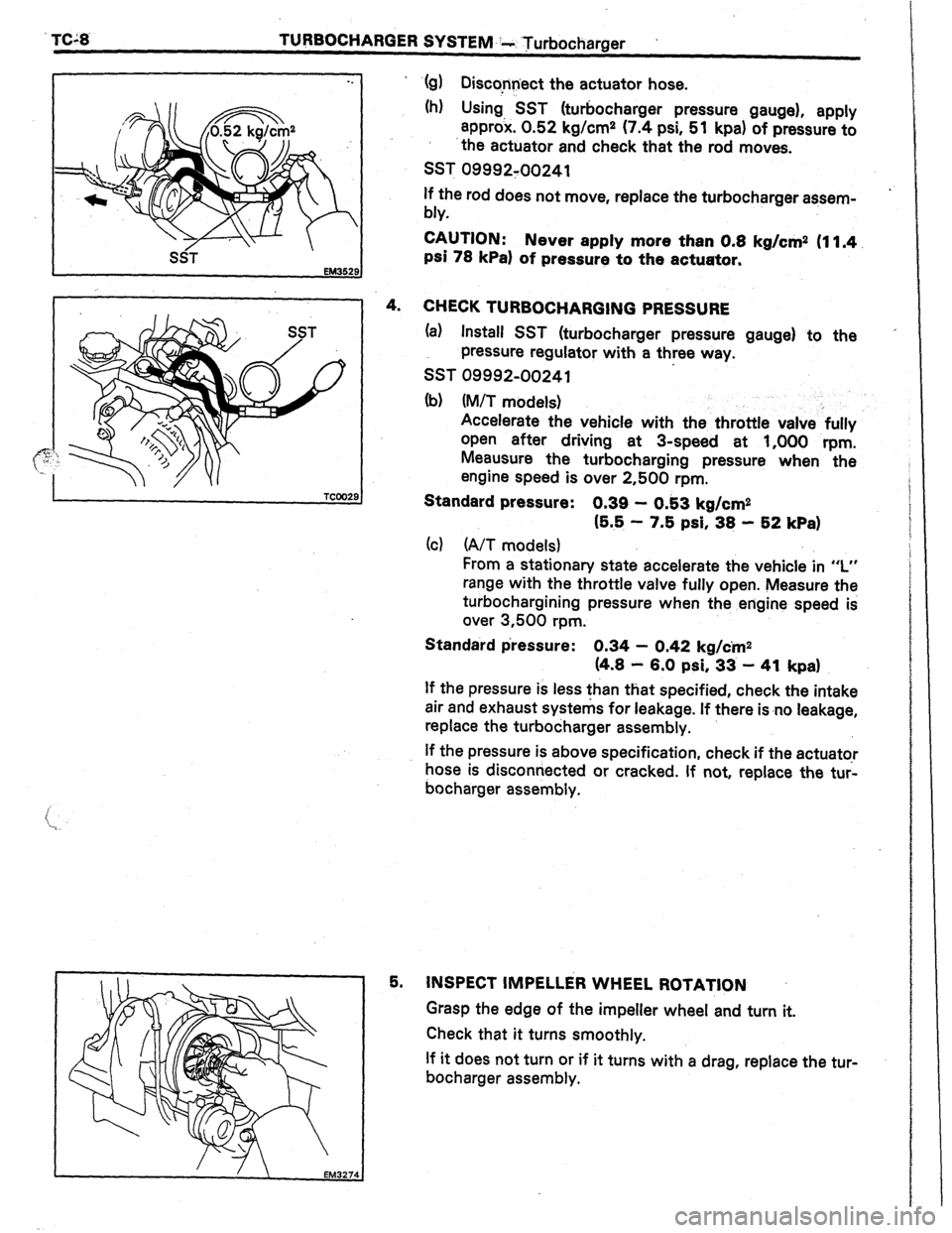
-. ‘(g) Disccnnect the actuator hose.
(h) Using, SST (turbocharger pressure gauge), apply
approx. 0.52 kg/cm2 (7.4 psi, 51 kpa) of pressure to
‘the actuator and check that the rod moves.
SST 09992:00241
SST
EM352!
If the rod does not move, replace the turbocharger aasem-
bly.
CAUTION: Never apply more than 0.8 kg/cm2 (11.4.
psi 78 kPa1 of pressure to the actuator.
4.
CHECK TURBOCHARGING PRESSURE
(a) Install SST (turbocharger pressure gauge) to the
pressure regulator with a three way.
SST 09992-00241
(b) (M/T models)
Accelerate the vehicle with the throttle valve fully
open after driving at 3-speed at 1,000 rpm.
Meausure the turbocharging pressure when the
engine speed is over 2,500 rpm.
Standard pressure:
0.39 - 0.53 kg/cm2
(6.8 - 7.8 psi, 38 - 82 kPa)
(c) (A/T models)
From a stationary state accelerate the vehicle in I”
range with the throttle valve fully open. Measure the
turbochargining pressure when the engine speed is
over 3,500 rpm.
Standard p‘ressure: 0.34 - 0.42 kg/em2
(4.8 - 8.0 psi, 33 - 41 kpa)
If the pressure is less than that specified, check the intake
air and exhaust systems for leakage. If there isno leakage,
replace the turbocharger assembly.
If the pressure is above specification, check if the actuator
hose is disconnected or cracked. If not, replace the turl
bocharger assembly.
I l,Il - 1 5, INSPECT IMPELLiR WHEEL ROTATION
/-L
EM32
Grasp the edge of the impeller wheel and turn it.
Check that it turns smoothly.
If it does not turn or if it turns with a drag, replace the tur
bocharger assembly.
1 :74