Page 22 of 346
. .
co-2 COOLING SYSTEM - Description
,- I . . .
DESCRlqTlON
This engine utilizes a pressurized water forced circulation cooling system which includes a thermostat equip-
ped mounted on the outlet side.
5 7M-GE
Throttle Body
ISC Valve
/
To Radiator
RHD
/
From Heater
rM-GTE
/
To Heater From Heat: ISC Valve
To Radiator
COGS
COOF
Page 35 of 346

FI-1
i’.. ;
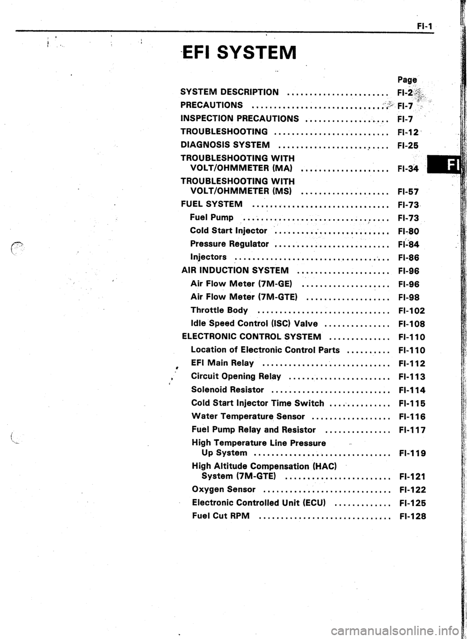
-EFI SYSTEM
i
‘x
. .
Page
SYSTEM DESCRIPTION
....................... Fl-i.&.
PRECAUTIONS
;;:“, F,-, ;a”“- .............................. . ....
INSPECTION PRECAUTIONS
FI-7 . ....................
TROUBLESHOOTING
.......................... FI-12
DIAGNOSIS SYSTEM
.................... .
.... FI-25
TROUBLESHOOTING WITH
VOLT/OHMMETER (MA)
.................... FI-34
m
.:
TROUBLESHOOTING WITH
VOLT/OHMMETER (MS)
.................... FI-57
FUEL SYSTEM
................................ FI-73,
Fuel Pump ..................................
FI-73
Cold Start Injector ...........................
Fl-80
Pressure Regulator
.......................... FI’i84 ..
Injectors
.............................. ..i ..
FI-86
AIR INDUCTION SYSTEM
..................... FI-96
Air Flow Meter (7M-GE)
..................... FI-96
Air Flow Meter (7M-GTE)
................... FI-98
Throttle Body
.............................. FI-102
Idle Speed Control (ISC) Valve
............... FI-108
ELECTRONIC CONTROL SYSTEM .............. FI-110
Location of Electronic Control Parts .......... FI-110
l EFI Main Relay
............................. Fl-112
. Circuit Opening Relay ....................... FI-113
Solenoid Resistor
........................... Fl-114
Cold Start Injector Time Switch ...............
FI-115
Water Temperature Sensor ..................
FI-116
Fuel Pump Relay and Resistor ............... FI-117
High Temperature Line Pressure -
Up System ............................... FIi119
High Altitude Compensation (HACK
System (7M-GTE)
........................ FI-121
Oxygen Sensor .............................
FI-122
Electronic Controlled Unit (ECU) .............
FI-125
Fuel Cut RPM
.............................. FI-128
Page 54 of 346

.20 EFI SYSTEM - Troubleshooting __
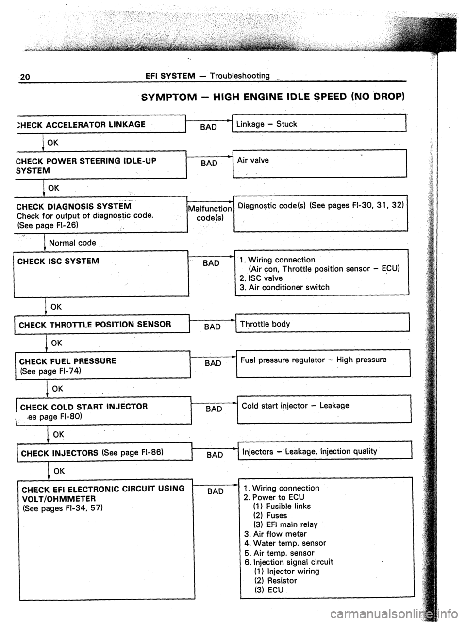
SYMPTOM - HIGH ENGINE IDLE SPEED (NO DROP)
:HECK ACCELERA
OK
CHECK POWER STEERING !DLE+JP
SYSTEM
OK .
‘:
j..l.
CHECK DIAGNOSIS SYSTEM
Check for output of diagnostic code.
(See page FI-26) ‘:.
_T I Linkage - Stuck
I
9
BAD * Air valve
I
r
* Diagnostic code(s) (See pages FI-30, 31, 32)
Malfunction
..
code!s)
Normal code
.
CHECK ISC SYSTEM
BAD
I
OK
71
(Air con Throttle posrtron sensor - ECU)
1 CHECK THROTTLE POSITION SENSOR
t-x- Throttle body
OK
CHECK FUEL PRESSURE
(See page FI-74) 7
BAD w Fuel pressure regulator - High pressure
OK
CHECK COLD START INJECTOR
~ .ee page FI-80) BAD w Cold start injector - Leakage
CHECK INJECTORS (See page FI-86)
I Injectors - Leakage, Injection quality
I OK
CHECK EFI ELECTRONIC CIRCUIT USING
VOLT/OHMMETER
(See pages FI-34, 57) BAD - 1. Wiring connection
2. Power to ECU
(1) Fusible links
(2) Fuses
(3) EFI main relay
3. Air flow meter
4. Water temp. sensor
5. Air temp. sensor
6. Injection signal circuit
(1) Injector wiring
(2) Resistor
(3) ECU
Page 72 of 346

EFI SYSTEM - Troubleshooting with Volt/Ohmmeter (MA)
. .
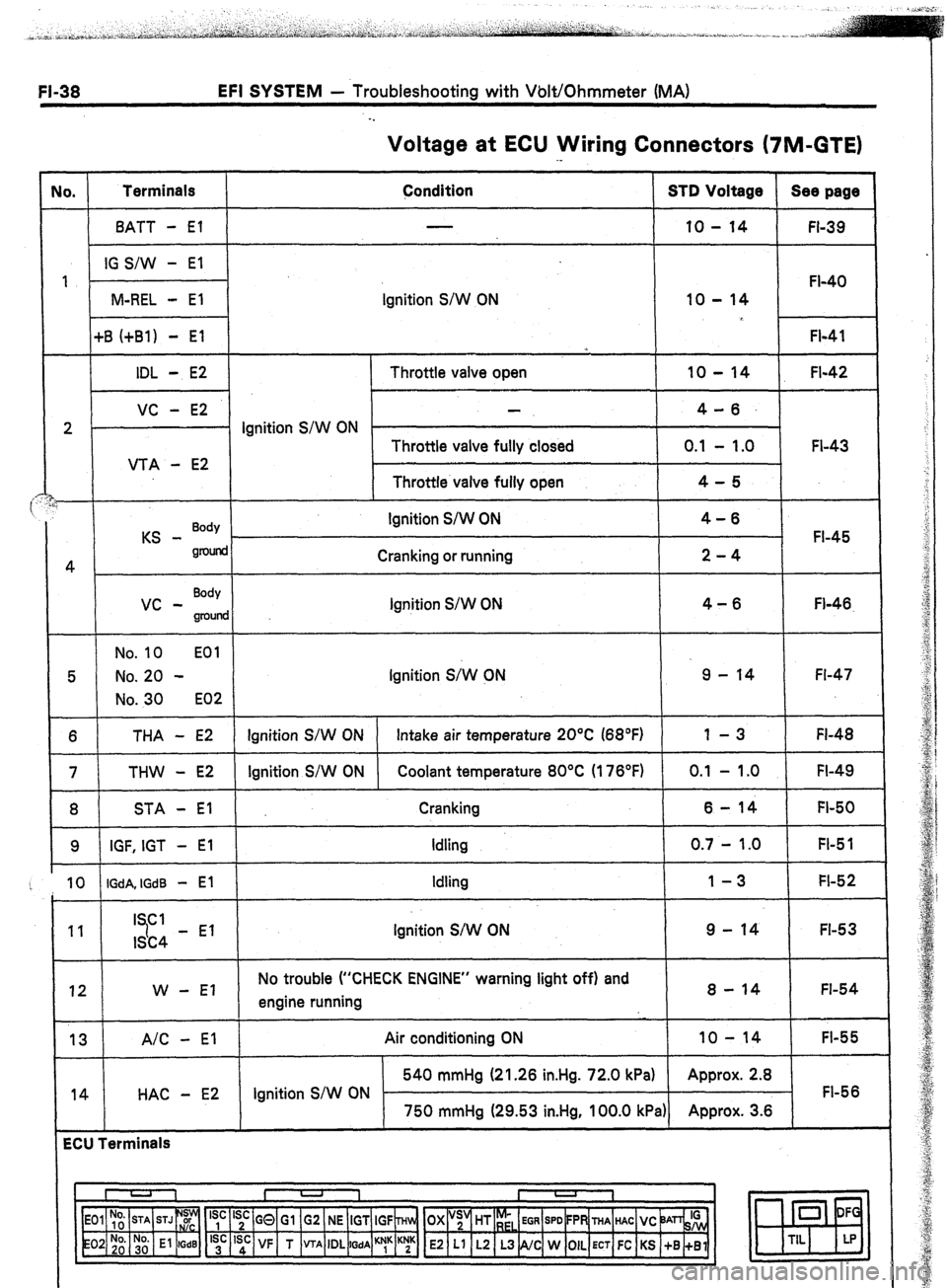
Voltage at ECU Wiring Connectors (7M-GTE)
No. Terminals
Condition STD Voltage Sea page
BATT - El 10 - 14
FI-39
IG S/W - El
1
FI-40
M-REL - El Ignition S/W ON 10 - 14
+B (+Bl) - El
FI-41
*
IDL - E2 Throttle valve open 10 - 14 FI-42
VC - E2 4-6.
2 . Ignition S/W ON
Throttle valve fully closed 0.1 - 1.0 FI-43
VTA - E2
Throttle valve fully open 4-5
i
KS - Body Ignition S/W ON 4-6
FI-45
gnMid
4 Cranking or running 2-4
vc - Body
Ignition S/W ON 4-6
groulld Fl-46.
No. 10 EOl
5 No. 20 - Ignition S;W CN 9 - 14 Fl-47
No. 30 E02
6 THA - E2 Ignition S/W ON Intake air temperature 20°C (68°F) 1 -3 FI-48
7 THW - E2 Ignition S/W ON Coolant temperature 80°C (176°F) 0.1 - 1 .O FI-49
8 STA - El Cranking 6-14 FI-50
9 IGF, IGT - El Idling 0.7 - 1.0 FI-5 1
10 IGdA, IGdB - El Idling 1-3 FI-52
11 I Cl
7 9 - 14 FI-53
ISC4 - El Ignition S/W ON
12 W - El No trouble (“CHECK ENGINE” warning light off) and
engine running 8 - 14 FI-54
13 A/C - El
14 HAC - E2 Air conditioning ON 10 - 14
FI-55
540 mmHg (21.26 in.Hg. 72.0 kPa) Approx. 2.8
Ignition S/W ON FI-56
750 mmHg (29.53 in.Hg, 100.0 kPa) Approx. 3.6
ECU Terminals
I U 1 I -
I
1
‘yc ‘;c GQ Gl G2 NE IGT IGF ~Hln, OX “;’ HT r;,
EGR SPD FPR THA HAC VC ‘JAn& 0 DF
‘;’ ‘sd: VF T VTA IDL
WA ““1” K;K E2 Ll L2 L3 NC W OIL ECT FC KS +B +Bl m
TIL LP
Page 76 of 346
;I-42 EFI SYSTEM - Troubleshooting with Volt/Ohmmeter (MA)
NO, Terminals
IDL - E2 Trouble Condition ..
Throttle valve open STD Voltage
10 - 14 v
2 }-I No voltage / s$t;;N -
Throttle valve fully closed o.‘: I;,; v
I VTA - E2
I I Throttle valve fully c
I I I I
Throttle Position Sensor
Ei
I IDL
VTA
VC
El 4-5v
I
Voltmeter
R102,
FlO31
l IDL - E2
0 There is no voltage between ECU terminals IDL and E2.
(IO S/W ON) (Throttle valve open)
c
I
0 Check that there is voltage between ECU terminal +B (+Bl)
and body ground. (IO S/W ON)
c h
, 1
1 OK ’
1 1 Check wiring between ECU terminal El and body ground.1
t
Refer to No. 1.
(See page FI-41)
I
BAD
7
- Replace or repair.
1
b
OK
,
1
I@ Check throttle position sensor. 1 BAD
1
I BAD OK
.
Check wiring between ECU and
throttle position sensor.
1
Page 77 of 346
EFI SYSTEM - Troubleshooting with Volt/Ohmmeter (MA) FI-43
Voltmeter
El v:
(r:
c
cc
I ECU A VTA
Fll62f
Voltmeter
m ECU vc
l VC - E2
0 There is no voltage between ECU terminals VC and E2.
(IO
S/W ON)
1
Check that there is voltage between ECU terminal +6 (+El) and
body ground. (IO S/W ON)
OK
CD Check throttle position sensor,
(See page FI-102)
BAD
OK
I
I Repair or replace.
I 1 Check wiring between ECU and throttle
nosition sensor. I
I I I’
I I
1 OK
1 BAD
1 1
I I T
I
I Try another ECU. 1 :;;i. or replace 1
. VTA - E2
@There is no specified voltage at ECU terminals VTA and E2.
(IG S/W ON)
1
0
Check that there is voltage between ECU terminal VC and E2.
(IO S/W ON)
1 OK
t 1
7 I I
I
Check wiring between ECU and
BAD
throttle position sensor.
H Repair or replace.
I
1
J I I
I OK
I Try another ECU.
Page 97 of 346
EFI SYSTEM - Troubleshooting with Volt/Ohmmeter (MS)
FI-63
No. 1 Terminals 1 Trouble 1
Condition S-m Vnlttlnq --- ‘-‘-P-~
IDL
- E2 Throttle valve open
10 - 14 v
vcc - E2
2
No voltage Ignition 4-6V
switch ON
VTA - E2 Throttle valve fully closed 0.1 - l.OV
Throttle valve fully open
4-!iv
ECU .s
r
Fl136
I . IDL - E2
ECU
I ECU
I Y ,
F12767
0 There is no voltage between ECU terminals IDL and E2.
(IO S/W ON) (Throttle valve open)
I
1
0 Check that there is voltage between ECU terminal B (Bl) and
body ground.
(IO S/W ON)
NO
OK
, 1
I I Check wiring between ECU terminal El and body
I
1 ground.
OK
Try another ECU. 1
BAD
I Repair or replace.
I i
t
Refer to No. 1. BAD
(See page FI-62) p Replace or repair.
t
OK
, t
I@ Check throttle position sensor, ]
BAD
BAD
OK
*
Replace or repair Check wiring between ECU and
throttle position sensor. throttle position sensor.
1
OK
Try another ECU.
‘!
t
Page 98 of 346
FI-64 EFI SYSTEM - Troubleshooting with Volt/Ohmmeter (MS)
Fl162
. VCC - E2 .
0
There is no voltage between ECU terminals VCC and E2.
(IO S/W ON)
1
I
Check that there is voltage between ECU terminal B (Bl) and
body ground. II0 S/W ON1
OK
7
0 Check throttle position sensor. Refer to No. 1.
(See page FL102)
(See page FL62)
k
I OK
,
1 Repair or replace.‘ / Check wiring between ECU and throttle position sensor.
OK
t I , 1 BAD ,
1 Rwe;ix3;.or replace ]
Try another ECU.
l VTA - E2
I- I
0 There is no specified voltage at ECU terminals VTA and E2.
(IG S/W ON)
I
0 Check that there is voltage between ECU terminal VCC and E2.
(IO S/W ON)
I 1
I OK
I
[@ Check thrc1 BAD 4 Repair or replace. 1
I
1 OK I ‘1 4 Check wiring between ECU and
throttle position sensor.
I
1 OK BAD
- Repair or replace.
1 Try another ECU.
1
I