1987 TOYOTA CELICA air condition
[x] Cancel search: air conditionPage 25 of 346
COOLING SYSTEM i Check and Replacement of Engine Coolant
co-5
._
CHECK AND REPLACEMENT OF
ENGINE COOLANT
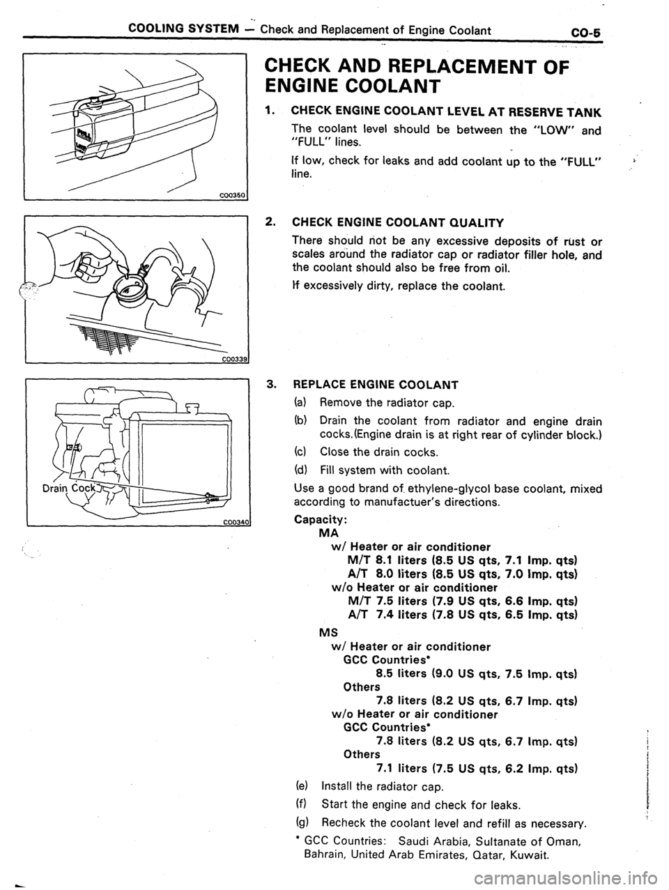
1. CHECK ENGINE COOLANT LEVEL AT RESERVE TANK
The coolant level should be between the “LOW” and
“FULL” lines.
If low, check for leaks and add coolant up to the “FULL”
line. .,>‘
2. CHECK ENGINE COOLANT QUALITY
There should not be any excessive deposits of rust or
scales around the radiator cap or radiator filler hole, and
the coolant should also be free from oil.
lf excessively dirty, replace the coolant.
3. REPLACE ENGINE COOLANT
(a) Remove the radiator cap.
(b) Drain the coolant from radiator and engine drain
cocks.(Engine drain is at right rear of cylinder block.)
(cl Close the drain cocks.
(d) Fill system with coolant.
Use a good brand of. ethylene-glycol base coolant, mixed
according to manufactuer’s directions.
Capacity:
MA
w/ Heater or air conditioner
M/T 8.1 liters (8.5 US qts. 7.1 Imp. qts)
A/T 8.0 liters (8.5 US qts, 7.0 Imp. qts)
w/o Heater or air conditioner
M/T 7.5 liters (7.9 US qts, 6.6
Imp. qts)
A/T 7.4 liters (7.8 US qts, 6.5 Imp. qts)
MS
w/ Heater or air conditioner
GCC Countries*
8.5 liters (9.0 US qts, 7.5 Imp. qts)
Others
7.8 liters (8.2 US qts, 6.7 Imp. qts)
w/o Heater or air conditioner
GCC Countries*
7.8 liters (8.2 US qts, 6.7 Imp. qts)
Others
7.1 liters (7.5 US qts, 6.2 Imp. qts)
(e) Install the radiator cap.
(f) Start the engine and check for leaks.
(g) Recheck the coolant level and refill as necessary.
l GCC Countries: Saudi Arabia, Sultanate of Oman,
Bahrain, United Arab Emirates, Qatar, Kuwait.
Page 40 of 346
1-6 EFI SYSTEM - System Description
‘he .EFI system is composed of 3 basic sub
;ystems; Fuel Induction, Air Induction and
Ziectronic Control.
FUEL SYSTEM
An electric fuel pump supplies sufficient fuel,
under a constant pressure, to the injectors. These
injectors inject a metered quantity of fuel into the
intake manifold in accordance with signals from
the ECU (Electronic Control Unit).
AIR INDUCTION SYSTEM
The air induction system provides sufficient air for
engine operation.
[3: ‘I
i&TRONIC CONTROL SYSTEM
The 7M-GE, 7M-GTE engines are equipped wifh a
Toyota Computer Control System (TCCS) which
centrally controls the EFI, ESA, Diagnosis systems,
etc. by means of an Electronic Control Unit (ECU -
for-merly EFI computer) employing a microcom-
puter.
By means of the ECU, the TCCS controls the
following functions:
1. Electronic Fuel injection (EFI)
The ECU receivers signals from,various sen-
sors indicating changing engine operating
conditions such as:
Exhaust oxygen content (w/ TWC)
Intake air volume
i Intake air temperature
Coolant temperature
Engine rpm
Vehicle speed
Acceleration/deceleration etc.
These signals are utilized by the ECU to
determine the injection duration necessary for
an optimum air-fuel ratio.
2. Electronic Spark Advance (ESA)
The ECU is programmed with data for
optimum ignition timing under any and all
operating conditions. Using data provided by
sensors which monitor various engine func-
tions (rpm, A/C signal, coolant temperature,
etc.), the microcomputer (ECU) triggers the
spark at precisely the right instant. (See IG
section) 3. Idle Speed Control (IX)
The ECU is programmed with, target idling
speed values to respond to different engine
conditions (coolant temperature, air condi-
tioner on/off, etc.). Sensors transmit signals
to the ECU which control the flow of air
through the bypass of the throttle valve and
adjust idle speed to the target value.
(See pages FI-53, 7 1, 108) ’
4. Diagnosis
The ECU detects any malfunctions or abnor-
malities in the sensor network and tights the
“CHECK ENGINE” warning light on the instru-
ment panel. At the same time, the trouble is
identified and a diagnostic code is recorded
by the ECU.
5. Fail-Safe Function ’
In the event of computer malfunction, a back-
up circuit will take over to provide minimal
drivability. Simultaneously, the “CHECK
ENGINE” warning light will come on.
Page 46 of 346
1-12 EFI SYSTEM - Troubleshooting’
FlO48
TROUBLESH~~TI~~G
. .
TROUBLESHOOTING HlhJTS
1. Engine troubles are usually not caused by the EFI system.
When troubleshooting, always first check the condition of
the other systems.
(a) Electronic source
0 Battery
0 Fusible links
0 Fuses
(b) Body ground
(cl Fuel supply
0 Fuel leakage
0 Fuel filter
0 Fuel pump
(d) Ignition system
0 Spark plug
0 High-tension cord
l Distributor (7M-GE) or cam position sensor (7M-
GTE)
0 Igniter and ignition coil
(e) Air induction system
0 Vacuum leaks
(f) Emission control system
0 PCV system
0 EGR system (w/ EGR)
(g) Others
l Ignition timing (ESA system)
0 Idle speed (ISC system)
-r
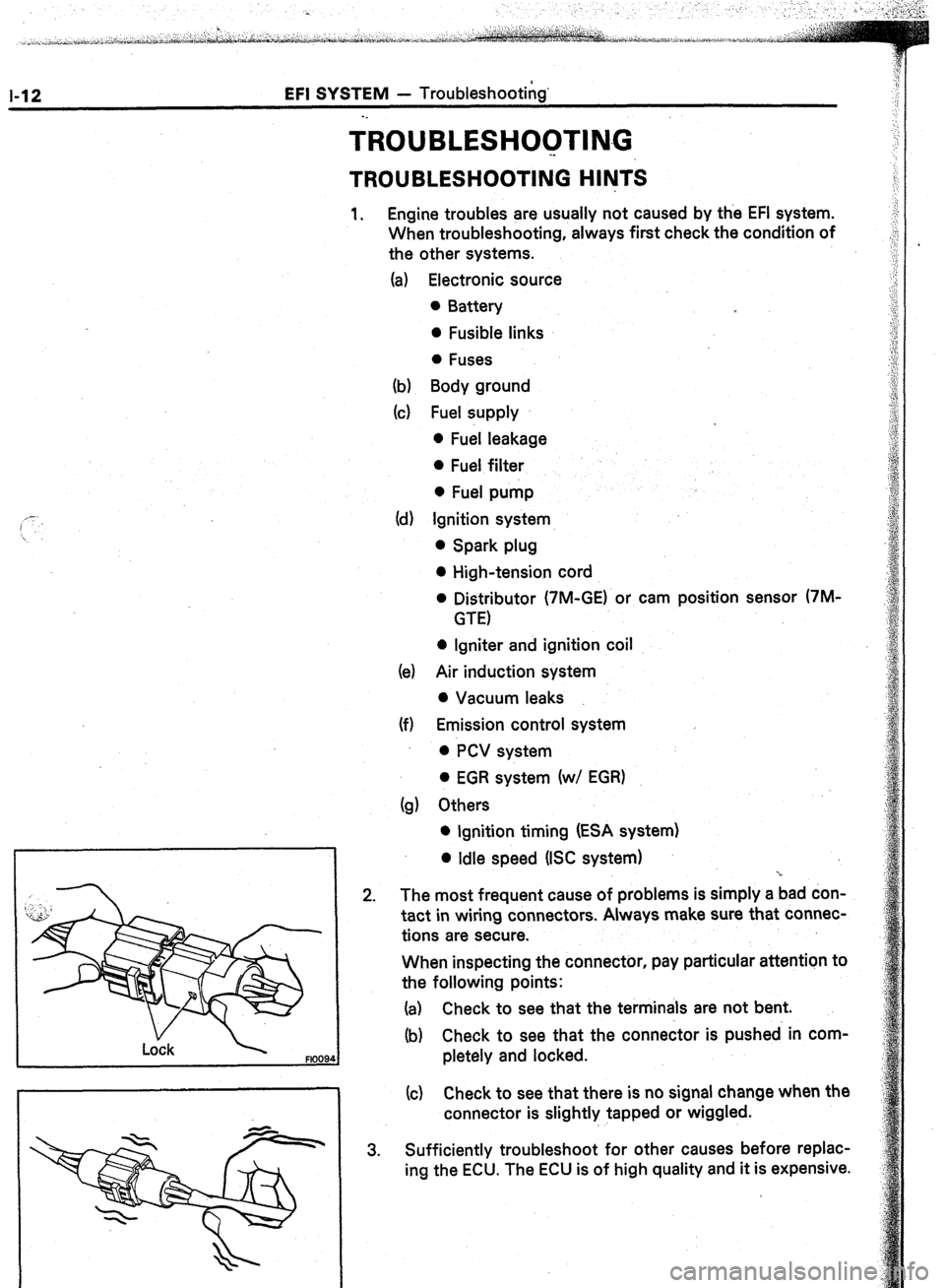
2. The most frequent cause of problems is simply a bad don-
tact in wiring connectors. Always make sure that connec-
tions are secure.
When inspecting the connector, pay particular attention to
the following points:
(a) Check to see that the terminals are not bent.
(b) Check to see that the connector is pushed in com-
pletely and locked.
(c) Check to see that there is no signal change when the
connector is slightly tapped or wiggled.
3. Sufficiently troubleshoot for other causes before replac-
ing the ECU. The ECU is of high quality and it is expensive.
Page 51 of 346
EFI SYSTEM - Troubleshooting
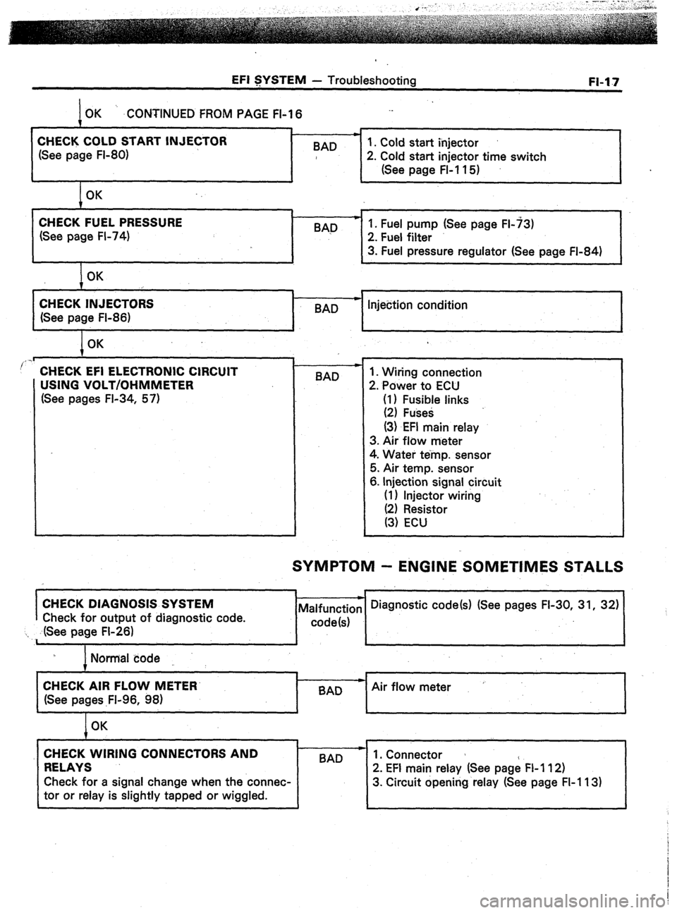
OK ‘. .CONTINUED FROM PAGE FI-I 6
m
CHECK COLD START INJECTOR
1. Cold start injector
(See page FI-80) BAD
2. Cold start injector time switch
(See page FL11 5)
OK FI-17
CHECK FUEL PRESSURE
(See page FI-74) BAD p 1. Fuel pump (See page FL73)
2. Fuel filter
3. Fuel pressure regulator (See page FI-84)
OK
CHECK INJECTORS
(See page FI-86) c
-
BAD Injection condition
I OK
..I
’ CHECK EFI ELECTRONIC CIRCUIT
USING VOLT/OHMMETER
(See pages FI-34, 57) BAD 1. Wiring connection
2. Power to ECU
(I) Fusible links
(2) Fuses
(3) EFI main relay
3. Air flow meter
4. Water temp. sensor
5. Air temp. sensor
6. Injection signal circuit
(I 1 Injector wiring
SYMPTOM - ENGINE SOMETIMES STALLS
I
CHECK DIAGNOSIS SYSTEM
Check for output of diagnostic code.
‘I ,. ,dSee page FI-26)
I Normal code
I
CHECK AIR FLOW METER’
Air flow meter
(See pages .Fl-96, 98)
I
OK
CHECK WIRING CONNECTORS AND
RELAYS 1 BAD --
2’ EFI main relay (See page FI 112)
Check for a signal change when the connec- 3. Circuit opening relay (See page FI-113)
tor or relay is slightly tapped or wiggled.
Page 53 of 346
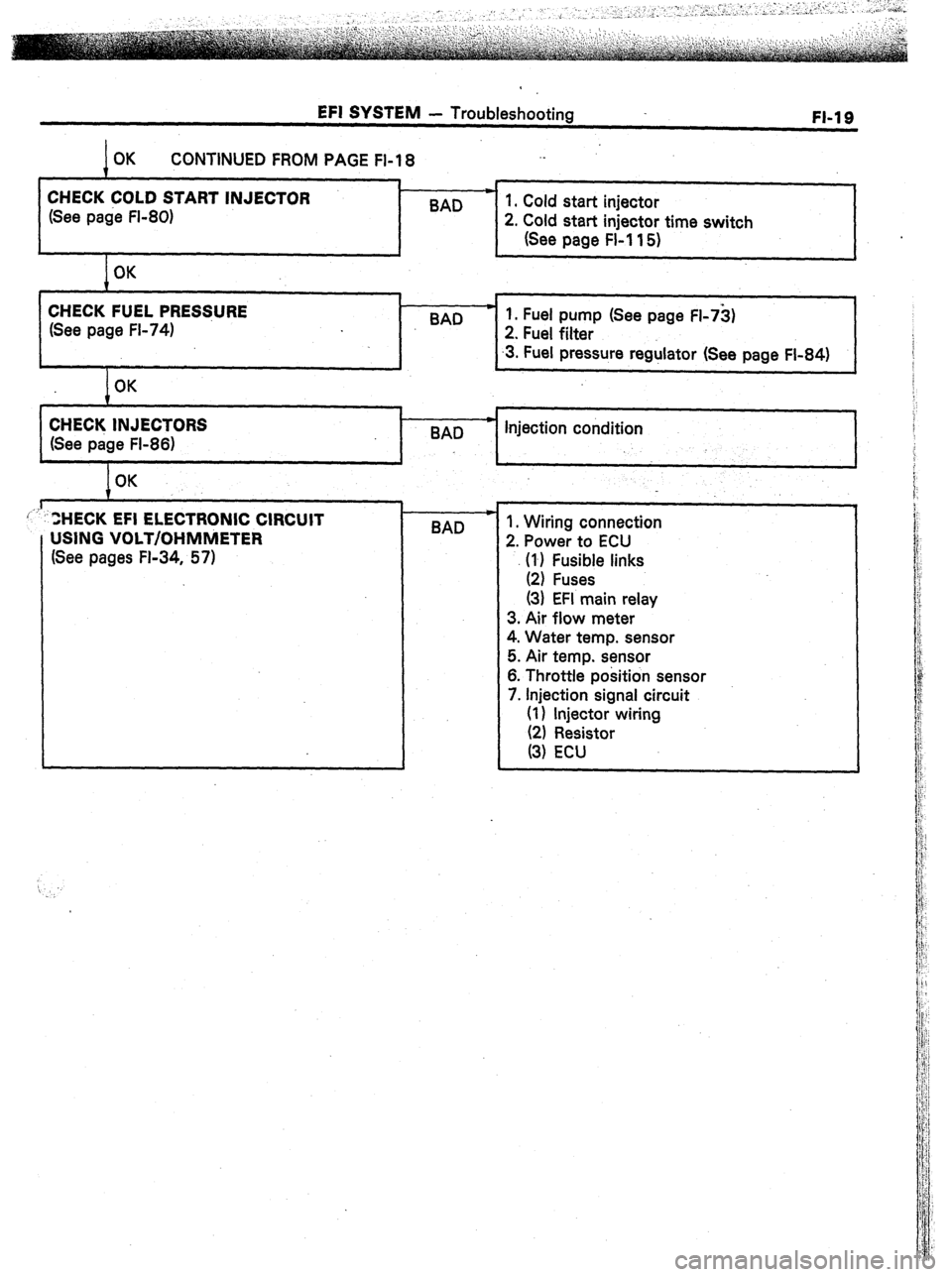
EFI SYSTEM - Troubleshooting
FI-19
CONTINUED FROM PAGE Fl-18 ._
t
CHECK COLD START INJECTOR *
(See page FI-80) BAD 1. Cold start injector
2. Cold start injector time switch
(See page FL11 5)
CHECK FUEL PRES$URE
(See page FL74) BAD c 1. Fuel pump (See page FI-73)
2. Fuel filter
.3. Fuel pressure regulator (See page FI-84)
I
I 1 c 4
/OK
I
CHECK INJECTORS
(See page FI-86) 8AD * Injection condition
I OK
L 1
ZHECK EFI ELECTRONIC CIRCUIT
USING VOLT/OHMMETER
(See pages FL34, 57) c
BAD 1. Wiring connection
2. Power to ECU
\‘l’, F;t;e links
(3) EFI main relay
3. Air flow meter
4. Water temp. sensor
5. Air temp. sensor
6. Throttle position sensor
7. Injection signal circuit
(1) injector wiring
Page 57 of 346
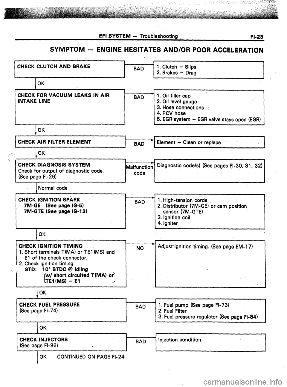
EFI SYSTEM - Troubleshooting
FI-23
SYMPTOM - ENGINE HESITATES AND/OR POOR ACCELERATION
CHECK CLUTCH AND BRAKE .
BAD
I
I 1
1 OK
CHECK FOR VACUUM LEAKS IN AIR
INTAKE LINE
I OK BAD
I-
1. Clutch - Slips
2. Brakes - Drag
1. Oil filler cap
2. Oil level gauge
3. Hose connections :
4. PCV hose
5. EGR system - EGR valve stays open (EGR)
4
CHECK AIR FILTER ELEMENT
BAD Element - Clean or replace
I
,,: -. OK
7
. . 1 i , 1
CHECK DIAGNOSIS SYSTEM
Check for output of diagnostic code.
(See page FI-26) Malfunction
I-- code Diagnostic code(s) (See pages FI-30, 31, 32)
I
I I I J
1 Normal code
CHECK IGNITION SPARK
7M-GE (See page IO-61
7M-GTE (See page 16-12) .
BAD
I
I OK
CHECK IGNITION TIMING
1. Short terminals T(MA1 or TEl (MS) and
El of the check connector.
2. Check ignition timing.
‘i, STD: 10” BTDC @ Idling
I short circuited TiMA) or
I
I OK
CHECK FUEL PRESSURE
(See page Fl-74) 1. High-tension cords
2. Distributor (7M-GE) or cam position
sensor (7M-GTE)
3. Ignition coil
4. Igniter
NO Adjust. ignition timing. (See page EM- 17)
I
I
BAD
I
1. Fuel pump (See page Fl-73)
2. Fuel Filter
3. Fuel pressure regulator (See page Fl-84)
1
OK
CHECK INJECTORS
(See page FI-86) BAD c Injection condition
OK CONTINUED ON PAGE FI-24
Page 71 of 346
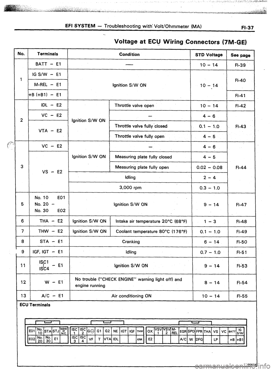
EFI SYSTEM - Troubleshooting with’ Volt/Ohmmeter (MA) FI-37
Voltage at EClJ Wiring .Connectors (TIM-GE)
IO. Terminals
Condition STD Voltage
See page
BATT - El
10 - 14 FI-39
IG S/W - El
1 FI-40
M-REL - El
Ignition S/W ON 10 - 14
+B (+Bl) - El FI-41
IDL - E2 Throttle valve open 10 - 14 FI-42
vc - E2 -
4-6
2 Ignition S/W ON -
Throttle valve fully ‘closed 0.1
- 1.0 FI-43
VTA - E2
Throttle valve fully open 4-5
VC - E2 4-6
Ignition S/W ON
Measuring plate fully closed 4-5
3 Measuring plate fully open 0.02 - 0.08 FI-44
VS - E2
Idling 2-4
3,000 rpm 0.3 - 1.0
No. 10 EOI
5 No. 20 - Ignition S/W ON 9 - 14 FI-47
No. 30 E02
6 THA - E2 Ignition S/W ON Intake air temperature 20°C (68°F) 1 -3 FI-48
7 THW - E2 Ignition S/W ON Coolant temperature 80°C II 76’F) 0.1 - 1 .O
FI-49
8 STA - El Cranking
6 - 14 FI-50
9 IGF, IGT - El Idling
0.7 - 1.0 FI-5 1
11 ISCI
I&4 - El Ignition S/W ON 9-14 Fl-53
12 W - El No trouble (“CHECK ENGINE” warning light off) and
engine running 8 - 14 FI-54
13 A/C - El Air conditioning ON IO - 14 FI-55
ECU Terminals
‘~,~] E2 4
/UC W:G up +S :,:I
N:y Is’ Is’ GO Gl G2 NE IGT IGF THW OX “s, “;“riL EGR SPD FPR THA VS VC BATT IG
F1057
Page 72 of 346
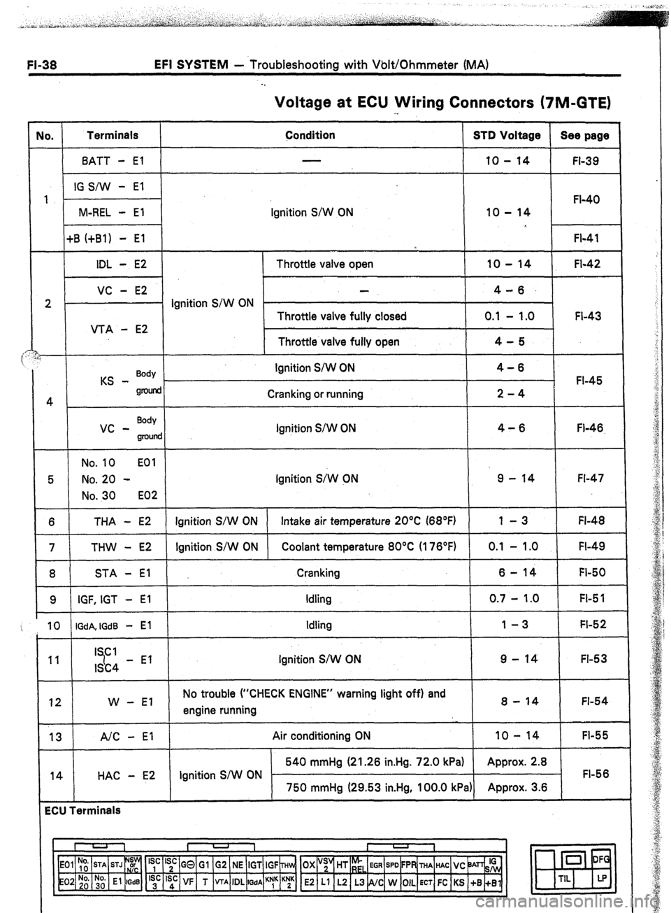
EFI SYSTEM - Troubleshooting with Volt/Ohmmeter (MA)
. .
Voltage at ECU Wiring Connectors (7M-GTE)
No. Terminals
Condition STD Voltage Sea page
BATT - El 10 - 14
FI-39
IG S/W - El
1
FI-40
M-REL - El Ignition S/W ON 10 - 14
+B (+Bl) - El
FI-41
*
IDL - E2 Throttle valve open 10 - 14 FI-42
VC - E2 4-6.
2 . Ignition S/W ON
Throttle valve fully closed 0.1 - 1.0 FI-43
VTA - E2
Throttle valve fully open 4-5
i
KS - Body Ignition S/W ON 4-6
FI-45
gnMid
4 Cranking or running 2-4
vc - Body
Ignition S/W ON 4-6
groulld Fl-46.
No. 10 EOl
5 No. 20 - Ignition S;W CN 9 - 14 Fl-47
No. 30 E02
6 THA - E2 Ignition S/W ON Intake air temperature 20°C (68°F) 1 -3 FI-48
7 THW - E2 Ignition S/W ON Coolant temperature 80°C (176°F) 0.1 - 1 .O FI-49
8 STA - El Cranking 6-14 FI-50
9 IGF, IGT - El Idling 0.7 - 1.0 FI-5 1
10 IGdA, IGdB - El Idling 1-3 FI-52
11 I Cl
7 9 - 14 FI-53
ISC4 - El Ignition S/W ON
12 W - El No trouble (“CHECK ENGINE” warning light off) and
engine running 8 - 14 FI-54
13 A/C - El
14 HAC - E2 Air conditioning ON 10 - 14
FI-55
540 mmHg (21.26 in.Hg. 72.0 kPa) Approx. 2.8
Ignition S/W ON FI-56
750 mmHg (29.53 in.Hg, 100.0 kPa) Approx. 3.6
ECU Terminals
I U 1 I -
I
1
‘yc ‘;c GQ Gl G2 NE IGT IGF ~Hln, OX “;’ HT r;,
EGR SPD FPR THA HAC VC ‘JAn& 0 DF
‘;’ ‘sd: VF T VTA IDL
WA ““1” K;K E2 Ll L2 L3 NC W OIL ECT FC KS +B +Bl m
TIL LP