Page 160 of 346
FI-126 EFI SYSTEM - Electronic Control &stem
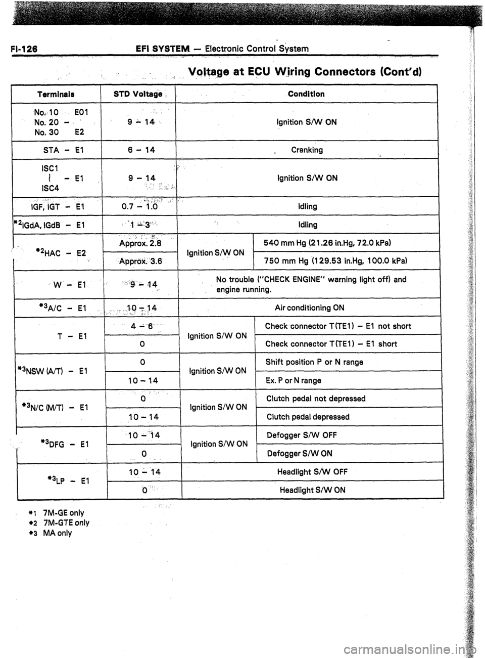
Voltage at ECU W.jring Connectors (Cont’d)
.:. .I, ,,
Termlnals
Nov
10 EOI
No. 20 -
No. 30
E2
STD Voltage
6 L ,4-,: Condition
Ignition S/W ON
STA - El
ISCI
I -El
ISC4
,, : :
IGF, IGT - .E-1
*‘IGdA, lGd8 - El
:
‘2HAC - E2 6 - 14
9 - 14
-
I, .., ,i,
o .,.- i.;&& ,; ::
:,, ;;:3%
. . 1
Approx: 2.8
- Ignition S/w ON
Approlr. -3.6 L Cranking
,
Ignition S/W ON
Idling
Idling
540 mm Hg (21.26 in.Hg, 72.0 kPa)
750 mm Hg (I 29.53 in.Hg, 100.0 kPa)
W - El ‘: :g L ;I 4
: No trouble (“CHECK ENGINE” warning light off) and
engine running.
1
*3A/C - El .,. . :.llC 1~14 Air conditioning ON
>-
T - El 4A.6
Check connector T(TE1) - El not short
Ignition S/W ON
0 Check connector TfTEl) - El short
*3NSW (A/T) - El
*3N/C Uvl/TI -
El 0
Shift position P or N range
Ignition S/W ON
IO-14 Ex. P or N range
0: Clutch pedal not depressed
- Ignition S/W ON .
IO-14 Clutch pedal depressed
..-
I 1044 1 1 Defogger S/W OFF
I
“3DFG - El
“3LP - El 0
10 - 14
j) ‘. Ignition S/W ON
Defogger S/W ON
Headlight S/W OFF
Headlight S/W ON
*I 7M-GE only
*2 7M-GTE only
*3 MA only
Page 161 of 346
EFI SYSTEM - Electronic Control. System
FL127
ECU Wiring . .
3.
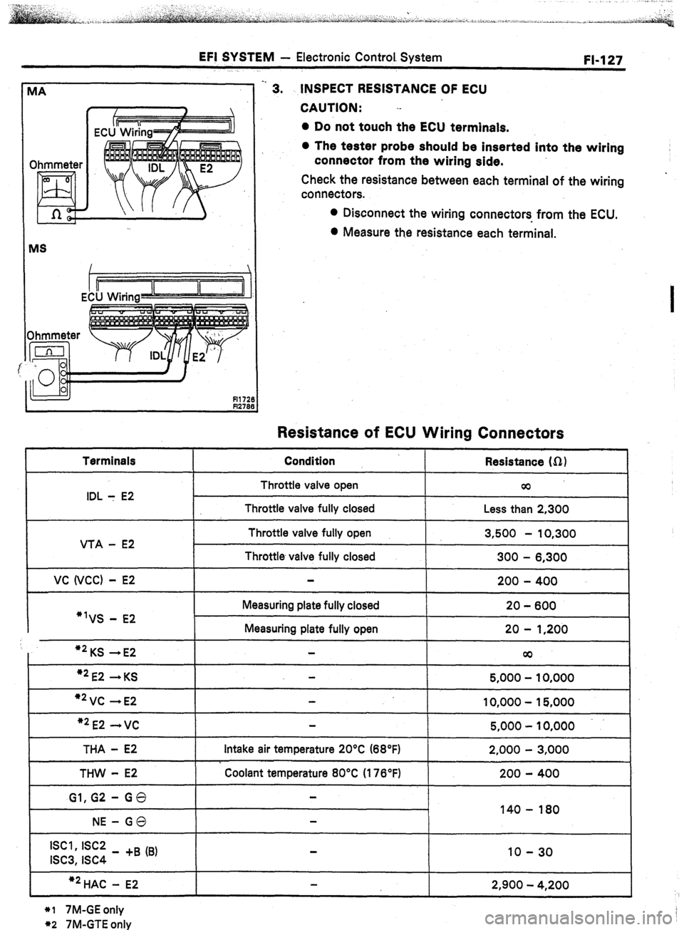
INSPECT RESISTANCE OF ECU
CAUTION: .-
l Do not touch the ECU terminals.
0 The tester probe should be inserted into the wiring
connector from the wiring side.
Check the resistance between each terminal of the wiring
connectors.
l Disconnect the wiring connectors from the ECU.
0 Measure th.e resistance each terminal.
I
Resistance of ECU Wiring Connectors
Terminals Condition
. I Resistance Ifi)
I
IDL : E2
VTA - E2
VC WCC) - E2 Throttle valve open
Throttle valve fully closed
Throttle valve fully open
Throttle valve fully closed cc
Less than 2,300
3,500 - 10,300
300 - 6,300
200 - 400
*‘VS - E2 Measuring plate fully closed
Measuring plate fully open 20 - 600
20 - 1,200
I *2KS -E2 co I I I
“2E2 +KS -
5,000 - 10,000 I
I
“2VC -E2
10,000 - 15,000
I “2E2 -+VC
I I 5,000 - 10,000 I
THA - E2
THW - E2
Gl,G2 - GO
NE-GO Intake air temperature 20°C (68’FI
. Coolant temperature 80°C (176°F) 2,000 - 3,000
200 - 400
140 - 180
Iscl, I%2 _ +a (8)
ISC3, ISC4 10-30
+2 HAC - E2 2,900 - 4,200
*I 7M-GE only
*2 7M-GTE only
Page 181 of 346
ENGINE MECHANICAL! Y) Engine Tune-up
Qy r\:y 9,.
, ,. . .,
1. 1. ., I ,,.,q,, ./. . . .
. . . . . . . J>
,; ..1’- -INSPECTION AND ADJUSTMENT OFIDLE
I
$‘,’ ,, :.. ,:
MIXTURE (w/o TWC)
2,
.: .,;.
4.
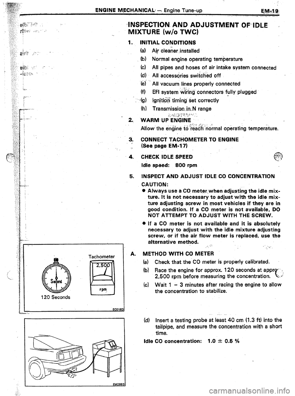
5. tNSPECT AND ADJUST IDLE CO CONCENTRATION
120 Seconds Tachometer
$0
H v
EC016
,
A. INITIAL CONDITIONS
(a) Ajr cleaner Jnstalled
(b) Normal engine operating temberature
(cf All pipes and hoses of air intake system connected
(d) All accessories switched off
‘6) All vacuum lines properly connected
(f) EFI system~‘w&g connectors fully plugged
c(g) I.gnitio$ timing set correctly
(h) Transmission. i.n,.N range
CONNECT TACHCBMETER TO ENGINE
(See page EM-171
CHECK IDLE SPEED
Idle speed: 800 rpm
CAUTION:
a Always use a CO meter,.,when adjusting the idle mix-
ture. It is not necessary to adjust with the idle mix-
ture adjusting screw in. most vehicles if they are in
good condition. If a CO meter is not available, DO
NOT ATTEMPT TO ADJUST WITH THE SCREW.
l If a CO meter is not available and it is absolutely
necessary to adjust with the idle mixture adjusting
screw, or if the air flow meter is replaced, use the
alternative method.
~, r’.
’ _‘i..
METHOD WITH CO METER
(a) Check that the CO meter is properly calibrated.
(b) Race the engine for approx. 120 seconds at appr 1,
2,500 rpm before measuring the concentration. r
‘-..*
(c) Wait 1 - 3 minutes after racing the engine to allow
the concentration to stabilize.
(df Insert a testing probe at least 40 cm (1.3 ft) into the
tailpipe, and measure the concentration with a short
time.
Idle CO concentration: 1.0 -t- 0.5 %
Page 184 of 346
EM-22 ENGINE MECHANICAL - Engine Tune-up
INSPECTION OF IDLE HC/CO
CONCENTRATION (w/ TWC)
NOTE: This check method is used only to determine
whether or not the idle HWCO complies with regulations.
1. INSTALL CONDITIONS
(a) Air cleaner installed
(b) Normal engine operating temperature
(c) All pipes and hoses of intake system connected
(d) All accessories switches off
(e) All vacuum lines properly connected
NOTE: All vacuum hoses for EGR system etc. should be
properly connected
(f) EFI system wiring connectors fully p!ugged
(g) Ignition timing set correctly ‘.
(h) Transmission in “N” range
6) Tachometer and HWCO meter at hand and calibrated
2. WARM UP ENGINE
Allow the engine to reach normal operating temperature.
3. CONNECT TACHOMETER TO ENGINE
(See page EM- 17)
w ‘I” FI16C
4. CHECK IDLE SPEED
Idle speed :
7M-GE 700 rpm
7M-GTE 800 rpm
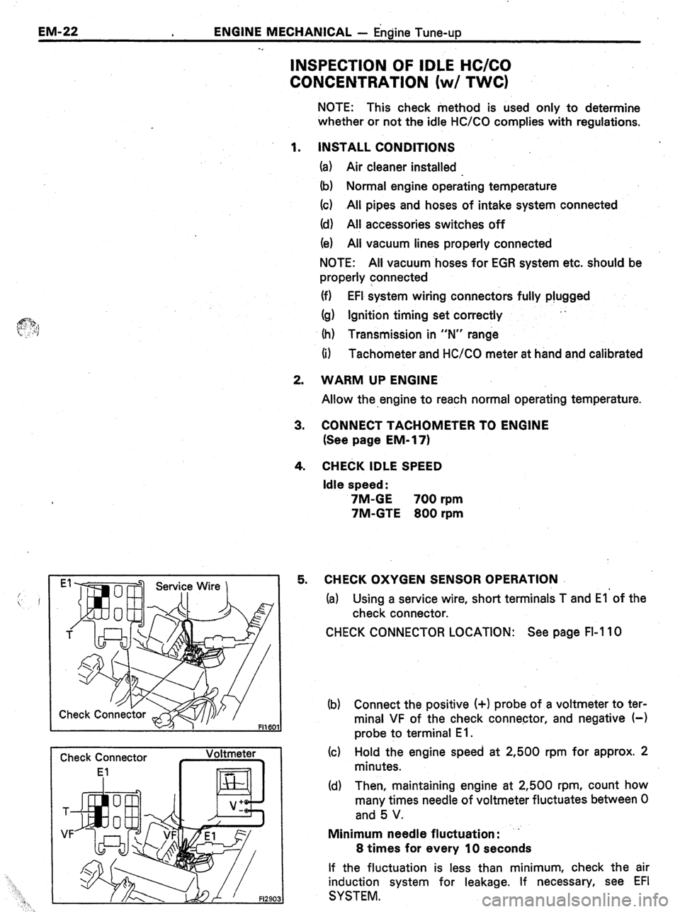
5. CHECK OXYGEN SENSOR OPERATION
(a) Using a service wire, short terminals T and El’of the
check connector.
CHECK CONNECTOR LOCATION: See page FI-I 10
(b) Connect the positive (+I probe of a voltmeter to ter-
minal VF of the check connector, and negative (-1
probe to terminal E 1.
(c) Hold the engine speed at 2,500 rpm for approx. 2
minutes.
(d) Then, maintaining engine at 2,500 rpm, count how
many times needle of voltmeter fluctuates between 0
and 5 V.
Minimum needle fluctuation : ’
8 times for every 10 seconds
If the fluctuation is less than minimum, check the air
induction system for leakage, If necessary, see EFI
SYSTEM.
Page 258 of 346
IQ-4
IGNITION SYSTEM - Ignition System Circuit
IGNlTlON SYSTEM CIRCUIT
7M-GE, Ignition Switch lanitian Cnil
AM2 30A
Fusible Link
MAIN 2.OL
(MA)
~“. _._. _ _..
AM29~2
I “i!l A II
I
(MS)
I
Spark Plug l-1 II
R Igniter
1
7M-GTE
I
Ignition Switch
AM2 30A
Fusible Link
MAIN 2.OL
Battery IG2
To Tachometer
1 f
Cam Position
Sensor
r--1
G2 IGT
NE
IGdA
NO
IGdB f
To Tachome:
n Spark Plug
Igniter
: I=
B
I=
Ignition Coil
It08
ELECTRONIC SPARK ADVANCE (ESA)
The ECU is programmed with data for optimum ignitio
timing under any and all operating conditions. Using dat
provided by sensors which monitor various engine func
tions (rpm,
intake air volume, eng. temperature, etc.) th
microcomputer (ECU) triggers the spark at precisely th
right instant.
Page 332 of 346
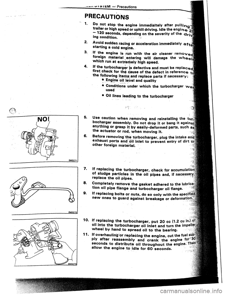
u EM3271
. .
1.
Do not stop the engine immedialtely after pullin
trailer or high speed or uphill driving. Idle the engin
- 126 seccnds, depending on the severity of the drf
ing condition, .,I
2.
Avoid sudden racing or acceleration immediately
starting a cold engine. aft
3.
If the engine is ‘run with the air cleaner remov
foreign material : entering Will damage the whe
which run’ at ext
4.
lf the turbocharger i‘s .defective and must be replac
first check for thd &use of the defect in referent
the foilowing ite&and replace parts if necessary:
l .Engine:oil level and quality
c ,. ,_. .^
. I, .: .’
c Conditions under which the turbocharger MI
used ..
c Oil lines leading to the turbocharger
PRECAUTIO.NS
5.
use caution when .removing and reinstalling the
bocharger assembly. Do not drop it or bang it
anything or grasp it by easily-deformed parts,
the actuator or rod, .when moving it.
6.
other foreign material.
7.
lf replacing the turbocharger, check for accumulati
of sludge particles in the oil pipes and, if necessary
replace the oil pipes.
8.
EM327:
allow the engine
to idle for 60 seconds.
. ,-