Page 303 of 346

A12 : SERVICE SPECIFICATIONS - Enaine.Mechanical
EN$W4~~~WlECHAN~CAL (
‘t&.gy,.::*,. : .,
Speclfrcations
r
: r’
: . .
‘-’ b- ~.
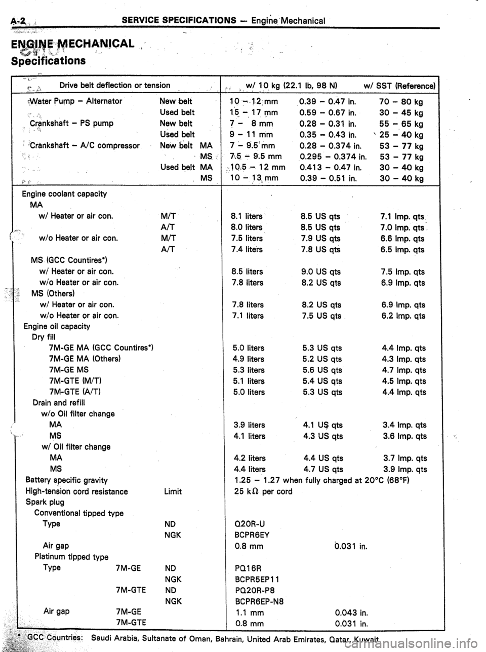
” Drive belt deflection or tension
. . . .,:
;Water Pump - Alternator New belt
,, ‘Crankshaft Used belt
- PS pump New belt
..!
Used belt
-Crankshaft - A/C compressor
New hit MA
,.
‘; MS
Used belt MA
<” : MS
Engine coolant capacity
MA
WI Heater or air con.
,.
w/o Heater or air con.
MS (GCC Countires’)
WI Heater or air con.
w/o Heater or air con.
MS (Others)
w/ Heater or air con.
w/o Heater or air con.
Engine oil capacity
Dry fill
7M-GE MA (GCC Countires’)
7M-GE MA (Others)
7M-GE MS
7M-GTE (M/T)
7M-GTE (A/T)
Drain and refill
w/o Oil filter change
MA
MS
w/ Oil filter change
MA
MS
Battery specific gravity
High-tension cord resistance
Spark plug
Conventional tipped type
We
Air gap
Platinum tipped type
Type 7M-GE
7M-GTE
Air gap 7M-GE
7M-GTE M/T
A/T
M/T
A/T
Limit
ND
NGK
ND
NGK
ND
NGK / w/ IO, kg (22.1 lb, 98 N) w/ SST (Reference)
,. .
IO 7 1.2:mm .0.39 - 0.47 in. 70 - 80 kg
I5 -, 17 mm 0.59 - 0.87 in. 30 - 45 kg
I- 8mm 0.28 - 0.31 in. 55 - 65 kg
3-llmm 0.35 - 0.43 in. ” 25 -‘40 kg
7 1 9.5‘mm 0.28 - 0.374 in. 53 - 77 kg
7;.5 - 9.5 mm 0.295 - 0.374 in. 53 - 77 kg
10.5 .- 12 mm 0.413 - 0.47 in. 30 - 40 kg
IO - 13.,mm
0.39 - 0.51 in. 30 - 40 kg
8.1 liters
8.0 liters.
7.5 liters
7.4 liters
8.5 liters
7.8 liters
7.8 liters
7.1 liters 8.5 US qts
8.5 US qts
7.9 us qts
7.8 US qts
9.0 us qts
8.2 US qts
8.2 US qts
7.5 us qts 7.1 Imp. qts
7.0 Imp. qts:
6.8 Imp. qts
6.5 Imp. qts
7.5 Imp. qts
6.9 Imp. qts
6.9 Imp. qts
6.2 Imp. qts
5.0 liters
4.9 liters
5.3 liters
5.1 liters
5.0 liters 5.3 us qts
5.2 US qts
5.6 US qts
5.4 us qts
5.3 us qts 4.4 Imp. qts
4.3 Imp. qts
4.7 Imp. qts
4.5 Imp. qts
4.4 Imp. qts
3.9 liters 4.1 US qts 3.4 Imp. qts
4.1 liters 4.3 us qts 3.6 Imp. qts
4.2 liters 4.4 us qts 3.7 Imp. qts
4.4 liters 4.7 us qts 3.9 Imp. qts
1.25 - 1.27 when fully charged at 20°C (68°F)
25 kn per cord
Q20R-U
BCPRGEY
0.8 mm b.03 1
PQ16R
8CPR5EPll
PQ20R-P8
BCPRGEP-N8 in.
1.1 mm 0.043 in.
0.8 mm 0.031 in.
,:‘GCC Countries:
~~ s; Saudi Arabia, Sultanate of Oman, Bahrain, United Arab Emirates, Qatar, Kuwait.
p;
.5&.,..‘ .,
gg&-&;,., ;.
Page 320 of 346
STARTER
f------h.
COMPONENTS
.r--%.--~ i
: _ :s’;‘ .
1.0 kW Type . . ..-c
-’ .-...._
Field Frame (Field Coil) A.-4..ep Bearing
I 2.
Retainer
1.4 kW Type Return’Spring
Bearing
4 O-Fling Bearing
End
Starter ‘Housing
) Non-reusable part
6 I
62 Return Spring
Page 322 of 346

_. I STARTING SYSTEM T Starter
ST-
-’ “’ .I
ST004
/
No continuity
ST0201 0
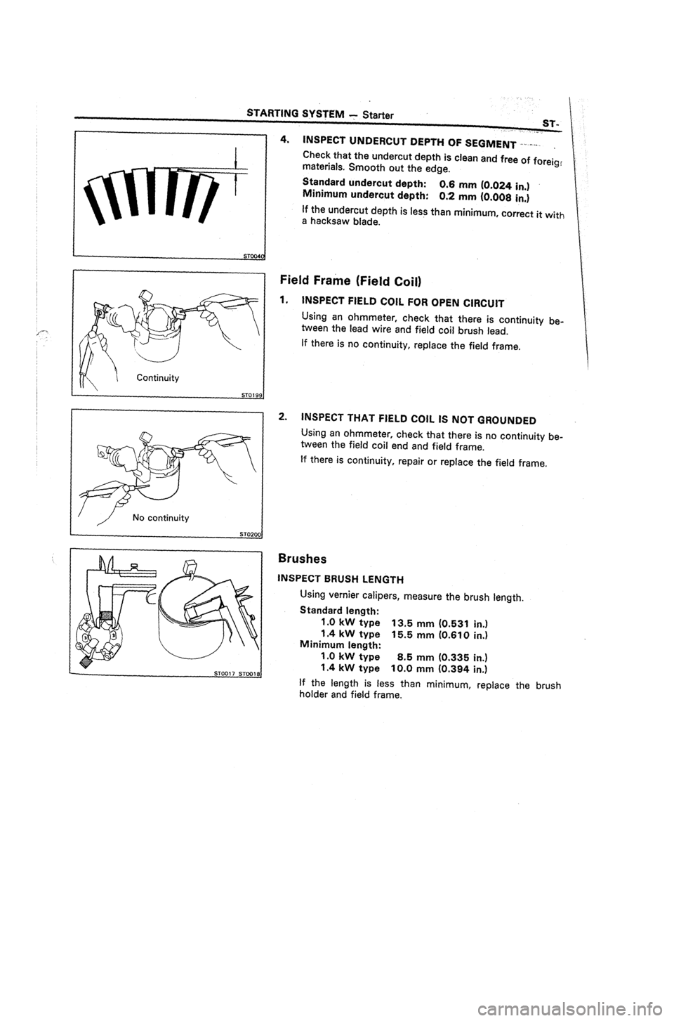
4. INSPECT UNDERCUT DEPTH OF SEGMENT I-.-.v-.
.
Check that the undercut depth is clean and free of foreig,
materials. Smooth out the edge.
Standard undercut depth:
Minimum undercut depth: 0.6 mm (0.024 in.)
0.2 mm (0.008 in.)
If the undercut depth is less than minimum, correct it
with
a
hacksaw blade.
Field Frame (Field Coil)
1.
INSPECT FIELD COIL FOR OPEN CIRCUIT
Using an ohmmeter, check that there is continuity be-
tween the lead wire and field coil brush lead.
If there is no continuity, replace the field frame.
2.
INSPECT THAT FIELD COIL IS NOT GROUNDED
Using an ohmmeter, check that there is no continuity be-
tween the field coil end and field frame.
If there is continuity, repair or replace the field frame.
Brushes
INSPECT BRUSH LENGTH
Using vernier calipers, measure the brush length.
Standard length:
1 .O kW type 13.5 mm (0.531 in.)
1.4 kW type 15.5 mm (0.610 in.)
Minimum length:
1.0 kW type 8.5 mm (0.335 in.)
1.4 kW type 10.0 mm (0.394 in.)
If the length is less than minimum, replace the brush
holder and field frame.
Page 324 of 346
. .
STARTINQ SYSTEM -Starter’
ST-9
I
STOGZI ST004
I
SST
0
I / Terminal c Continuity
ST0024,
Bearings
1.
INSPECT BEARINGS
Turn each bearing by hand while applying. inward force.
If resistance is felt or if the bearing sticks, replace the
bearing.
~2. IF NECESSARY, REPLACE BEARINQS
(a)
Using SST, remove the bearing.
SST 09286-46011
(b) Using SST and a press, press in a new front bearing.
SST 1 .O kw type 09285-76010
1.4 kw type 09201-41020
(c) Using a press, press in a new rear bearing,
Magnetic Switch
1.
PERFORM PULL-IN COIL OPEN CIRCUIT TEST
Using an ohmmeter, check that there is continuity be-
tween terminal 50 and C.
If there is no continuity, replace the magnetic switch
assembly.
2.
PERFORM HOLD-IN COIL OPEN CIRCUIT TEST
Using an ohmmeter, check that there is continuity be-
tween terminal 50 and the switch body.
If there is no continuity, replace the magnetic switch
assembly.
Page 330 of 346

x-2 TURBOCHARGER SYSTEM - Description
.
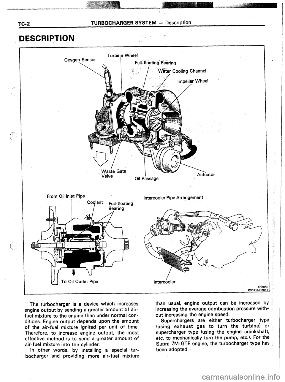
DESCRIPTION
-.
“
Oxygen
. Turbine Wheel
Sensor
.
I Full-floating Bearing
Valve
Oil P&sage
From Oil Inlet Pipe
Intercooler Pipe Arrangement
TdO
CSOll5 Fl2
The turbocharger is a device which increases
engine output by sending a greater amount of air-
fuel mixture to the engine than under normal con-
ditions. Engine output depends upon the amount
of the air-fuel mixture ignited per unit of time.
Therefore, to increase engine output, the most
effective method is to send a greater amount of
air-fuel mixture into the cylinder. than usual, engine output can be increased by
.
increasing the average combustion pressure with-
out increasing the engine speed.
Superchargers are either turbocharger type
(using exhaust gas to turn the turbine) or
supercharger type (using the engine crankshaft,
etc. to mechanically turn the pump, etc.). For the
Supra 7M-GTE engine, the turbocharger type has
been adopted.
In other words, by installing a special tur-
bocharger and providing more air-fuel mixture