Page 169 of 346
ENGINE MECHANICAL 2 Engine Tune-up
. . EM-7
ENGINE TUNE-UP
INSPECTlOi OF ENGINE COOLANT
(See page CO-51
INSPECTION OF ENGINE OIL
(See page LU-5)
t MA02931
INSPECTION Oi’AIR FILTER
(a) Visually check that the air cleaner element is not
excessively dirty, damaged or oily.
(b) Clean the element with compr&sed air.
First blow from back side thoroughly. Then blow off
the front side of the element.
INSPECTION OF BATTERY
(See page CH-3)
INSPECTION OF HIGH-TENSION CORDS
(See pages IG-6, 13)
INSPECTION OF SPARK PLUGS
(See pages 19-7 to 9)
INSPECTION OF DRIVE BELT
(See page CH-41
Page 175 of 346
ENGINE MECHANICAL &Engine Tune-up
EM-1 3
1
6. REMOVE CYLlNDER HEAD cOVERS
. .
(a) Remove the accelerator link.
(b) Disconn.ect the No.3 PCV hose.
(c) Remove the cylinder. head covers.
..:
s
’ .
*.
- ,; f...C?‘
;
.7. MEASURE VALVE CLEARANCE
.~. :. 1See+tep 3 oti page EM-91 3
6: ‘ADJUST VALVE CLEARANCE
j:
’ :
ISee ,tep 4 on pages EML9, 10)
: . i’... ..a .
; “.
~ ‘,
.
>*-* r-2. i.:
I / ‘.. . . 9. RFCHECK’ VALVE CLEARANCE
,y
10. INSTALL CYLiNDER HEAD COVERS
(See pages EM-59,601 ,_ .:
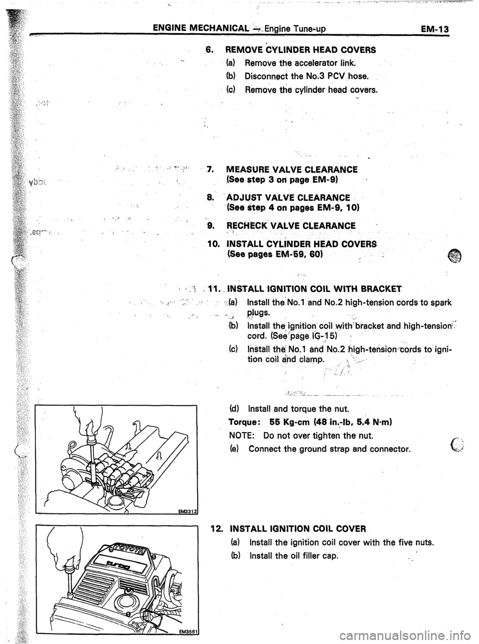
, ,-‘G j i rl.1. IN&ALL.lGNITION COIL WITH BRACKET
< .‘. ,_ ..- ,, ,,C’
:,la) Install theNo. and No.2 high-tension cords to spark
.. :I
l$w. .
._ i
$) &tall the ignition’coil withbracket and high-tension;.
cord. (Seepage I’C-,y 5)’ ;
(c) Install the No.‘l and No.2 high-tensioncords to igni-
tion coil and clamp. ,. ‘. “-. _
.;;
‘. ;
6, ..: ,-
.: .,,.. ‘y,’ I,.
(d) Install and torque the nut.
Torque : 55 Kg-cm (48 in..-lb, 5.4 Nnrn)
NOTE: Do not over tighten the nut.
(e) Connect the ground strap and connector.
12. INSTALL IGNITION COIL COVER
(a) Install the ignition coil cover with the five nuts.
fb) Install the oil filler cap.
Page 179 of 346
ENGINE MECHANICAL. - Engine Tune-up
EM-?1 7.
INS’PECTIOlil ‘AhiD ADJUSTMENT O:F .-
IGNITION TIMING
1. VriARiiA. UP ENGINE.
Allow the engine to. reach normal operating temperature.
2.
CbNNECT TACHOMETER AND TIMING LIGHT TO
ENGINE
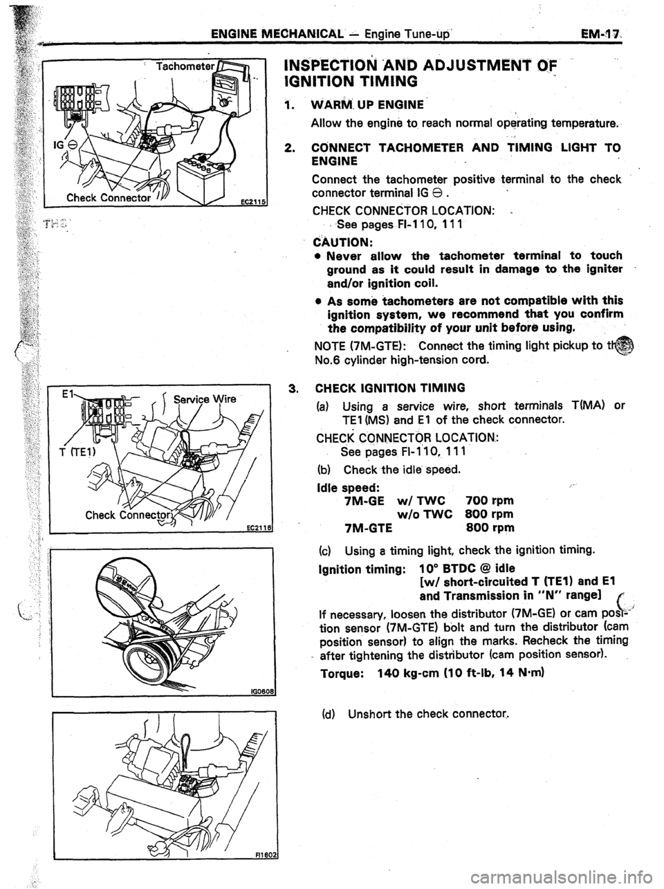
Connect the tachometer positive terminal to the check
connector terminal IG 0 .
CHECK CONNECTOR LOCATION: .,
s See pages FI-110, 111
CAUTION:
l Never allow the tachometer terminal to touch
ground as it could result in damage to the igniter
and/or ignition coil.
, 4% 3.
EC21 18
s As some tachometers are not compatible with this
ignition system, we recommend that you confirm
the compatibility of your unit before using.
NOTE (7M-GTE): Connect the timing light pickup to t
No.6 cylinder high-tension cord.
CHECK IGNITION TIMING
(a) Using a service wire, short terminals T(MA) or
TEI (MS) and El of the check connector.
CHEC,K CCNNECTOR LOCATION.:
See pages FI- 1’10, 111
(b) Check the idle. speed.
Idle speed: /-
7M-GE w/ TWC 700 rpm
w/o TWC 800 rpm
7M-GTE 800 rpm
(c) Using a timing light, check the ignition timing.
Ignition timing: IO” BTDC @ idle
[w/ short-circuited T (TEl) and El
and Transmission in “N” range]
c,
If necessary, loosen the distributor (7M-GE) or cam posz-’
tion sensor (7M-GTE) bolt and turn the distributor (cam
position sensor) to align the marks. Recheck the timing
- after tightening the distributor (cam position sensor).
Torque: 140 kg-cm (10 ft-lb, 14 N-m)
(cl) Unshort the check connector.
Page 188 of 346
EM-26 ENGINE MECHANICAL - Compression Check
d
COMPRESSION CHECK
NOTE: If there is lack of power, excessive oil consump-
tion or poor fuel mileage, measure the cylinder compres-
sion pressure.
(7M-GE)
1.
2.
3.
4.
5.
6. REMOVE SPARK PLUGS (See page IO-71
7.
EM3003
WARM UP ENGINE
DISCONNECT COLD START INJECTOR CONNECTOR
DISCONNECT SOLEtiOlD RESISTOR CONNECTOR
DISCONNECT DISTRIBUTOR CONNECTOR
REMOVE THROTTLE BODY
(a) Remove the PCV hose.
(b) Disconnect the water by-pass hoses and plug the
hose end.
(c) Disconnect following hoses:
. fwl EGR)
VSV hoses
. (wl TWC)
BVSV hoses
. (w/ EGR)
EGR vacuum modulator hoses
l No.7 air hose
id) Disconnect the throttle position sensor connector.
(e) Remove the throttle body bracket(s).
(f) Remove the four bolts, throttle body and gasket.
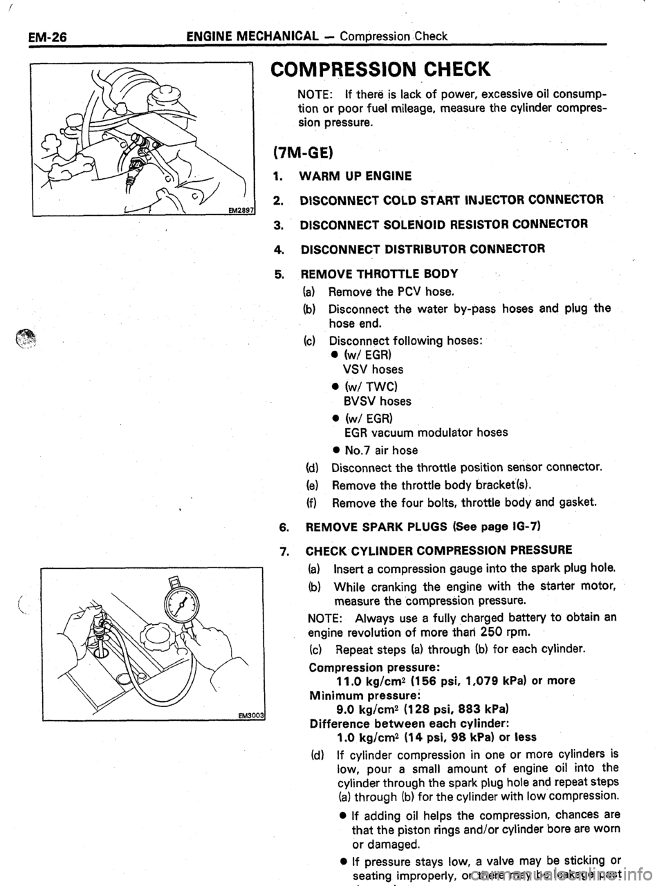
CHECK CYLINDER COMPRESSION PRESSURE
(a) Insert a compression gauge into the spark plug hole.
(b) While cranking the engine with the starter motor,
measure the compression pressure.
NOTE: Always use a
fully charged battery to obtain an
engine revolution of more than 250 rpm.
(c) Repeat steps Ia) through Ib) for each cylinder.
Compression pressure:
11.0 kg/cm2 (156 psi, 1,079 kPa) or more
Minimum pressure:
9.0 kg/cm2 (128 psi, 883 kPa)
Difference between each cylinder:
1 .O kg/cm2 (14 psi, 98 kPa) or less
(d) If cylinder compression in one or more cylinders is
low, pour a smali amount of engine oil into the
cylinder through the spark plug hole and repeat steps
(a) through (b) for the cylinder with low compression.
0 If adding oil helps the compression, chances are
that the piston rings and/or cylinder bore are worn
or damaged.
0 If pressure stays low, a valve may be sticking or
seating improperly, or there may be leakage past
the gasket.
Page 189 of 346
ENGINE MECHANICAL 1 Compression Ctwck
;
EMy27.
,* I,, ._ ,. .,
. . . . . Ij,_
--.
(7M-GTE)
1. WARM UP ENGINE
2. DISCONNECT SOLENOID RESISTOR CONNECTOR
3. DISCONNECT CAM POSITION SENSOR CONNECTOR
’ ’
F5129,
4. REMOVE NO.1 AIR CLEANER HOSE
5. REMOVE PCV PIPE
‘1 6. REMOVE IGNITION COIL
(See steps 4, 5 on page EM-121
7. REMOVE SPARK PLUGS (See page IO-121 .
‘_
-.
8. CHECK CYLlNDER COMPRESSION PRESSURE
(See step 7 on page EM-261
Compression pressure:
10.0 kg/cm2 (142 psi, 981 kPa) or more
Minimum pressure:
.
9.0 kg/cm2 (128 psi, 883.kPa)
Difference between each cylinder:
1 .O kg/cm2 (14 psi, 98 kPa1 or less
Page 193 of 346
ENGINE MECHANICAL - Timing Belt
Socket Wrench
NO!
1
15. REMOVE CRANKSHAFT TIMING .PULLEY
Using SST and a .socket wrench, remove the crankshaft-
timing pultey.
SST 09213-60017
16. REMOVE OIL PUMP DRtVE PULLEY
Using a screwdriver to hold the pulley, remove the pulley
bolt and pulley.
INSPECTION Oi COMPONENTS
1.
tNSPECT TlMlNG BELT
CAUTION :
l Do not bend, twist or turn the belt inside out.
l Do not allow the belt to come into contact with oil,
water or steam.
l Do not utilize belt tension when installing or remov-
ing the set bolt of the camshaft timing pulley.
If there are defects as shotin in the figures. Check the
foljowing points and replace the timing belt if necessary.
(a) Premature parting
l Check for proper installation.
l Check the timing belt cover gasket for damage
and proper installation.
(b) If the belt teeth are crackeb or damaged, check to
see if the camshaft is locked.
Page 209 of 346
i ’
‘
ENGINE MECHANICAL - Cylinder Head
EM-47
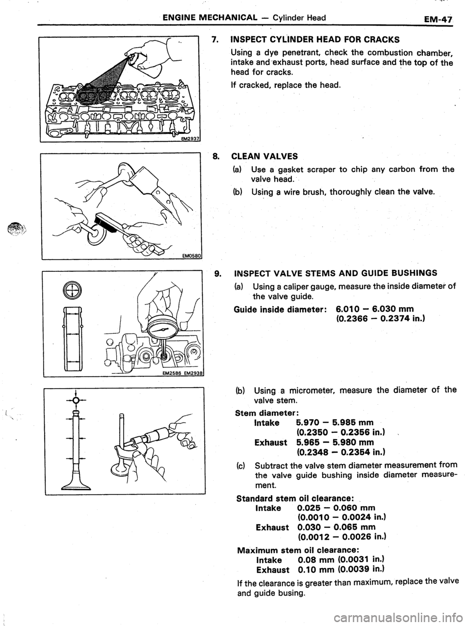
INSPECT CYLINDER HEAD FOR CRACKS
Using a dye penetrant, check the combustion chamber,
intake and-exhaust ports, head surface and the top of the
head for cracks.
if cracked, replace the head. 8.
9. CLEAN VALVES
(a) Use a gasket scraper to chip any carbon from the
valve head.
(b) Using a wire brush, thoroughly clean the valve.
INSPECT VALVE STEMS AND GUIDE BUSHINGS
(a) Using a caliper gauge, measure the inside diameter of
the valve guide.
Guide inside diameter:
6.010 - 6.030 mm
(0.2366 - 0.2374 in.)
EM2586 EM2931
(b) Using a micrometer, measure the diameter of the
valve stem.
Stem diameter:
Intake 5.970 - 5.985 mm
(0.2350 - 0.2356 in.) _
Exhaust 5.965 - 5.980 mm
(0.2348 - 0.2354 in.)
(c) Subtract the valve stem diameter measurement from
the valve guide bushing inside diameter measure-
ment.
Standard stem oil clearance:
Intake 0.025 - 0.060 mm
(0.0010 - 0.0024 in.)
Exhaust 0.030 - 0.065 mm
(0.0012 - 0.0026 in.)
Maximum stem oil clearance:
Intake 0.08 mm (0.0031 in.)
Exhaust 0.10 mm (0.0039 in.)
If the clearance is greater than maximum, replace the valve
and guide busing.
Page 215 of 346
ENGINE MECHANICAL - Cylinder Head
L Et.4294
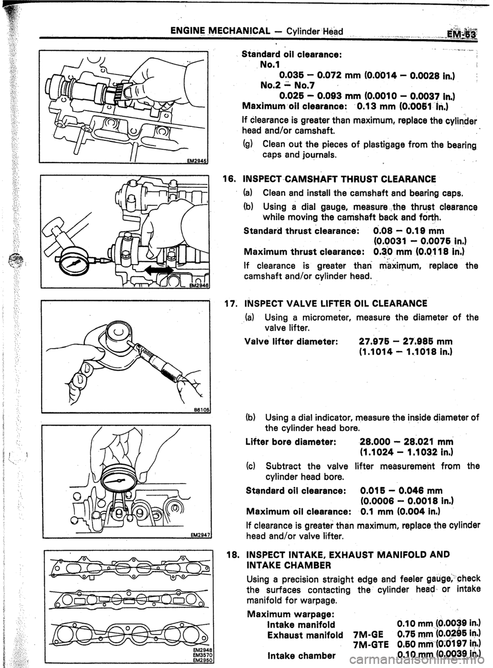
Standard oil clearance:
No.1 ... ..“..” .._.
0.036 - 0.072 mm (0.0014 - 0.0028 in,)
;
No.2 ii. No.7
0.025 - 0.093 mm (0.0010 - 0.0037 in.)
Maximum.oil clearance: 0.13 mm (0;0061 ‘hi.)
If dlearance is greater than maximum, replace the cylinder
head and/or camshaft.
(g) Clean out the pieces of plastigage from the bearing
caps and journals.
18. INSPECT-CAMSHAFT THRUST CLEARANCE
(a) Clean and install the camshaft and bearing caps.
(b) Using a dial gauge, measure
while moving the camshaft back and forth.
Standard thrust clearance’: 0.08 - 0.18 mm
(Q.9031 - 0.0976 in.)
Maximum thrust clearance: 0.30 mm IO.01 18 in.)
If clearance is greater than maximum, replace the
camshaft and/or cylinder head.
17. INSPECT VALVE LIFTER OIL CLEARANCE
.(a) Using a micrometer, measure the diameter of the
valve lifter.
Valve lifter diameter: 27.975 - 27.885 mm
(1.1014 - 1.1018 in.)
(b) Using a dial indicator, measure the inside diameter of
the cylinder head bore.
Lifter bore diameter: 28.000 - 28.021 mm
(1 .1024 - 1 .1032 in.)
(4 Subtract the valve lifter measuremeht from the
cylinder head bore.
Standard oil clearance: 0.015 - 0.048 mm
(0.0008 - 0.0018 in.)
Maximum oil clearance: 0.1 mm (0.004 in.)
If clearance is greater than maximum, replace the cylinder
head and/or valve lifter.
EM2948
EM3570
18. INSPECT INTAKE, EXHAUST MANIFOLD AND
INTAKE CHAMBER
Using a precision straight edge and feeler gauge;-check
the surfaces contacting the cylinder head, or intake
manifold for warpage.
Maximum warpage:
Intake manifold 0.10 mm (0.0039 in.)
Exhaust manifold IM-GE 0.75 mm (0.0295 in.)
7M-GTE 0.60 mm (OiOlQ7 in.)
Intake chamber 0.10 mm (0.0039 in.)
- .,, ,. 1. & ._i ^..s^..r*.., “,A