1987 TOYOTA CELICA check oil
[x] Cancel search: check oilPage 69 of 346
EFI SYSTEM - Troubleshooting with Volt/Ohmmeter (MA)
FI-35
. .
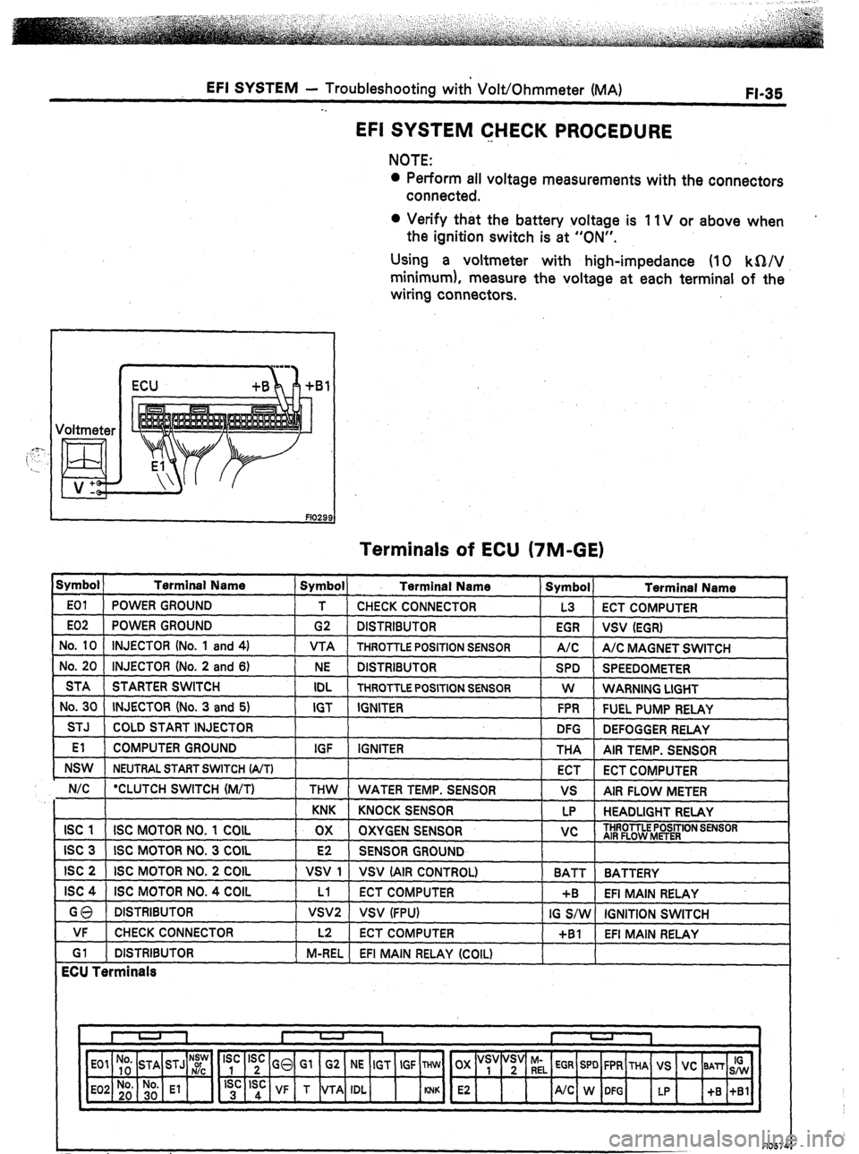
EFI SYSTEM CHECK PROCEDURE
NOTE:
l Perform all voltage measurements with the connectors
connected.
0 Verify that the battery voltage is 11V or above when
the ignition switch is at “ON”.
Using a voltmeter with high-impedance (IO kQ/V
minimum), measure the voltage at each terminal of the
wiring connectors.
I ) ECU +B
Terminals of ECU (7M-GE)
Symbol ) Terminal Name
E01 POWER GROUND
E02 POWER GROUND
No. 10 INJECTOR (No. 1 and 4)
No. 20 INJECTOR (No. 2 and 6)
STA STARTER SWITCH
No. 30 INJECTOR (No. 3 and 5)
STJ COLD START INJECTOR
El COMPUTER GROUND
NSW NEUTRAL START SWITCH (A/T)
N/C *CLUTCH SWITCH (M/T) 1 Symbol) Terminal Name
T CHECK CONNECTOR
G2 DISTRIBUTOR
VTA THROTTLE POSITION SENSOR
NE DISTRIBUTOR
IDL THROTTLE POSITION SENSOR
IGT IGNITER
IGF IGNITER
THW WATER TEMP. SENSOR Symbol
Terminal Name
L3 ECT COMPUTER
EGR
vsv (EGR)
A/C A/C MAGNET SWITCH
SPD SPEEDOMETER
W WARNING LIGHT
FPR FUEL PUMP RELAY
DFG
DEFOGGER RELAY
THA
AIR TEMP. SENSOR
ECT
ECT COMPUTER
vs AIR FLOW METER
KNK KNOCK SENSOR LP HEADLIGHT RELAY
ISC 1 ISC MOTOR NO. 1 COIL ox OXYGEN SENSOR vc THROTTLE POSITION SENSOR
AIR FLOW METER
ISC 3 ISC MOTOR NO. 3 COIL E2 SENSOR GROUND
ISC 2 ISC MOTOR NO. 2 COIL VSV 1 VSV (AIR CONTROL)
BATT BATTERY
ISC 4 ISC MOTOR NO. 4 COIL Ll ECT COMPUTER +B EFI MAIN RELAY
GQ DISTRIBUTOR VSVP VSV (FPU) IG S/W IGNITION SWITCH
VF CHECK CONNECTOR
Gl DISTRIBUTOR
ECU Terminals 1 L2 ECT COMPUTER
+Bl EFI MAIN RELAY
1 M-REL EFI MAIN RELAY (COIL)
*For cruise control
F10574
Page 70 of 346
FI-36 EFI SYSTEM - Troubleshooting with VoltjOhmmeter (MA)
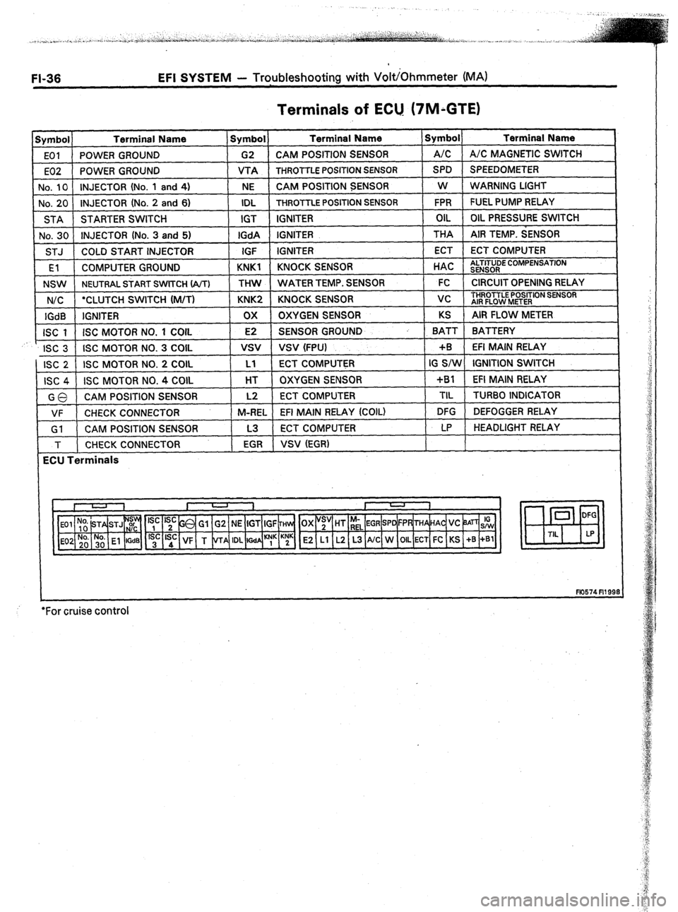
Terminals of ECU. (7M;GTE)
Symbol Terminal Name Symbol Terminal Name Symbol Terminal Name
EOI POWER GROUND G2 CAM POSITION SENSOR A/C A/C MAGNETIC SWITCH
E02 POWER GROUND VTA
THROTTLE POSITION SENSOR SPD SPEEDOMETER
No, 10 INJECTOR (No. 1 and 4)
NE CAM POSITION SENSOR W
WARNING LIGHT
No. 20 INJECTOR (No. 2 and 6) IDL
THROTTLE POSITION SENSOR FPR FUEL PUMP RELAY
STA STARTER SWITCH IGT IGNITER OIL OIL PRESSURE SWITCH
No. 30 INJECTOR (No. 3 and 5) IGdA IGNITER THA AIR TEMP. SENSOR
STJ COLD START INJECTOR
IGF IGNITER ECT ECT COMPUTER
rEl COMPUTER GROUND KNKl KNOCK SENSOR
t HAC 1 tl
NSW
NEUTRAL START SWITCH (A/T) THW WATER TEMP. S
N/C ‘CLUTCH SWITCH (M/T) KNK2 KNOCK SENSOR 1 vc ) THROTTLE
AIR
FLOW I
LTITUDE COMPENSATION
, .xNSOR
ENSOR 1 FC 1 CIRCUITOPENING RELAY I
IGdB IGNITER ox OXYGEN SENSOR KS AIR FLOW METER
ISC 1 ISC MOTOR NO. 1 COIL E2 SENSOR GROUND BATT BATTERY
r
ISC 3 ISC MOTOR NO. 3 COIL
vsv VSV (FPU) +B EFI MAIN RELAY
ISC 2 ISC MOTOR NO. 2 COIL Ll ECT COMPUTER IG S/W IGNITION SWITCH
ISC 4 ISC MOTOR NO. 4 COIL HT OXYGEN SENSOR +Bl EFI MAIN RELAY
GO CAM POSITION SENSOR L2 ECT COMPUTER TIL
TURBO INDICATOR
VF CHECK CONNECTOR M-REL
EFI MAIN RELAY (COIL) DFG DEFOGGER RELAY
Gl CAM POSITION SENSOR L3 ECT COMPUTER LP HEADLIGHT RELAY
T CHECK CONNECTOR
EGR VSV (EGR)
ECU Terminals
E2 Ll L2 L3 A/C W OIL ECT FC KS +B +Bl
+
F10574 Fll 99:
*For cruise control
Page 72 of 346
EFI SYSTEM - Troubleshooting with Volt/Ohmmeter (MA)
. .
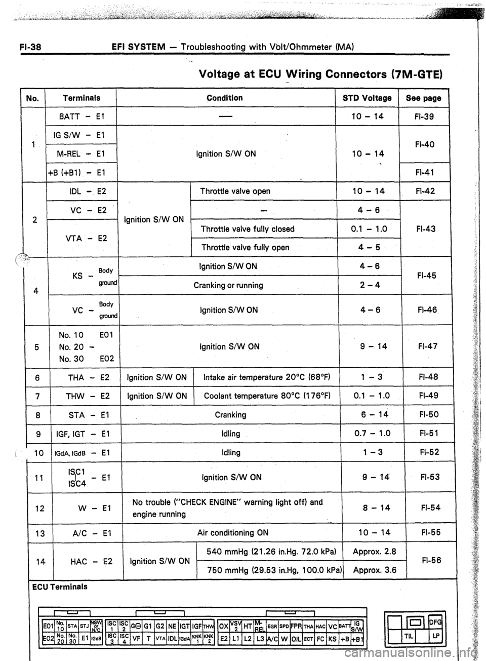
Voltage at ECU Wiring Connectors (7M-GTE)
No. Terminals
Condition STD Voltage Sea page
BATT - El 10 - 14
FI-39
IG S/W - El
1
FI-40
M-REL - El Ignition S/W ON 10 - 14
+B (+Bl) - El
FI-41
*
IDL - E2 Throttle valve open 10 - 14 FI-42
VC - E2 4-6.
2 . Ignition S/W ON
Throttle valve fully closed 0.1 - 1.0 FI-43
VTA - E2
Throttle valve fully open 4-5
i
KS - Body Ignition S/W ON 4-6
FI-45
gnMid
4 Cranking or running 2-4
vc - Body
Ignition S/W ON 4-6
groulld Fl-46.
No. 10 EOl
5 No. 20 - Ignition S;W CN 9 - 14 Fl-47
No. 30 E02
6 THA - E2 Ignition S/W ON Intake air temperature 20°C (68°F) 1 -3 FI-48
7 THW - E2 Ignition S/W ON Coolant temperature 80°C (176°F) 0.1 - 1 .O FI-49
8 STA - El Cranking 6-14 FI-50
9 IGF, IGT - El Idling 0.7 - 1.0 FI-5 1
10 IGdA, IGdB - El Idling 1-3 FI-52
11 I Cl
7 9 - 14 FI-53
ISC4 - El Ignition S/W ON
12 W - El No trouble (“CHECK ENGINE” warning light off) and
engine running 8 - 14 FI-54
13 A/C - El
14 HAC - E2 Air conditioning ON 10 - 14
FI-55
540 mmHg (21.26 in.Hg. 72.0 kPa) Approx. 2.8
Ignition S/W ON FI-56
750 mmHg (29.53 in.Hg, 100.0 kPa) Approx. 3.6
ECU Terminals
I U 1 I -
I
1
‘yc ‘;c GQ Gl G2 NE IGT IGF ~Hln, OX “;’ HT r;,
EGR SPD FPR THA HAC VC ‘JAn& 0 DF
‘;’ ‘sd: VF T VTA IDL
WA ““1” K;K E2 Ll L2 L3 NC W OIL ECT FC KS +B +Bl m
TIL LP
Page 81 of 346
EFI SYSTEM - Troubleshooting with Volt/Ohmmeter (MA)
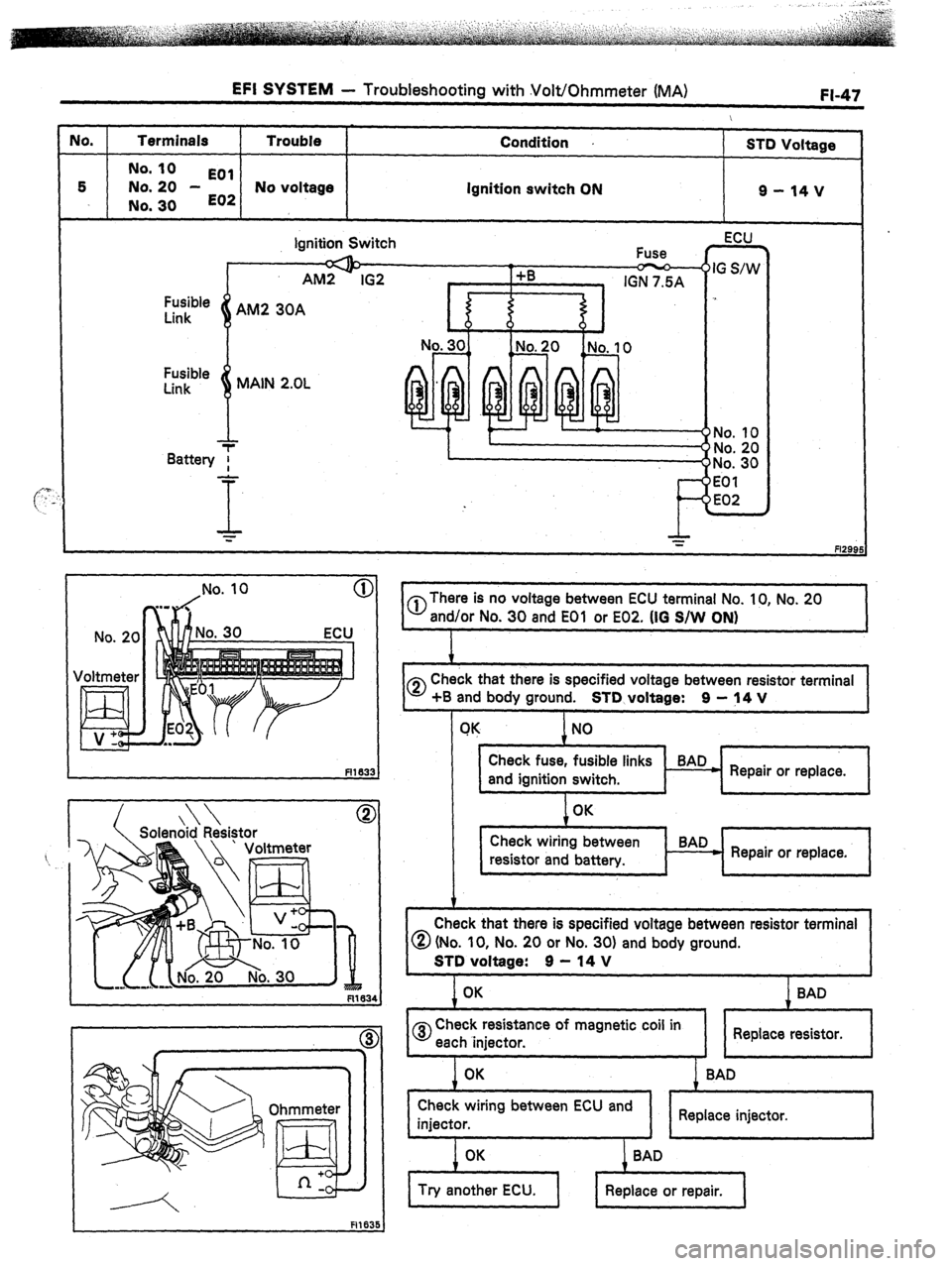
JO. Terminals Trouble Condition
S-m Voltage
No. IO
EOl
5 No. 20 -
E02 No voltage Ignition switch ON 9-14v
No. 30
Fusible
Link
8 MAIN 2.OL
-T
T
Battery f
-
I
= -“No. 10
I c
FIZE
Ignition Switch ECU
No. 2C
Voltmeter
A Solenoid Resistor
nr R?r
0 There is no voltage between ECU terminal No. 10, No. 20
and/or No. 30 and EOl or E02. (IO S/W ON)
1.
0 Check that there is specified voltage between resistor terminal
+B and body ground. STD voltaae: 9 - 14 V
1 NO 1
.
Check fuse, fusible links BAD
and ignition switch. - Repair or replace.
I i
1 OK I
I I ,
1
Check wiring between
resistor and battery. BAD
- Repair or replace.
Check that there is specified voltage between resistor terminal
@ (No. IO, No. 20 or No. 30) and body ground.
j ‘,.“.““!
I 0
Check resistance of magnetic coil in
each lniector. I 1 Replace resistor.
I
I . J I I
Page 92 of 346
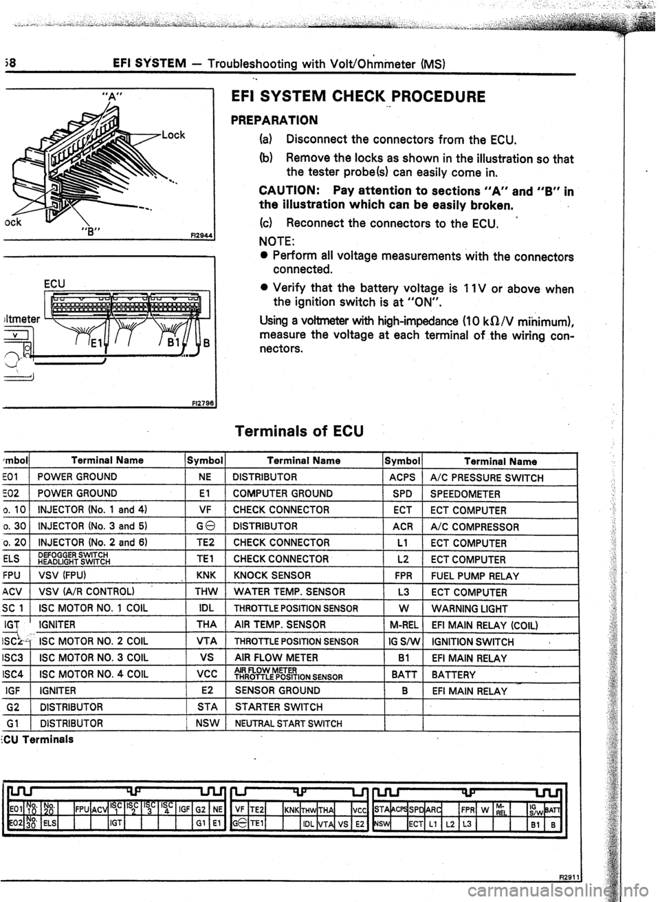
jS EFI SYSTEM - Troubleshooting with Volt/Ohmmeter (MS)
-.
0
“B”
Fl294.
ECU
EFI SYSTEM CHECK PROCEDURE
._
PREPARATION
(a) Disconnect the connectors from the ECU.
(b) Remove the locks as shown in the illustration so that
the tester probe(s) can easily come in.
CAUTION: Pay attention to sections “A” and “B” in
the illustration which can be easily broken,
(c) Reconnect the connectors to the ECU.
’
NOTE:
0 Perform ail voltage measurements with the connectors
connected.
0 Verify that the battery voltage is 1 IV or above when
the ignition switch is at “ON”.
Using a voltmeter with high-impedance (10 kQ/V mihimum),
measure the voltage at each terminal of the wiring con-
nectors.
Terminals of ECU
rmbol Terminal Name Symbol Terminal Name
Symbol Terminal Name
EOI POWER GROUND NE DISTRIBUTOR ACPS A/C PRESSURE SWITCH
co2 POWER GROUND El COMPUTER GROUND SPD SPEEDOMETER
o. 10 INJECTOR (No. 1 and 4) VF CHECK CONNECTOR ECT ECT COMPUTER
o. 30 INJECTOR (No. 3 and 5)
GO DISTRIBUTOR ACR A/C COMPRESSOR
o. 20 INJECTOR (No. 2 and 6) TE2 CHECK CONNECTOR Ll
ECT COMPUTER
ELS DEFOGGER SWITCH
HEADLIGHT SWITCH TEl CHECK CONNECTOR L2
ECT COMPUTER
FPU VSV (FPU) KNK KNOCK SENSOR FPR FUEL PUMP RELAY
ACV VSV (A/R CONTROL) THW WATER TEMP. SENSOR L3 ECT COMPUTER
SC 1 ISC MOTOR NO. 1 COIL IDL
THROTTLE POSITION SENSOR W
WARNING LIGHT
IGT IGNITER THA AIR TEMP. SENSQR
M-REL EFI MAIN RELAY (COIL)
SC- ISC MOTOR NO. 2 COIL VTA THROlTLE POSITION SENSOR IG SiW IGNITION SWITCH 3
ISC3 ISC MOTOR NO. 3 COIL vs AIR FLOW METER Bl EFI MAIN RELAY
ISC4 ISC MOTOR NO. 4 COIL vcc AIR FLOW METER
THROTTLE POSITION SENSOR BATT BATTERY
IGF IGNITER E2
SENSOR GROUND B
EFI MAIN RELAY
G2 1 DISTRIBUTOR 1 STA 1 STARTER SWITCH
Gl 1 DISTRIBUTOR 1 NSW 1 NEUTRALSTARTSWITCH
ZU Terminals
Page 120 of 346
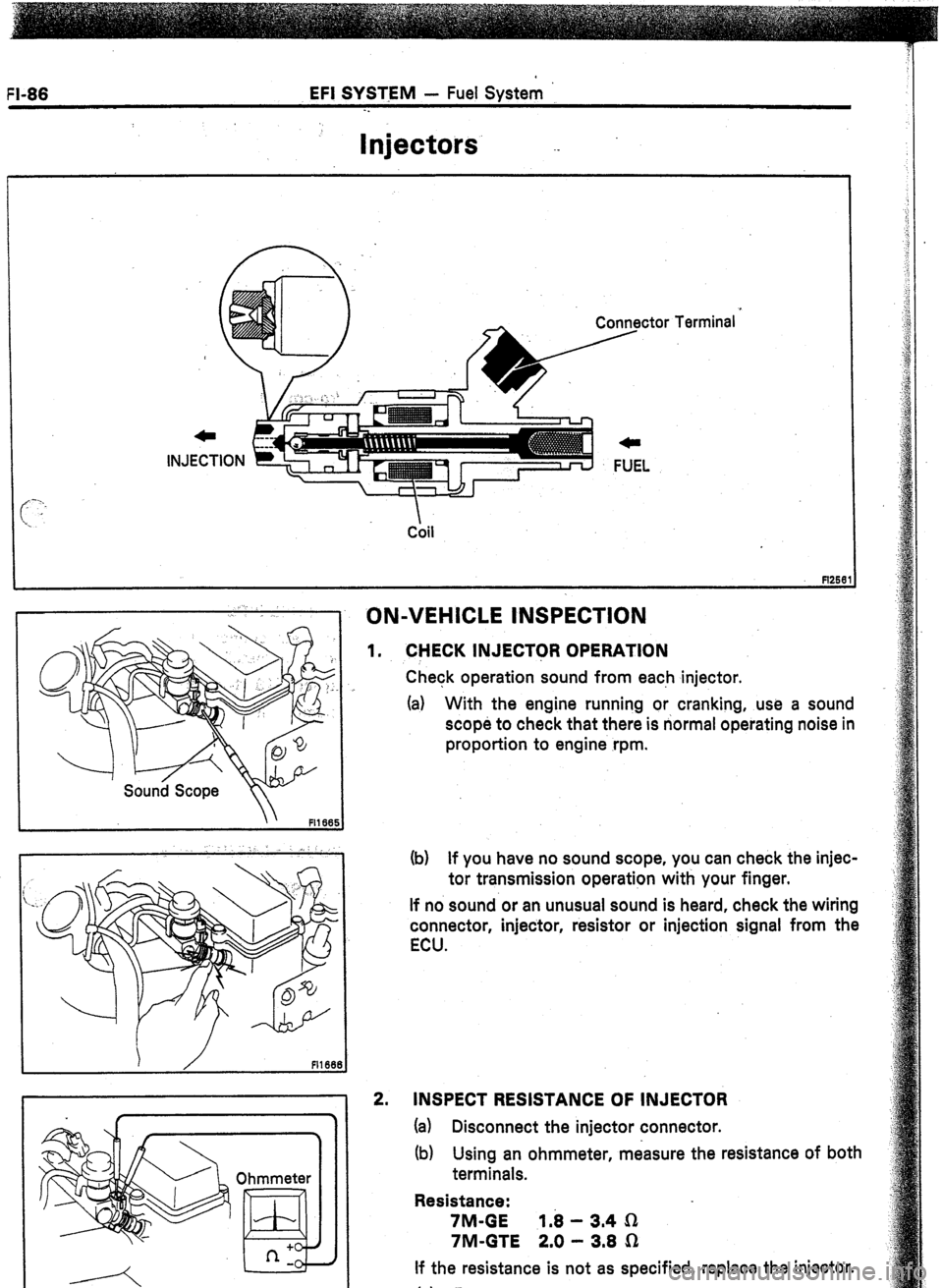
EFI SYSTEM - Fuel System
-.
Injectors --
Coil
1 ON-VEHICLE tNSPkTlON
1.
2. CHECK INJECToR OPERATION
Check operation sound from each injector.
(a) With the engine running or cranking, use a sound
scope to check that there is normal operating noise in
proportion to engine rpm.
(b) If you have no sound scope, you can check the injec-
tor transmission operation with your finger.
If no sound or an unusual sound is heard, check the wiring
connector, injector, resistor or injection signal from the
ECU.
INSPECT RESISTANCE OF INJECTOR
(a) Disconnect the injector connector.
(b) Using an ohmmeter, measure the resistance of both
terminals.
Resistance:
7M-GE 1.8 - 3.4 n
7M-GTE 2.0 - 3.8 Q
If the resistance is not as specified, replace the injector.
(c) Reconnect the injector connector.
Page 166 of 346
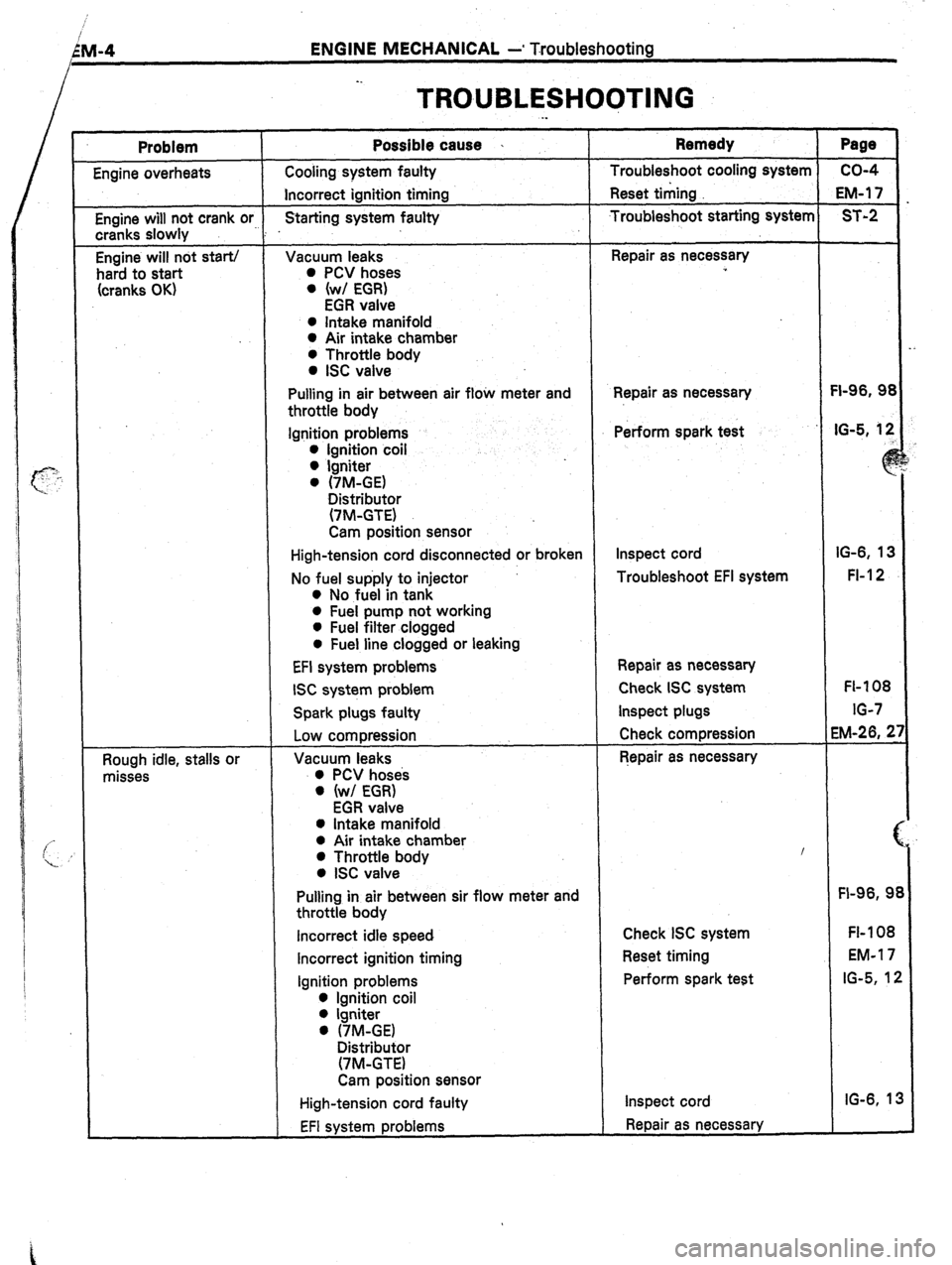
LM-4
I ENGINE MECHANICAL -* Troubleshooting
_.
TROUBLESHOOTING
Problem Possible cause I Remedy Page
Engine overheats Cooling system faulty Troubleshoot cooling system co-4
Incorrect ignition timing Reset timing EM-1 7
Engine will not crank or Starting system faulty Troubleshoot starting system ST-2
cranks slowly : .
Engine will not start/ Vacuum leaks Repair as necessary
hard to start 0 PCV hoses ”
(cranks OK) 0 (w/ EGR)
EGR valve
0 Intake manifold
0 Air intake chamber
0 Throttle body
0 ISC valve
Pulling in air between air flow meter and Repair as necessary FI-96, 93
throttle body
Ignition problems Perform spark test IG-5, 12
0 Ignition coil
0 Igniter
0 (7M-GE)
Distributor
(7M-GTE)
Cam position sensor
High-tension cord disconnected or broken Inspect cord IG-6, 13
No fuel supply to injector Troubleshoot EFI system FI-I 2
l No fuel in tank
0 Fuel pump not working
l Fuel filter clogged
0 Fuel line clogged or leaking
EFI system problems Repair as necessary
ISC system problem Check ISC system FL- 108
Spark plugs faulty Inspect plugs IG-7
Low compression Check compression EM-26, 2
Rough idle, stalls or Vacuum leaks Repair as necessary
misses 0 PCV hoses
0 (w/ EGR)
EGR valve
0 Intake manifold
0 Air intake chamber
0 Throttle body I
0 ISC valve
Pulling in air between sir flow meter and FI-96, 9
throttle body
Incorrect idle speed Check ISC system FI- 108
Incorrect ignition timing Reset timing EM-1 7
Ignition problems Perform spark test IG-5, 12
0 Ignition coil
0 Igniter
0 (-/M-GE)
Distributor
(-/M-GTE)
Cam position sensor
High-tension cord faulty Inspect cord IG-6, 13
EFI system problems Repair as necessary
Page 168 of 346
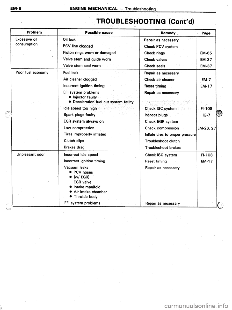
EM-6 ENGINE MECHANICAL - Troubleshooting
Problem
:- Excessive oil
consumption
Poor fuel economy
Unpleasant odor -.
TROUBLESHOOTING (Cont’d) ._
Possible cause
Oil leak
PCV line clogged
Piston rings worn or damaged
Valve stem and guide worn
Valve stem seal worn
Fuel leak
Air cleaner clogged
Incorrect ignition timing
EFI system problems
l Injector faulty
0 Deceleration fuel cut system faulty
Idle speed too high
Spark plugs faulty
EGR system always on
Low compression
Tires improperly inflated
Clutch slips
Brakes drag
Incorrect idle speed
Incorrect ignition timing
‘Vacuum leaks
0 PCV hoses
0 (w/ EGR)
EGR valve ’
0 Intake manifold
l Air intake chamber
l Throttle body
EFI system problems Remedy
Repair as necessary
Check PCV system
Check rings
Check valves
Check seals ~’
Repair as necessary
Check air cleaner
Reset timing
Repair as necessary
Check ISC system
Inspect plugs
Check EGR system
Check compression
Inflate tires to proper pressun
Troubleshoot clutch
Troubleshoot brakes
Check ISC system
Reset timing
Repair as necessary
Repair as necessary Page
EM-65
EM-37
EM-37
EM-7
EM-l 7
FI-108
IG-7
M-26, 2’
FI-108
EM-l 7