Page 9 of 346
CH-2 CHARGING SY&EM - Precautions, Troubleshooting
._
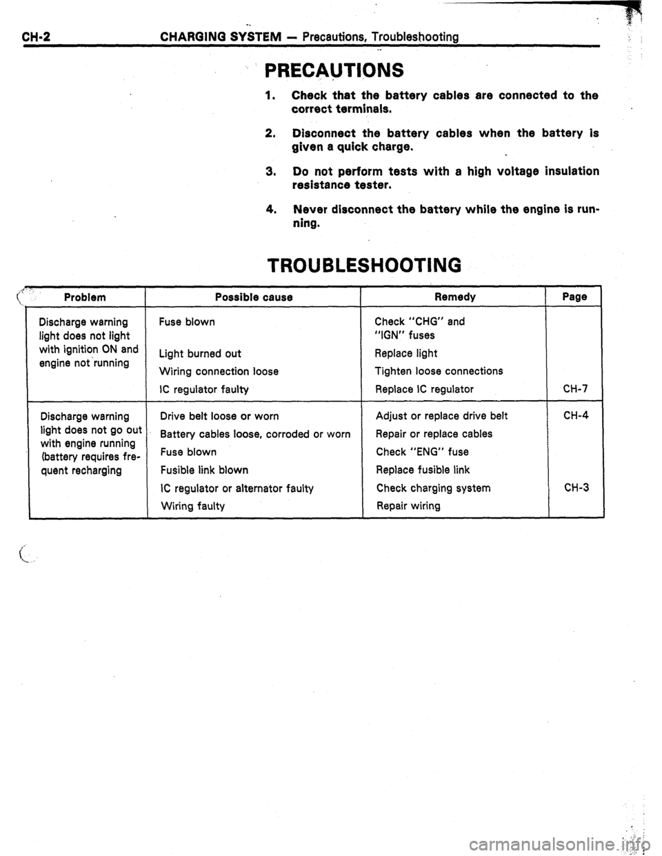
: PRECAUTIONS
1. Check that the battery cables are connected to the
correct terminals.
2. Disconnect the battery cables when the battery is
given a quick charge.
3. Do not perform tests with a high voltage insulation
resistance tester.
4. Never disconnect the battery while the engine is run-
ning.
Discharge warning
light does not light
with ignition ON and
engine not ‘running
Problem
Discharge warning
light does not go out
with engine running
(battery requires fre-
quent recharging
Possible cause
Fuse blown
Light burned out
Wiring connection loose
IC regulator faulty
TROUBLESHOOTING
Remedy
Check “CHG” and
“IGN” fuses
Replace light
Tighten loose connections
Replace IC regulator
Drive belt loose or worn
Battery cables loose, corroded or worn
Fuse blown
Fusible link blown
IC regulator or alternator faulty
Wiring faulty Adjust or replace drive belt
Repair or replace cables
Check “ENG” fuse
Replace fusible link
Check charging system
Repair wiring
Page
CH-7
CH-4
CH-3
Page 10 of 346
:usible
.ink
4LT
MA/
‘M-GE)
,258 Ignition Switch
Fuse
AM2 -0p IG2 (MA) 15~4
c (MS) 7.5A
Fusible
Link
AM2 30A
:usible
-ink
I (MA)
I/IAIN 2.OL (MS)
T Battery
P
/
CHG 7.5 A
I
i
8
I I .
i
m
Alternator
1 ON-VEHICLE INSPECTION
1.
tieI
fel
i 002
CHECK BATTERY SPECIFIC GRAVITY
(a) Check the specific gravity of each cell.
Standard specific gravity
When fully charged at 20°C (66°F):
1.25 - 1.27
If not within specifications, charge the battery.
(b) Check the electro!yte quantity of each cell.
If insufficient, refill with distilled (or purified) water.
’ 2. CHECK BATTERY TERMINALS, FUSIBLE LINKS AND
FUSES
(a) Check that the battery terminals are not loose or cor-
roded.
(b) Check the fusible links and fuses for continuity.
c
CHOZRRI
Page 24 of 346
co-4 CQOLING SYSTEM - Troubleshootmg
TROUBLESHOOTING
, Problem
Engine overheats Possible cause
Alternator drive belt loose or missing
Dirt, leaves or insects in radiator or
condenser
Hoses, water pump, water outlet
housing, radiator, heater, core plugs
or head gasket leakage
Thermostat faulty
Ignition timing
retarded
Fluid coupling faulty
Radiator hose plugged or rotted
Water pump faulty
Radiator plugged or cap faulty
Cylinder head or block cracked or
phwd Remedy
Adjust or replace belt
Clean radiator or condenser
Repair as necessary
Check thermostat
Set timing
Replace fluid coupling
Replace hose
Replace water pump
Check radiator
Repair as necessary Page
CH-4
CO-8
EM-l 7
CO-6
CO-6
co-9
Page 40 of 346
1-6 EFI SYSTEM - System Description
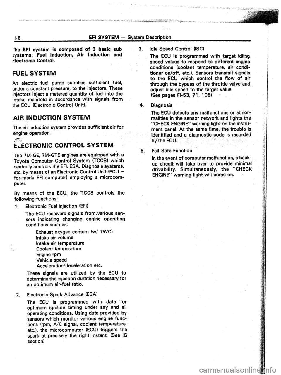
‘he .EFI system is composed of 3 basic sub
;ystems; Fuel Induction, Air Induction and
Ziectronic Control.
FUEL SYSTEM
An electric fuel pump supplies sufficient fuel,
under a constant pressure, to the injectors. These
injectors inject a metered quantity of fuel into the
intake manifold in accordance with signals from
the ECU (Electronic Control Unit).
AIR INDUCTION SYSTEM
The air induction system provides sufficient air for
engine operation.
[3: ‘I
i&TRONIC CONTROL SYSTEM
The 7M-GE, 7M-GTE engines are equipped wifh a
Toyota Computer Control System (TCCS) which
centrally controls the EFI, ESA, Diagnosis systems,
etc. by means of an Electronic Control Unit (ECU -
for-merly EFI computer) employing a microcom-
puter.
By means of the ECU, the TCCS controls the
following functions:
1. Electronic Fuel injection (EFI)
The ECU receivers signals from,various sen-
sors indicating changing engine operating
conditions such as:
Exhaust oxygen content (w/ TWC)
Intake air volume
i Intake air temperature
Coolant temperature
Engine rpm
Vehicle speed
Acceleration/deceleration etc.
These signals are utilized by the ECU to
determine the injection duration necessary for
an optimum air-fuel ratio.
2. Electronic Spark Advance (ESA)
The ECU is programmed with data for
optimum ignition timing under any and all
operating conditions. Using data provided by
sensors which monitor various engine func-
tions (rpm, A/C signal, coolant temperature,
etc.), the microcomputer (ECU) triggers the
spark at precisely the right instant. (See IG
section) 3. Idle Speed Control (IX)
The ECU is programmed with, target idling
speed values to respond to different engine
conditions (coolant temperature, air condi-
tioner on/off, etc.). Sensors transmit signals
to the ECU which control the flow of air
through the bypass of the throttle valve and
adjust idle speed to the target value.
(See pages FI-53, 7 1, 108) ’
4. Diagnosis
The ECU detects any malfunctions or abnor-
malities in the sensor network and tights the
“CHECK ENGINE” warning light on the instru-
ment panel. At the same time, the trouble is
identified and a diagnostic code is recorded
by the ECU.
5. Fail-Safe Function ’
In the event of computer malfunction, a back-
up circuit will take over to provide minimal
drivability. Simultaneously, the “CHECK
ENGINE” warning light will come on.
Page 41 of 346
EFI SYSTEM
- Precautions, Inspection Precautions
FI-7
PRECAUTIONS
._
1. Before working on the fuel system, disconnect the
negative terminal from the battery.
NOTE: Any diagnosis code retained by the computer will
be erased when the battery terminal is removed.
Therefore, if necessary, read the diagnosis before
removimg the battery terminal.
2. Do not smoke or work near an open flame when work-
ing on the fuel system.
3. Keep gasoline off rubber or leather parts.
INSPECTION PRECAUTl.ONS
MAINTENANCE PRECAUTIONS
1. INSURE CORRECT ENGINE TUNE-UP
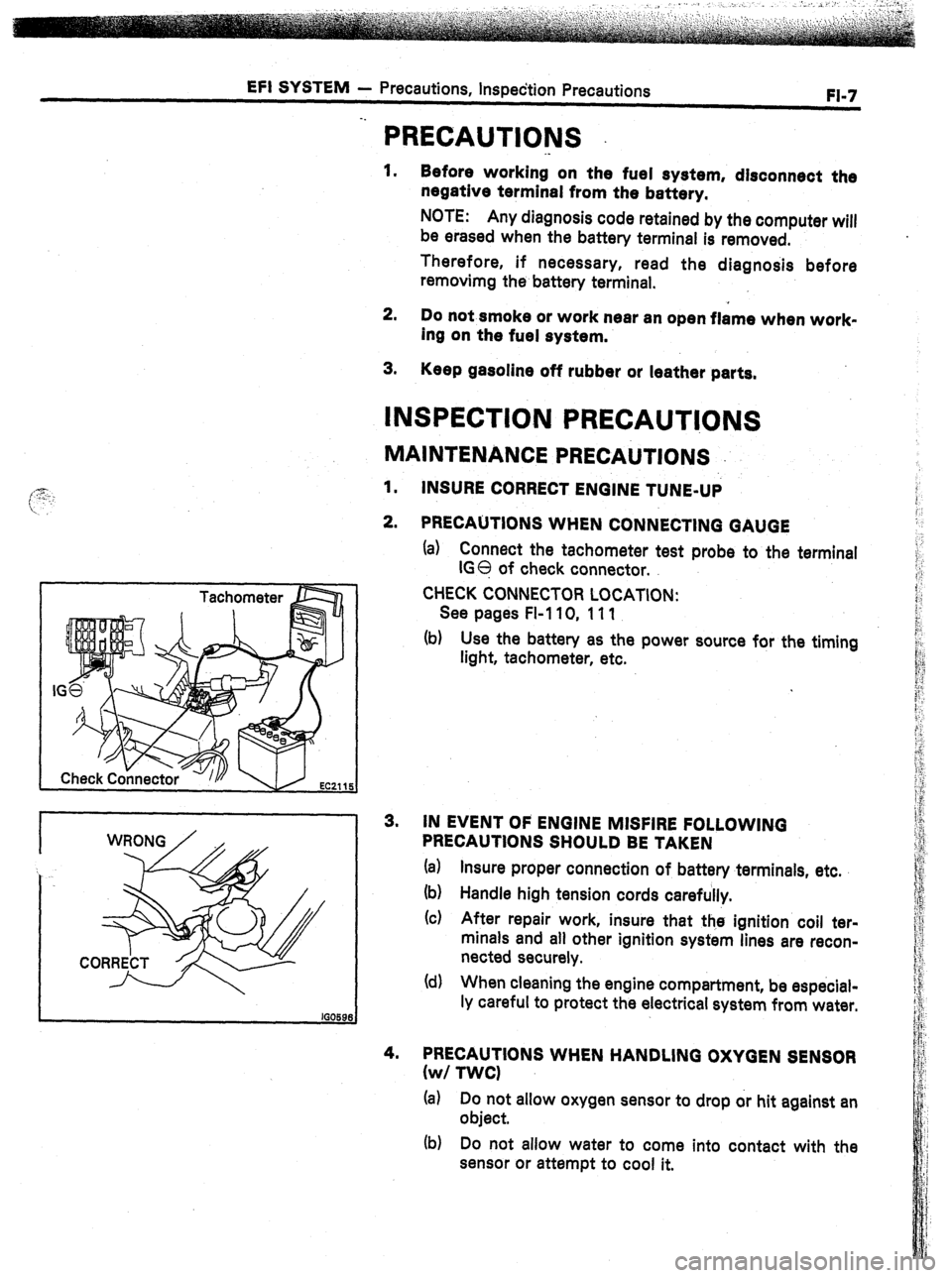
2. PRECAUTIONS WHEN CONNECTING GAUGE
(a) Connect the tachometer test probe to the terminal
IGO of check connector.
CHECK CONNECTOR LOCATION:
See pages FI-110, 111
(b) Use the battery as the power source for the timing
light, tachometer, etc.
3. IN EVENT OF ENGINE MISFIRE FOLLOWING
PRECAUTIONS SHOULD BE TAKEN
(a) Insure proper connection of battery terminals, etc.
(b) Handle high tension cords carefully.
(c) After repair work, insure that the ignition coil ter-
minals and all other ignition system lines are recon-
nected securely.
(d) When cleaning the engine compartment, be especial-
ly careful to protect the electrical system from water.
4. PRECAUTIONS WHEN HANDLING OXYGEN SENSOR
(w/ TWCI
(a) Do not allow oxygen sensor to drop or hit against an
object.
(b) Do not allow water to come into contact with the
sensor or attempt to cool it.
Page 43 of 346
EFI SYSTEM - inspection Precautions
FI-9
FM066
FlOO95 FlOO91
ELECTRONIC CONTROL SYSTEM
1.
2.
3. Before removing EFI wiring connectors, terminals, etc.,
first disconnect-the power-by either turning the ignition
switch OFF or disconnecting the battery terminals.
When installing a battery, be especially careful not to
incorrectly connect the positive and negative cables.
Do not permit parts to receive a severe impact during
removal or installation. Handle all EEI parts carefully.
especially the ECU.
4. Do not be careless during troubleshooting as there are
numerous transistor circuits and even slight terminal con-
tact can cause further troubles.
5.
6. Do not open the ECU cover.
When inspecting during rainy weather, take care to pre-
vent entry of water. Also, when washing the engine com-
.partment, prevent water from getting on the EFI parts and
wiring connectors.
7. Parts should be replaced as an assembly.
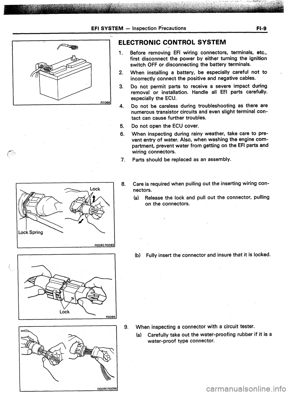
8. Care is required when pulling out the inserting wiring con-
nectors.
(a) Release the lock and pull out the connector, pulling
on the connectors. .
(b) Fully insert the connector and insure that it is locked.
9. When inspecting a connector with a circuit tester.
(a) Carefully take out the water-proofing rubber if it is a
water-proof type connector.
Page 45 of 346
EFI SYSTEM
- inspection Precautions
FI-11
I CORRECT i
Gro
Q * Delivery
Ring pipe
*
Black Ring
Delivew
Pipe -
O-Ring
-Grommet
3.
4.
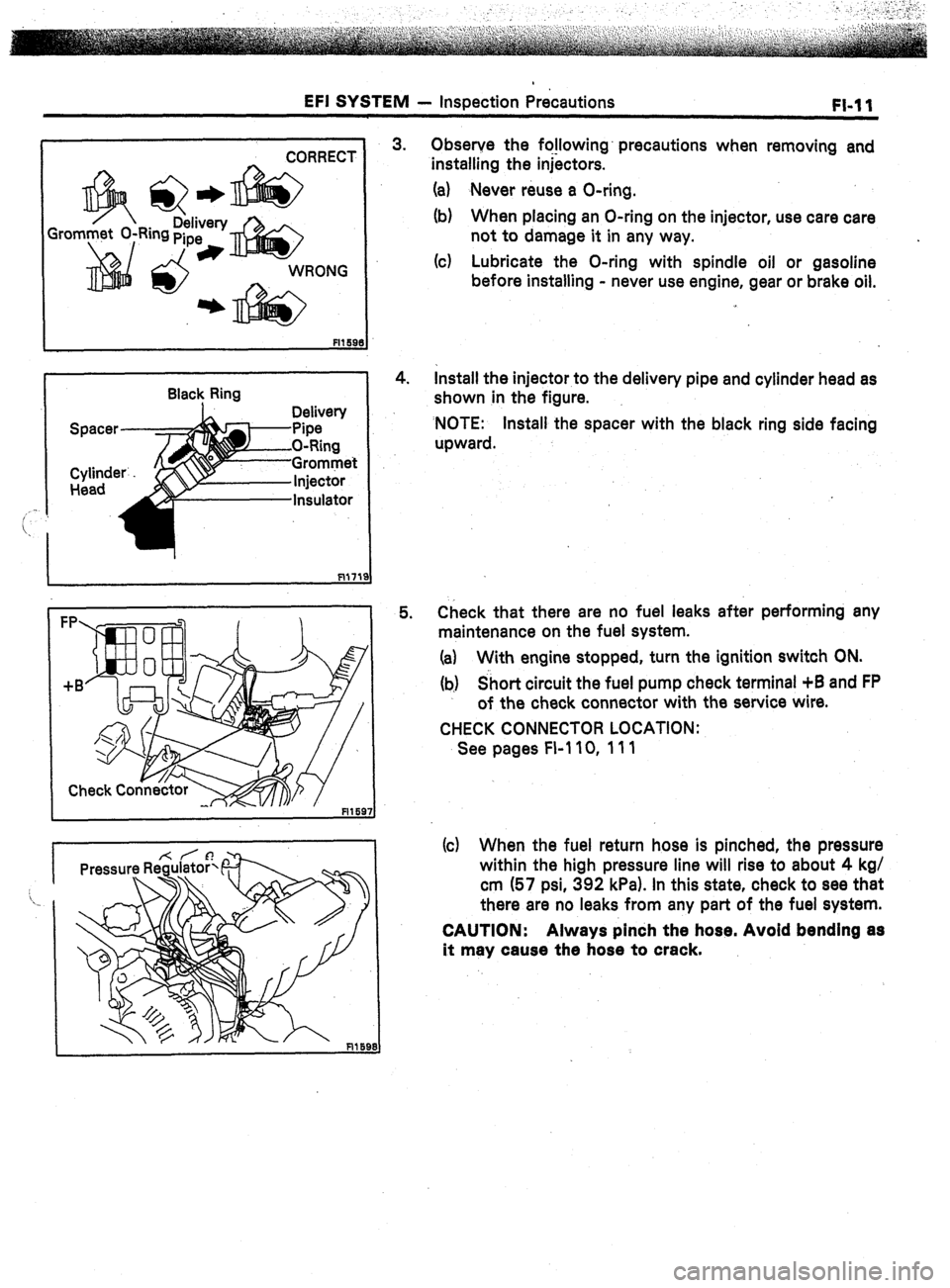
5. Observe the fo!lowing’ precautions when removing and
installing the injectors.
(a) Never reuse a O-ring.
(b) When placing an O-ring on the injector, use care care
not to damage it in any way.
(c) Lubricate the O-ring with spindle oil or gasoline
before installing - never use engine, gear or brake oil.
Install the injector to the delivery pipe and cylinder head as
shown in the figure.
‘NOTE: Install the spacer with the black ring side facing
upward.
Check that there are no fuel leaks after performing any
maintenance on the fuel system.
(a) With engine stopped, turn the ignition switch ON.
(b) Short circuit the fuel pump check terminal +B and FP
of the check connector with the service wire.
CHECK CONNECTOR LOCATION:
See pages FI-110, 111
(c) When the fuel return hose is pinched, the pressure
within the high pressure line will rise to about 4 kg/
cm (57 psi, 392 kPa). In this state, check to see that
there are no leaks from any part of the fuel system.
CAUTION: Always pinch the hose. Avoid bending as
it may cause the hose to crack.
Page 46 of 346
1-12 EFI SYSTEM - Troubleshooting’
FlO48
TROUBLESH~~TI~~G
. .
TROUBLESHOOTING HlhJTS
1. Engine troubles are usually not caused by the EFI system.
When troubleshooting, always first check the condition of
the other systems.
(a) Electronic source
0 Battery
0 Fusible links
0 Fuses
(b) Body ground
(cl Fuel supply
0 Fuel leakage
0 Fuel filter
0 Fuel pump
(d) Ignition system
0 Spark plug
0 High-tension cord
l Distributor (7M-GE) or cam position sensor (7M-
GTE)
0 Igniter and ignition coil
(e) Air induction system
0 Vacuum leaks
(f) Emission control system
0 PCV system
0 EGR system (w/ EGR)
(g) Others
l Ignition timing (ESA system)
0 Idle speed (ISC system)
-r
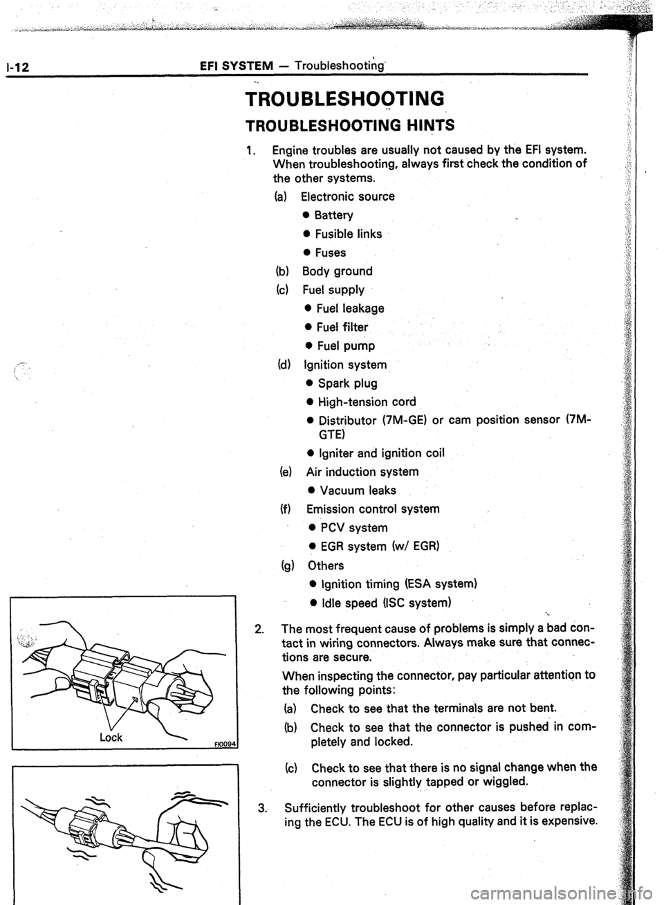
2. The most frequent cause of problems is simply a bad don-
tact in wiring connectors. Always make sure that connec-
tions are secure.
When inspecting the connector, pay particular attention to
the following points:
(a) Check to see that the terminals are not bent.
(b) Check to see that the connector is pushed in com-
pletely and locked.
(c) Check to see that there is no signal change when the
connector is slightly tapped or wiggled.
3. Sufficiently troubleshoot for other causes before replac-
ing the ECU. The ECU is of high quality and it is expensive.