1987 SUZUKI GRAND VITARA service
[x] Cancel search: servicePage 32 of 962
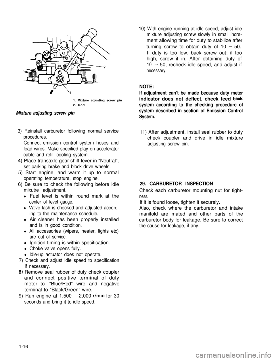
1. Mixture adjusting screw pin
2. Rod
Mixture adjusting screw pin
10) With engine running at idle speed, adjust idle
mixture adjusting screw slowly in small incre-
ment allowing time for duty to stabilize after
turning screw to obtain duty of 10 - 50.
If duty is too low, back screw out; if too
high, screw it in. After obtaining duty of
10- 50, recheck idle speed, and adjust if
necessary.
NOTE:
If adjustment can’t be made because duty meter
indicator does not deflect, check feed baCk
system according to the checking procedure of
system described in section of Emission Control
System.
3) Reinstall carburetor following normal service
procedures.
Connect emission control system hoses and
lead wires. Make specified play on accelerator
cable and refill cooling system.
11) After adjustment, install seal rubber to duty
check coupler and drive in idle mixture
adjusting screw pin.
4) Place transaxle gear shift lever in “Neutral”,
set parking brake and block drive wheels.
5) Start engine, and warm it up to normal
operating temperature, stop engine.
6) Be sure to check the following before idle
mixutre adjustment.
l Fuel level is within round mark at the
center of level gauge.
l Valve lash is checked and adjusted accord-
ing to the maintenance schedule.
l Air cleaner has been properly installed
and is in good condition.
l All accessories (wipers, heater, lights etc)
are out of service.
29. CARBURETOR INSPECTION
Check each carburetor mounting nut for tight-
ness.
If it is found loose, tighten it securely.
Also, check where the carburetor and intake
manifold are mated and other parts of the
carburetor body for leakage. Be sure to correct
the cause for leakage, if any.
l Ignition timing is within specification.
l Choke valve opens fully.
l Idle-up actuator does not operate.
7) Check and adjust idle speed to specification
if necessary.
8) Remove seal rubber of duty check coupler
and connect positive terminal of duty
meter to“Blue/Red” wire and negative
terminal to “Black/Green” wire.
9) Run engine at 1,500 - 2,000 r/min for 30
seconds and bring it to idle speed.
1-16
Page 33 of 962
1-3. CHASSIS AND BODY
30. CLUTCH PEDAL INSPECTION
1) Check clutch pedal height. It should be the
same as brake pedal height.
2) Check clutch pedal free travel.
Clutch pedal free travel20 - 30 mm
(0.8 - 1.1 in.)
For the details of the above steps 1) and 2),
refer to MAINTENANCE SERVICE (p. 11-8) of
SECTION 11.
31. BRAKE DISCS, PADS, BRAKE DRUMS
AND SHOES INSPECTION
Brake Discs and Pads
I) Remove wheel and caliper but don’t discon-
nect brake hose from caliper.
2) Check front disc brake pads and discs for
excessivewear,damageand deflection.
Replace parts as necessary. For the details,
refer to p. 19-I 6 and 19-I 7 of SECT ION 19.
Be sure to torque caliper guide pins to specifi-
cation for reinstallation.
Brake Drums and Shoes
I) Remove wheel and brake drum.
2) Check rear brake drums and brake linings for
excessive wear and damage, while wheels and
drums are removed. Also check wheel cylin-
ders for leaks, at the same time. Replace
these parts as necessary.
For the details, refer to p. 19-21 and p. 19-
22 of SECTION 19.
32. BRAKE HOSES AND PIPES INSPECTION
Check brake hoses and pipes for proper hook-
up, leaks, cracks, chafing and other damage.
Replace any of these parts as necessary.
CAUTION:
After replacing any brake pipe or hose, be
sure to carry out air purge operation.
33. BRAKE FLUID INSPECTION AND
CHANGE
[INSPECTION]
1) Check around master cylinder and reservoir
for fluid leakage.
If found leaky, correct.
2) Check fluid level
If fluid level is lower than the minimum level
of reservoir, refilling is necessary. Fill reservoir
with specified brake fluids.
Brake fluid Speifi;t3ons
For the details, refer to MAINTENANCE
SERVICE (p. 19-42) of SECTION 19.
CAUTION:
Since the brake system of this car is factory-
filled with glycol-base brake fluid, do not
use or mix different type of fluid when
refilling the system; otherwise serious
damage will occur. Do not use old or used
brake fluid, or one taken from unsealed
container.
[CHANGE]
1) Change brake fluid. As fluid change procedure,
drain existing fluid from brake system com-
pletely, fill the system with above recom-
mended fluid and carry out air purge opera-
tion.
For description of air purge, refer to p. 19-46
and 19-47 of SECTION 19.
34. BRAKE PEDAL INSPECTION
Check brake pedal travel.
For -checking procedure, refer to PEDAL TRA-
VEL CHECK (p. 19-43) of SECTION 19.
35. BRAKE LEVER AND CABLE
INSPECTION
Parking Brake Lever
I) Check tooth tip of each notch for damage or
wear. If any damage or wear is found, replace
parking lever.
2) Check parking brake lever for proper opera-
tion and stroke, and adjust it if necessary.
For checking and adjusting procedures,
refer to PARKING BRAKE INSPECTION
AND ADJUSTMENT (p. 19-44) of SECTION
19.
1-17
Page 34 of 962
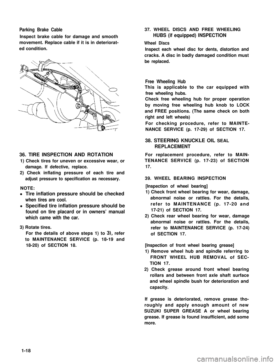
Parking Brake Cable
Inspect brake cable for damage and smooth
movement. Replace cable if it is in deteriorat-
ed condition.
36. TIRE INSPECTION AND ROTATION
1) Check tires for uneven or excessive wear, or
damage. If defective, replace.
2) Check inflating pressure of each tire and
adjust pressure to specification as necessary.
NOTE:
l Tire inflation pressure should be checked
when tires are cool.
l Specified tire inflation pressure should be
found on tire placard or in owners’ manual
which came with the car.
3) Rotate tires.
For the details of above steps 1) to 3), refer
to MAINTENANCE SERVICE (p. 18-19 and
18-20) of SECTION 18.
37. WHEEL DISCS AND FREE WHEELING
HUBS (if equipped) INSPECTION
Wheel Discs
Inspect each wheel disc for dents, distortion and
cracks. A disc in badly damaged condition must
be replaced.
Free Wheeling Hub
This is applicable to the car equipped with
free wheeling hubs.
Check free wheeling hub for proper operation
by moving free wheeling hub knob to LOCK
and FREE positions. (The same check on both
right and left wheels)
For checking procedure, refer to MAINTE-
NANCE SERVICE (p. 17-29) of SECTION 17.
38. STEERING KNUCKLE OIL SEAL
REPLACEMENT
For replacement procedure, refer to MAIN-
TENANCE SERVICE (p. 17-23) of SECTION
17.
39. WHEEL BEARING INSPECTION
[Inspection of wheel bearing]
1) Check front wheel bearing for wear, damage,
abnormal noise or rattles. For the details,
refer to MAINTENANCE (p. 17-20 and
17-21) of SECTION 17.
2) Check rear wheel bearing for wear, damage
abnormal noise or rattles. For the details,
refer to MAINTENANCE SERVICE (p. 17-24)
of SECTION 17.
[Inspection of front wheel bearing grease]
1) Remove wheel hub and spindle referring to
FRONT WHEEL HUB REMOVAL of SEC-
TION 17.
2) Check grease around front wheel bearing
rollars and between front axle shaft surface
and wheel spindle bush for deterioration and
capacity.
If grease is deteriorated, remove grease tho-
roughly and apply enough amount of new
SUZUKI SUPER GREASE A or wheel bearing
grease. If grease is found insufficient, add some
more.
1-18
Page 37 of 962
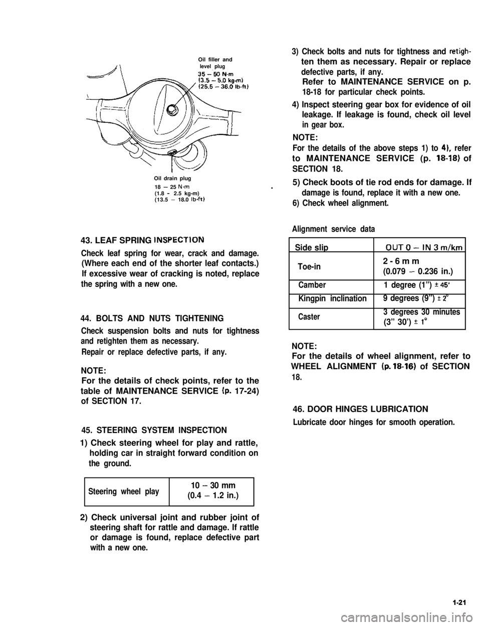
Oil filler andlevel plug
Oil drain plug
18 - 25 N.m(1.8 - 2.5 kg-m)(13.5 - 18.0 lb-ft)
43. LEAF SPRING lNSPECTlON
Check leaf spring for wear, crack and damage.
(Where each end of the shorter leaf contacts.)
If excessive wear of cracking is noted, replace
the spring with a new one.
44. BOLTS AND NUTS TIGHTENING
Check suspension bolts and nuts for tightness
and retighten them as necessary.
Repair or replace defective parts, if any.
NOTE:
For the details of check points, refer to the
table of MAINTENANCE SERVICE (p. 17-24)
of SECTION 17.
45. STEERING SYSTEM INSPECTION
1) Check steering wheel for play and rattle,
holding car in straight forward condition on
the ground.
Steering wheel play10 - 30 mm
(0.4 - 1.2 in.)
3) Check bolts and nuts for tightness and retigh-
ten them as necessary. Repair or replace
defective parts, if any.
Refer to MAINTENANCE SERVICE on p.
18-18 for particular check points.
4) Inspect steering gear box for evidence of oil
leakage. If leakage is found, check oil level
in gear box.
NOTE:
For the details of the above steps 1) to 41, refer
to MAINTENANCE SERVICE (p. 18-18) of
SECTION 18.
.5) Check boots of tie rod ends for damage. If
damage is found, replace it with a new one.
6) Check wheel alignment.
Alignment service data
Side slipOUTO-IN3m/km
Toe-in2-6mm
(0.079 - 0.236 in.)
Camber1 degree (1”) *45’
Kingpin inclination 9 degrees (9”) f 2’
Caster3 degrees 30 minutes
(3” 30’) f I0
NOTE:
For the details of wheel alignment, refer to
WHEEL ALIGNMENT (p. 18-16) of SECTION
18.
46. DOOR HINGES LUBRICATION
Lubricate door hinges for smooth operation.
2) Check universal joint and rubber joint of
steering shaft for rattle and damage. If rattle
or damage is found, replace defective part
with a new one.
1-21
Page 58 of 962
3-1.
3-2.
3-3.
3-5.
3-6.
3-7.
3-8.
3-9.
SECTION 3
ENGINE
CONTENTS
GENERAL DESCRIPTION.................................... 3-2
ENGINE SERVICES NOT REQUIRING ENGINE REMOVAL...... 3-5
ENGINE REMOVAL.......................................3-6
ENGINE DISASSEMBLY.................................. 3-9
INSPECTION OF ENGINE COMPONENTS....................3-17
ENGINE REASSEMBLY...................................3-35
ENGINE INSTALLATION.................................3-53
ENGINE MAINTENANCE SERVICE.........................3-53
RECOMMENDED TORQUE SPECIFICATIONS.................3-58
3-4.
3-1
3
Page 62 of 962
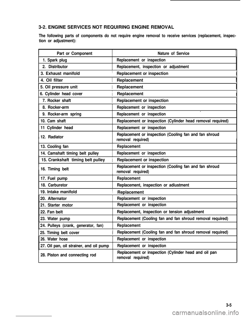
3-2. ENGINE SERVICES NOT REQUIRING ENGINE REMOVAL
The following parts of components do not require engine removal to receive services (replacement, inspec-
tion or adjustment):
Part or ComponentNature of Service1
1. Spark plug
2. Distributor
Replacement or inspection
Replacement, inspection or adjustment
1 3. Exhaust manifold1 Replacement or inspectionI
I 4. Oil filter1 ReplacementI
1 5. Oil pressure unit( Replacement
6. Cylinder head cover1 ReplacementI
I7. Rocker shaft1 Replacement or inspectionI
8. Rocker-arm
9. Rocker-arm spring
Replacement or inspection
Replacement or inspectionI
10. Cam shaft
11 Cylinder head
I12. Radiator
Replacement or inspection (Cylinder head removal required)
Replacement or inspection
Replacement or inspection (Cooling fan and fan shroud
removal required)I
13. Cooling fan
14. Camshaft timing belt pulley
Replacement
Replacement or inspection
I
15. Crankshaft timing belt pulley
16. Timing beltReplacement or inspection (Cooling fan and fan shroud
1 Replacement or inspection
removal required)
17. Fuel pump
18. Carburetor
Replacement
Replacement, inspection or adiustment
19. Intake manifold1 ReplacementI
20. Alternator
21. Starter motor
Replacement or inspection
22. Fan belt
23. Water pump
Replacement, inspection or tension adjustment
Replacement (Cooling fan and fan shroud removal required)
24.Pulleys (crank, generator, fan)Replacement
25. Timing belt cover)Replacement (Cooling fan and fan shroud removal required)
26. Water hose
27. Oil pan, oil strainer, and oil pump
Replacement or inspection
Replacement or inspection
28. Piston and connecting rodReplacement or inspection (Cylinder head and oil pan
removal required)
Replacement or inspection
3-5
Page 78 of 962
l Check end face of each valve stem for wear.
This face meets rocker arm intermittently
‘in operation, and might become concaved or
otherwise irregular. As necessary, smoothen
the end face with an oil stone and, if this
grinding removes the end stock by as much as
0.5 mm (0.0196 in.) (as measured from the
original face), replace the valve.
Limit on stock allowance0.5 mm
of valve stem end face(0.0196 in.)
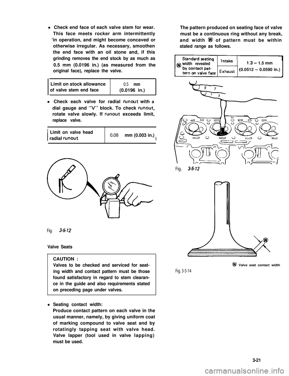
l Check each valve for radial runout with a
dial gauge and “V” block. To check runout,
rotate valve slowly. If runout exceeds limit,
replace valve.
I
Limit on valve head
radial runout0.08 mm (0.003 in.)I
Fig. 3-612
Valve Seats
CAUTION :
Valves to be checked and serviced for seat-
ing width and contact pattern must be those
found satisfactory in regard to stem clearan-
ce in the guide and also requirements stated
on preceding page under valves.
l Seating contact width:
Produce contact pattern on each valve in the
usual manner, namely, by giving uniform coat
of marking compound to valve seat and by
rotatingly tapping seat with valve head.
Valve lapper (tool used in valve lapping)
must be used.
The pattern produced on seating face of valve
must be a continuous ring without any break,
and width 6@ of pattern must be within
stated range as follows.
width revealed1.3- 1.5 mm
(0.0512 - 0.0590 in.)
Fig. 3-5-13
Fig. 3-5-14
@ Valve seat contact width
3-21
Page 87 of 962
Crankshaft Main (Journal) Bearings
General informations:
l Service main bearings are available in standard-
size and 0.25 mm (0.0098 in) undersize, and
each of them has 5 kinds of bearings differ-
ing in tolerance.
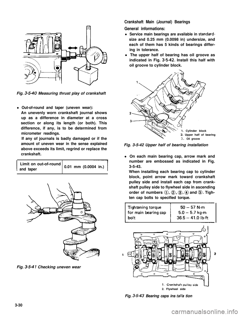
l The upper half of bearing has oil groove as
indicated in Fig. 3~5-42. Install this half with
oil groove to cylinder block.
Fig. 3-5-40 Measuring thrust play of crankshaft
l Out-of-round and taper (uneven wear):
An unevenly worn crankshaft journal shows
up as a difference in diameter at a cross
section or along its length (or both). This
difference, if any, is to be determined from
micrometer readings.
If any of journals is badly damaged or if the
amount of uneven wear in the sense explained
above exceeds its limit, regrind or replace the
crankshaft.
I
Limit on out-of-round
and taper0.01 mm (0.0004 in.)
Fig. 3-5-4 1 Checking uneven wear
1. Cylinder block2. Upper half of bearing
3. Oil groove
Fig. 3-5-42 Upper half of bearing installation
l On each main bearing cap, arrow mark and
number are embossed as indicated in Fig.
3-5-43.
When installing each bearing cap to cylinder
block, point arrow mark toward crankshaft
pulley side and install each cap from crank-
shaft pulley side to flywheel side in ascending
order of numbers @,a, 0, @ and 0. Tigh-
ten cap bolts to specified torque.
3
2. Flywheel side
Fig. 3-5-43 Bearing caps ins talla tion
3-30